
501705 - Server Intellinet - Free user manual and instructions
Find the device manual for free 501705 Intellinet in PDF.


| Product Type | Server |
| Brand | Intellinet |
| Model | 501705 |
| Form Factor | 1U Rackmount |
| Dimensions (W x D x H) | 48.3 cm x 55.0 cm x 4.4 cm |
| Weight | Approx. 12 kg |
| Power Supply | Dual redundant 550 W PSU |
| Input Voltage | 100 - 240 V AC, 50/60 Hz |
| Processor Support | Dual Intel Xeon Scalable |
| Memory Type | DDR4 ECC RDIMM, up to 512 GB |
| Storage Bays | 8 x 2.5" SATA/SAS hot-swap |
| RAID Support | Hardware RAID 0, 1, 5, 6, 10 |
| Network Interfaces | 2 x 10GbE SFP+, 2 x 1GbE RJ45 |
| Management | IPMI 2.0 with dedicated LAN |
| Operating Temperature | 0°C to 35°C (32°F to 95°F) |
| Maintenance | Clean dust filters monthly; check fan status regularly |
| Safety | Disconnect power before servicing; use anti-static wrist strap |
| Spare Parts | Hot-swap drives, power supply modules, fan trays |
| Repairability | Tool-less access to internal components; modular design |
| Warranty | 3 years limited parts and labor |
Frequently Asked Questions - 501705 Intellinet
User questions about 501705 Intellinet
0 question about this device. Answer the ones you know or ask your own.
Ask a new question about this device
Download the instructions for your Server in PDF format for free! Find your manual 501705 - Intellinet and take your electronic device back in hand. On this page are published all the documents necessary for the use of your device. 501705 by Intellinet.
USER MANUAL 501705 Intellinet
Thank you for purchasing our innovative all-in-one solution---SOHO Server 501705 appliance for your networking needs.
The SA integrates server services such as a Network Address Translator (NAT), Virtual Private Network (VPN), SPI firewall, and networked storage into one easy to manage device. The SOHO Server allows a group of trusted computers and networks to connect quickly and safely. With the SOHO Server, network managers and users can save time in establishing some of the most common services done on servers costing thousands of dollars.
Product Specifications
Connection Sharing
■ Flexible Address Space for NAT service
IP Alias
■ Multiple NAT
Virtual Private Network
■ PPTP Server / Client
Firewall
■ Prevent Denial of Service (DoS) Attacks
■ Packet/URL Filtering
■ Access Control, Virtual Server
System Management
■ Web-based Management for Configuring System
■ Firmware Update via HTTP
■ Reset To Factory Settings
■ Event Alert and Logs
■ System Information
Services
■ DHCP Client/Server
■ Proxy DNS
RIP
■ DDNS Client
■ FTP Server
Network
■ Programmable Static Route
■ Network Protocols Supported: PPPoE, TCP, UDP, ICMP, ARP
PPP Authentication
■ PAP, CHAP, MS CHAPv2
Real Time Clock
File Sharing
■ Supports CIFS, SMB, Appletalk(AFP), NFS
User Management
■ Local User Account Management
Power Management
■ Support Mechanical Off/Soft Off/Sleeping/Working System States
Other Features
■ Personal Web Server
■ USB Printer Server
■ USB Storage Sharing
■ Personal POP E-Mail Server
Benefits and Key Features
Virtual Private Network
With Virtual Private Networking, an enterprise can establish a dedicated tunnel among branch offices and/or mobile employees. All data is encrypted
and decrypted via the pre-defined dedicated tunnel. This prevents any hackers from stealing private information in the public network. With this functionality, any sub-network can be grouped as though they are in the same network.
Firewall
The SOHO Server provides a powerful firewall capable of preventing hackers from attacking the gateway or internal network. Many famous DoS attacks can be detected and prevented. Whenever an attack is detected, the system will alert the network manager that an attack has occurred. The network manager can then inspect the log information to find the IP address that sent the packets.
Easy Installation
In order to facilitate the use of the SOHO Server, the product comes with default settings that most network managers can install it without any modification. If the network manager needs to modify any of the settings, the SOHO Server provides an intuitive Web-based user interface.
Network Attached Storage
Network-attached storage (NAS) is the concept of shared storage on a network. NAS transfers data using industry standard file sharing protocols such as CIFS, AFP, NFS and FTP. Files can be shared simultaneously by clients regardless of the operating system they are using or the network server they are attached to. This solution provides convenient common storage resources.
Dynamic DNS
Dynamic DNS allows anyone wishing to reach your host by the name only. Dynamic DNS will map that name to your current IP address, which changes each time you dial your Internet service provider. With a URL that stays the same all the time regardless of IP address your options become almost as unlimited as a normal content provider like www.indiatimes.com or
www.yahoo.com.
USB Print Server
USB Print Server allows any computer in the network to share an USB printer. It complies with USB 2.0 specifications. And the users can print from any computer over a LAN.
Personal Web Server
The Personal Web Server enables users to host an information type website from their appliance. Create your website and place it on the appliance for the world to see. Use it in combination with our built-in DDNS client and anyone with a broadband connection can have their very own website.
Personal POP E-mail Server
The Personal POP E-mail Server provides users the ability to run a personal private e-mail server. Send e-mail you're your registered domain name or just create a DDNS account and have your personalized e-mail address.
FTP Server
FTP is the most secure, fastest, reliable method of transferring files. The FTP server allows you full control over who can login to the SOHO Server, which files the user can access or they could upload data.
Power Management
We divide the power management function into three parts. These are Power Down and Hard Disk Standby.
We'll describe each part in detail below.
- Power Down
We turn the power down in several ways:
■ Power Down by Web
Please select System Management -> Administrator Settings. In Power Down field, to select the enable radio button and then click
the apply button.
■ Power Down by press the power button
■ Prompt Power Down
Please press and hold the power button at least 4 seconds.
- Hard Disk Standby
If the hard disk is idle for a while, we would like the hard disk to enter standby mode to reduce the consumption of power. In the left menu, select NAS Management -> HD Initialization Wizard, in HD Power Management Setting, please select the time in the 'Turn Off hard disk' field (Figure 3.2a). If you select 'none', the hard disk will not enter the standby mode even if it is always idle. If you select '5 mins', the hard disk will enter standby mode once it is idle for more than five minutes.

Figure 3.2a
Physical Parts and Panel of the Smart Server
One WAN port: 10/100 Mbps
WAN port MDI/MDIX switch
Four LAN ports: 10/100 Mbps
Two USB 2.0 port
Reset Button
Power Button
Power Jack - DC 12V
LEDs: Link/Activity LEDs for Each Ethernet Port, Power LED,
HD (Hard Disk) LED, HB (Heart-Beat) & Packet Transmit/Receive LEDs
WAN Port
The WAN port is used to connect to an ADSL/Cable modem for linking to the Internet.
WAN MDI/MDIX Switch
The WAN MDI/MDIX switch is used to adjust the cable connection of the WAN port. If the port is connected to hub, you should move the switch to the "hub" side; if the port is connected to PC like machine, you should move the switch to the "PC" side. As for the four LAN ports, there is no need to add additional switches for each cable connection. This is because the LAN ports support auto MDI/MDIX.
LAN Ports
The LAN ports are used to connect to a PC, server, hub, switch or other network devices on the intranet.
Reset Button
If you forget your password and/or IP settings, you will not be able to access the SA. You can use the Reset Button to restore the factory settings. To
initiate a reset, you must hold the button for at least 5 seconds.
The primary default settings are listed in the following table.
| Configuration Item Default Settings | |
| Administrator Username | |
| Administrator Password Admin | |
| Internal IP address 172.16.1.1 |
Power Button
| Description of LEDsLED | Status Meaning | |
| Power | On | Power On |
| Off | Power Off | |
| Heart-Beat | Solid/Off System is not working | |
| Flashing | System is working | |
| WAN/LAN Link/Activity | On | Link up |
| Off | Link down | |
| Flash The interface is transmitting/receiving packets | ||
| 10/100 Mbps | On The network link is 100 Mbps WAN/LAN | |
| Off The network link is 10 Mbps | ||
| Throughput | No LED on | Current transfer rate is < 10KB/s |
| 1 LED on | Current transfer rate is >10KB/s | |
| 2 LEDs on | Current transfer rate is >50KB/s | |
| 3 LEDs on | Current transfer rate is >100KB/s | |
| 4 LEDs on | Current transfer rate is >500KB/s | |
Package Contents
- Smart Server
● Power Adapter and Power Cord - Ethernet cable
- User Manual CD
● Quick Installation Guide
Quick Installation
This chapter will give you brief instructions on how to install the product. In section 2.1, we will configure the hardware part of SA step by step. In section 2.2, we will check whether the IP address of your PC is assigned by DHCP. Once we complete the installation of the SA hardware and checked your PC settings, we will use the web-based management to configure the SA to suit your network environment. In section 2.3, and 2.4, we will review all the software settings. We will configure it to gain access to the Internet. If you need additional help or advanced setting details, please refer to the remaining chapters.
Hardware Installation
Please follow the steps below to install hardware:
-
Get the included Ethernet cable. Connect one end of it to the ADSL/Cable modem and the other end to the WAN port on the SA.
-
Get another Ethernet cable. Connect one end of it to the PC or hub and the other end to one of the LAN ports on the SA.
-
Turn the ADSL/Cable modem on. Note: Cable modem users MUST disconnect the cable modem from the wall outlet for at least 2 minutes before turning it on again.
If there are more PCs or hubs to be connected, please repeat step 2.
-
Connect the included power adapter to the power socket on the SA and then plug the power adapter into a wall outlet.
-
Turn on the SA. If the link LED of the WAN port is not ON, switch the WAN MDI/MDIX switch to the alternate setting.
The hardware installation is now complete.
Check Your PC First
Please check the following settings on your PC:
Do not assign an IP address to your PC.
-
Please select sequentially: In Start menu -> Settings -> Control panel -> Network connections -> Local Area Connection. Then a "Local Area Connection Status" window shows up. (Figure 2.2a)
-
Click the Properties button in Local Area Connection Status. Then the "Local Area Connection Properties" window shows up as Figure 2.2b.
-
Select Internet protocol (TCP/IP) item and then click the Properties button. The "Internet Protocol (TCP/IP) Properties" window shows up (Figure 2.2c).
-
Select the "Obtain an IP address automatically" radio button then click the OK button.

Figure 2.2a

Figure 2.2b
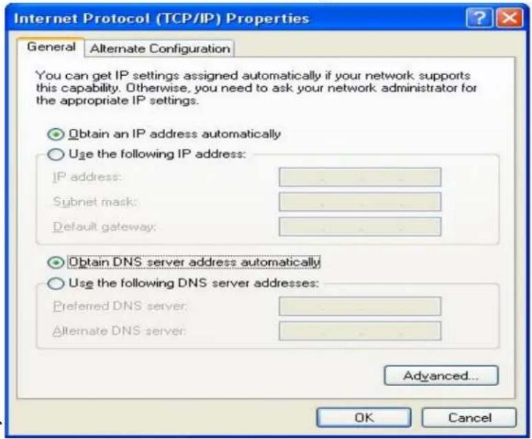
Figure 2.2c
Connect to the Web-Based Manager
Please follow the steps to connect to the web-based manager:
- Open a browser on the PC that is DIRECTLY connected to the SA.
Type "http://172.16.1.1" in address field. And then press Enter key.

- An authentication window shows up to prompt you to type the username and the password.
- Leave the username blank and type "admin" as a password. (Figure 2.3a.)
- Then press OK button. The default web page will appear like Figure 2.3b.

Figure 2.3a

Figure 2.3b
Web-Based Manager – Basic Settings
Start to configure your network environment by clicking the Basic Settings in left menu. The Basic Settings page is shown as Figure 2.4a.
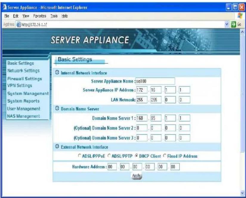
Figure 2.4a
The Basic Settings page contains Network Policy, Internal Network Interface, Domain Name Server, and External Network Interface. We describe these settings below in detail. You must click the apply button after you finish inputting the settings. You will see a rebooting window as Figure 2.4b. During the rebooting phase, do not turn off or unplug the SOHO Server.

Figure 2.4b
Internal Network Interface
The default settings are:
■ Host Name: "SA"
■ Private IP: "172.16.1.1"
■ Private IP Netmask: "255.255.0.0"
According to the default settings, we will assign the LAN to network "172.16.1.x" You can add more detailed configurations later in section 4.1 DHCP Server settings.
For the Network Address Translation (NAT) application, the private network address should be set in the following address range reserved by the Internet Assigned Numbers Authority (IANA).
| Class | Address | Range |
| A Class 10.0 | 0.0/10.255.255.255 | |
| B Class 172. | 16.0.0/172.31.255.255 | |
| C Class 192. | 168.0.0/192.168.255.255 | |
Domain Name Server
■ Most of the time this information is not needed, as your ISP will automatically provide the information.
■ Please ask the DNS IP address from your ISP if one is required.
External Network Interface
External network interface includes ADSL/PPPoE, DHCP Client and Fixed IP Address settings. Make sure that the system information webpage shows that your Link status is 'Link Up'. If not, please check your connection and/or switch the MDX switch located next to your WAN port. We have to choose one of the three ways to configure the external network interface. They are illustrated as follows:
Example 1: If you are connecting through a fixed IP address from the ISP. Example 2: If you are connecting through a dynamic IP address from ISP. Example 3: If you usually enter a username and password to access the Internet.
Example 1: Fixed IP Address Settings
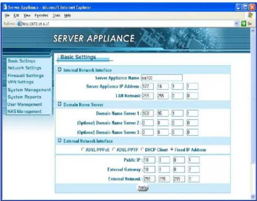
If you have a fixed IP address from your ISP to access the Internet, please follow the steps below:
- Select the Fixed IP Address radio button.
- Enter the Public IP address.
- Enter the External Gateway.
- Enter the External Netmask.
- Click the apply button.
Example 2: DHCP Client / Cable Modem

If you have a dynamic IP address from your ISP to access the Internet, please select the DHCP Client radio button. Once the external IP address is obtained via the DHCP protocol, there is no need to give an external IP address, external gateway address or netmask. The DHCP server will dynamically assign these fields. In general, you should choose this option if you are connecting the SOHO Server to a cable modem. Note: Cable modem users MUST disconnect the cable modem from the wall outlet for at least 2 minutes before turning it on again. Some cable modem connections need you to provide specific hardware address. For the case, you should fill your hardware address that you get from your ISP provider in Hardware Address field to override the original hardware address. However, it does not update the original hardware address stored in EEPROM. If you would not like to override the hardware address, you should set each field of the Hardware Address to zero "00".
Example 3: ADSL Connection
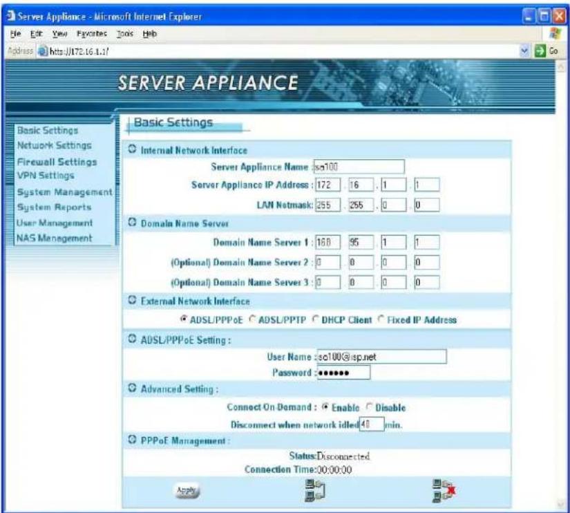
Most ADSL connections do not give you a fixed IP address. In this case, you must enter the user name and password provided by your ISP for authentication. Please follow the steps below.
- Please select the ADSL/PPPoE radio button.
- In ADSL/PPPoE Setting: Enter the User Name and Password.
- Click the apply button to save your settings.
After completing your configuration, each time the SA boots, it will try to connect with your ISP and the ISP will assign the SOHO Server an external IP address. Once successfully connected, the Status field should reflect this. If the Status is still the same, check to make sure that the username, password, cables, etc. are all correct.
Example 4: ADSL/PPTP Client Setting
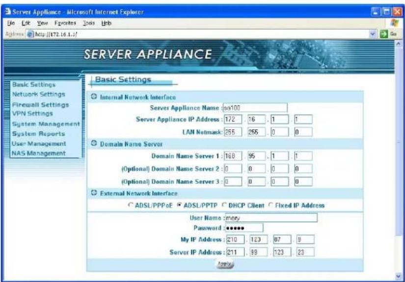
If your ISP provides a PPTP server, you could set up the PPTP client here.
Please follow the steps:
- Select ADSL/PPTP radio button.
- Enter the user name. (You get this from your ISP)
- Enter the password. (You get this from your ISP)
- Enter the IP address of your host in My IP Address.
- Enter the IP address of the server in Server IP Address.
In the following chapters, we will cover more details of configuring the SA.
Configuration Hierarchy
This chapter gives you an overview of all the configuration options available. The SOHO Server is a multifunction product. The section3.1 explains the corresponding settings for each function. And in section3.2, we describe the power management in detail.
There are eight main categories in configuration menu, Basic settings, Network settings, Firewall settings, VPN settings, System management, System reports, User management and NAS management. Each item has advanced configurations. See Figure 3.1.
Overview of Configuration Menu

flowchart
graph TD
    A["Logo Page"] --> B["Basic Settings"]
    A --> C["Network Settings"]
    A --> D["Firewall Settings"]
    A --> E["VPN Settings"]
    A --> F["System Management"]
    A --> G["System Reports"]
    A --> H["User Management"]
    A --> I["NAS Management"]

    B --> J["DHCP Server"]
    B --> K["IP Alias"]
    B --> L["Multiple NAT"]
    B --> M["Route Settings"]
    B --> N["DDNS"]

    C --> O["Virtual Server"]
    C --> P["URL Filter"]
    C --> Q["IP Filter"]
    C --> R["Denial of Service"]

    E --> S["PPTP Settings"]

    F --> T["Administrator Settings"]
    F --> U["Event Report Settings"]
    F --> V["Firmware Update"]
    F --> W["Time Settings"]
    F --> X["SNMP"]

    G --> Y["System Information"]
    G --> Z["System Log"]
    G --> AA["URL Log"]
    G --> AB["DHCP Lease Report"]

    H --> AC["Users"]
    H --> AD["Groups"]

    I --> AE["HD Initialization Wizard"]
    I --> AF["USB HD Info"]
    I --> AG["Advanced"]
    I --> AH["File Sharing"]
Figure 3.1
Network Settings
When you select Network Settings in the left menu of the web page, five configuration options appear: DHCP Server, IP Alias, Multiple NAT, Route Settings and DDNS. Please refer to the corresponding section for these configurations.

DHCP Server

In DHCP Server settings, we assign the rage of the virtual IP addresses for the four LAN ports of SA. All devices connect to the LAN ports of SA will be dynamically assigned the IP addresses within the range. If you wish to mix dynamic and static IP clients on your network:
Under DHCP server settings, the SA defaults to assigning IPs 172.16.1.2 through 172.16.1.250...So depending on how many fixed IP devices they have, they can assign their device to an IP of 172.16.1.251 (through 254) as these IPs will not be handed out by the SA. If they have more devices or want a different IP range, then all they need to do is modify the range that the SA hands out so it does not hand out an IP in that range. Typical offices set their DHCP server to assign IPs from 30 through 200. IPs 1 through 29 are usually assigned to servers and 201 and above are reserved for special uses.
You can either enable the DHCP server or disable it in this screen also.
■ To Enable the DHCP Server
If you do not have a DHCP server on your network,
- Select the Enable radio button.(already enabled by default).
- Enter a number in Lease time field.
- Enter the IP address range1 as "192.168.0.2" and "192.168.0.250" (default).
- Enter the IP address range2, otherwise enter "0" in each field.
- Enter the IP address range3, otherwise enter "0" in each field.
- Enter the IP address range4, otherwise enter "0" in each field.
- Click the apply button.
When DHCP server is enabled, it will allow DHCP clients to obtain their network configuration from the unit. In the figure above, the IP address range of 192.168.0.2 to 192.168.0.250 is dynamically assigned to individual DHCP clients. The DHCP client may be assigned an IP address like "192.168.0.10". The IP address "192.168.0.1" cannot be assigned as it is not in the range and is also assigned to SA under Basic Settings. If you assign another network (e.g. 192.168.1.x) to IP address ranges 2, 3, 4, please refer to section 4.2 for further IP Alias setting. When no other IP address ranges are assigned, a zero value should be filled in to indicate that no other IP addresses are available for assignment.
■ To Disable the DHCP Server
If you already have a DHCP server on your network,
- Select Disable radio button
- Click the apply button.
Or you do not have DHCP server on your network, but you would like to assign a static IP address to each device connected to the LAN port of SA.
- Select Disable radio button.
- Assign a static IP address to each device connected to the LAN port. For example, you have four PCs, PC1, PC2, PC3 and PC4 connected to the LAN port. You have to assign a UNIQUE static IP address i.e.
"192.168.0.34", "192.168.0.25", "192.168.0.18", "192.168.0.108" to PC1,
PC2, PC3 and PC4 respectively. Note: The static IP addresses
assigned are all in the same subnet with SA. In Basic Settings, we set "192.168.0.1" as private IP address of SA with a 255.255.255.0 subne
Therefore, the networked PCs need to belong to "192.168.0.x".
IP Alias
In Basic Settings, we've set the private IP address of SA as "192.168.0.1". We will assign the LAN ports of SA to the network of "192.168.0.x". In DHCP server settings, we've set the IP addresses of the LAN as "192.168.0.x". "192.168.0.x" includes "192.168.0.x", and therefore is considered to be in the same network. There is no problem if the network interface contains only one IP address range, but if you want to assign another IP addresses like "192.168.1.x" to the LAN, then there is an issue. "192.168.1.x" and "192.168.0.x" are not in the same network. We need IP Aliasing to resolve this issue. IP alias allows one network interface to contain more than one network. It allows the additional network "192.168.1.x" to be recognized by the SA.
Please follow the steps to add another network:
- Enter "192.168.1.1" in IP Alias 1.
- Enter "255.255.255.0" in Netmask of IP Alias 1.
- Click the apply button.
Note that the IP Alias 1, 192.168.1.1 is assigned to SA and the network is "192.168.1.x".
For additional IP addresses of the internal network interface to be accepted, enter the other IP address in IP Alias 2 and IP Alias 3. Enter "0" in each field if none.

Multiple NAT

If you get several fixed IP addresses from your ISP and the ISP restricts the bandwidth for each fixed IP address, you have to prevent the network
packets from always sending on the same IP address and the other IP address to sit idle. Multiple NAT solves this and allows you to increase the bandwidth. Multiple NAT allows you to dispatch your network packets evenly to these IP addresses provided by ISP.
- Enter the Internal IP range1, e.g. "172.16.1.1/24". It means the network is "172.16.1.x"
- Enter the External IP range1, the IP address range you get from your ISP.
- Enter the Internal IP range2, e.g. "192.168.1.1/24". It means the network is "192.168.1.x".
- Enter the External IP range2, the IP address range you get from your ISP.
- Or enter "0" in each field for non-setting multiple NAT.
- Click the apply button.
After you configure the Multiple NAT on the group of fixed IP addresses, it can increase the bandwidth. The Internal IP range you entered will be routed to the corresponding External IP range.
Route Settings

The Route Settings page gives you a way to set the static route. You have to set the static route if you would like to route your packets to the specific network and the router of the destination network does not support RIP
(Routing Information Protocol). If the router supports RIP, it will automatically exchange routing information with SA and it is not necessary to set a static route. Please refer the steps and figures to set a static route.
- Select Enable radio button in Routing Setup.
- Enter the network in Destination network column. (e.g. "192.168.6.0/24")
- Enter IP address of the gateway in Gateway column. (e.g. "172.16.1.249")
- Enter the number in Hop count column. The number means how many gateways you have to pass through.
- Click the apply button.
In the figures, the destination network is "192.168.6.x". And the packets will be route in or out of the destination network through the gateway "172.16.1.249".
DDNS

Your Internet Service Provider (ISP) provides you at least one IP address to use when connecting to the Internet. The address you as assigned may be static, meaning it never changes, or more than likely dynamic, meaning it's likely to change periodically. How often it changes depends on your ISP. A dynamic IP address complicates remote access since you may not know your current WAN IP address when you want to access your network over the
Internet. DDNS provides a simple, and in most cases free, solution.
The Internet uses DNS servers to lookup domain names and translates then into IP addresses. Domain names, such as www.yahoo.com, are just easy to remember aliases for IP addresses. A dynamic DNS service provides a means of updating your IP address so that you listing will be current when your IP address changes. There are several services on the Internet that are available for free. We will only cover one, www.dyndns.org. You will need to register with the service and setup a domain of your choice from the list they provide for you.
The DDNS service in our device works by uploading your new WAN IP address to the servers when it changes. You would only need to enter the account information in the DDNS setup page of your unit.
How to setup a DynDNS DDNS account:
- Access the DynDNS homepage (www.dyndns.org).
- If you have not registered, click 'Sign Up Now' to create a new account.
- Follow the instructions to create a free DDNS account. Requires only e-mail address.
- Log into your account by providing a username and password.
- Select 'Services' from the top menu.
- Select 'Dynamic DNS' from the choice of services.
- Select 'Add A Host' from the 'Your Hosts' section. Follow the instructions.
- Note your hostname so you can input it in the DDNS configuration for your device.
You can setup additional host names for additional devices.
Please follow the steps below to setup DDNS on your SA.
- Select Enable radio button in DDNS Client Service field.
-
Select the DDNS service provider.
-
Enter the User name. The user name you log in DDNS service.
- Enter the password. The password you log in DDNS service.
- Enter the Host name. The host name you register in DDNS service.
- Click the apply button.
Every time your public IP changes, the SA will tell the DDNS server what your new IP address is. Other users, through the magic of DDNS, will be sent to the right place.
Firewall Settings
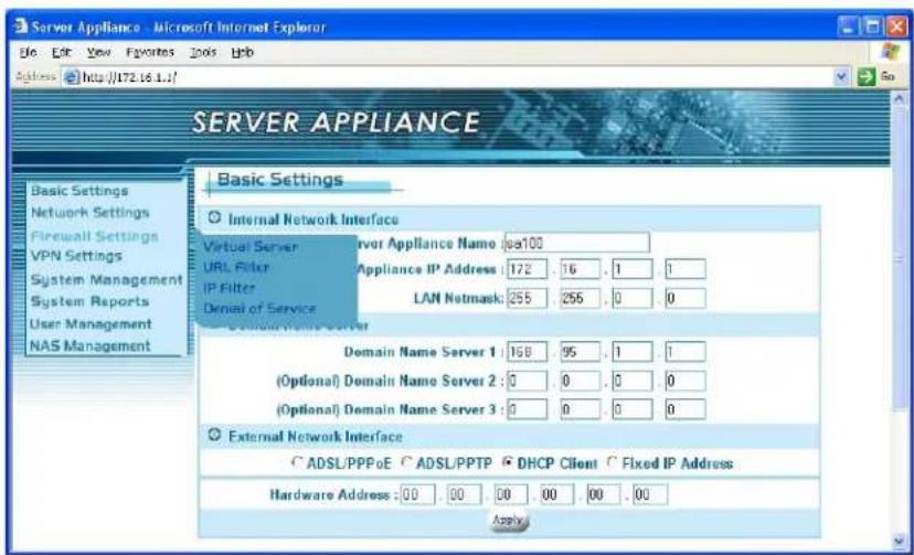
When you select the Firewall Settings item in left menu of the web page, four configuration items appear including: Virtual Server settings, URL Filter, IP Filter setup and Denial of Service. Please refer the corresponding section for each of these items.
Virtual Server Settings

The virtual server service is a way to simulate multiple servers on the intranet. You have several IP addresses within your LAN. These IPs are not visible to the users from the Internet. When servers are installed in the office that need to be seen from the Internet, we establish some forwarding rules to deal with the packet from the Internet users and direct the SA to forward the specific packets to the specific IP address. Users from the Internet could be allowed to access the specific server on your LAN. You can configure different IPs to act as different virtual servers. For example, the users accessing port 21 will be directed to “172.16.2.1”. “172.16.2.1” could be a FTP server. Users accessing port 80 will be directed to “172.16.2.2”, an HTTP server on the LAN. For users outside the LAN, they will feel like many services are running on a single host. Please follow the steps below.
- Select Enable radio button in Virtual Server.
- Enter the IP address, in LAN will be set as a virtual server.
- Select the Protocol.
- Enter the number in Ports, the users accessing the port will be directed to the virtual server in step 2.
- Please repeat the steps above to establish more virtual servers
or enter "0" in each field for none.
- Click the apply button.
URL Filter Setup

The URL Filter function is used to restrict internal hosts from accessing specific URL locations. You deny any access to the URL location specified in the Site1, Site2 ...Site10 fields.
Please follow the steps:
- Select Enable radio button in URL Filter.
- In Site 1, please enter the URL address.
- Please repeat the step 2 to build more URL addresses not allowed.
- Click the apply button.
If the Site1 is given as www.yahoo.com, any hosts in the intranet will not be allowed to connect to www.yahoo.com. If you do not restrict any access from intranet to Internet, please select the Disable radio button in the URL Filter.
IP Filter Setup

The IP filter function is similar to URL Filter. It provides further restrictions in access permission. URL Filtering only blocks port number 80 (HTTP). In IP filtering, you can assign a group of IP to be restricted. You can block four individual ports or a range of ports in the same time. So the specific group of intranet hosts cannot connect to these ports. Please follow the steps:
- Select Enable radio button in IP Filter.
-
Enter the IP address range in the format "x. x. x. x / x"(e.g. "192.168.1.0/24", you would like to restrict the IP group)
-
Select the Protocol.
-
Enter the port number in Blocked Ports No. There are four fields you can enter in any order or combination. You can enter one, two, etc.
-
Enter the range of port numbers (if any) in Blocked Port Range.
In the example, if any hosts that requests information from 192.168.1.1 to 192.168.1.254 in the intranet with port number 21, 23 or from 100 to 1024 with TCP protocol, will be blocked.
Denial of Service

It is highly recommended that the DoS Protection feature be enabled to prevent attacks on the network. However, if you allow someone to manage the router from outside or are running a web server, e-mail server, or FTP server, you should either disable Detect SYN Flood Attack or increase the TCP flow. Otherwise, the configuration web pages will not be sent smoothly.
VPN Settings
VPNs (Virtual Private Networking) provide secure communication between two separate networks without using a dedicated leased line. In order to achieve this functionality, a secure tunnel must be built between the two sites for secure communication over the Internet. The SA supports the most popular protocol - PPTP. PPTP (Point-to-Point Tunneling Protocol), described in RFC 2637 is a PPP-specific protocol proposed by Microsoft. The SA implements a PPTP server. The remote user can connect to the PPTP server and access a local host behind the PPTP server. When you select the VPN item in left menu of the web page, PPTP configuration options will appear. Please refer to the corresponding section for these configurations.
PPTP Settings
For most companies, the PPTP server creates a secure connection that a remote user can access a host within the company. The remote user has to run a PPTP client and connect to the PPTP server. The PPTP server has to validate the remote user as being in the User List in section 9.1. The server certifies the PPTP client with a username and password. After passing the certification, the server will assign a private IP address to the client. The remote user will be treated like a member of the LAN and can access the local hosts inside the company. Please refer to Appendix A for more details about configuring a PPTP VPN connection. To run the PPTP server on the company side, please follow the steps below:
- In PPTP Settings page: Select the Enable button in PPTP Server field. (Figure 6.1)
- Enter the private IP address of the server in Server IP Address field.
- Enter the Client IP Range. The server will assign the IP to each client within the range.
- Click the apply button.

Figure 6.1
System Management
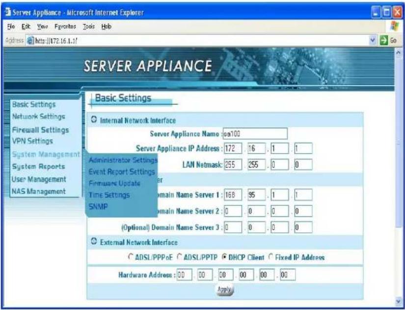
When you select the System Management item in the left menu, four configuration items appear including; Administrator Settings, Event Report Settings, Firmware Update, Time Settings and SNMP. Please refer the corresponding section for these configuration details.
Administrator Settings
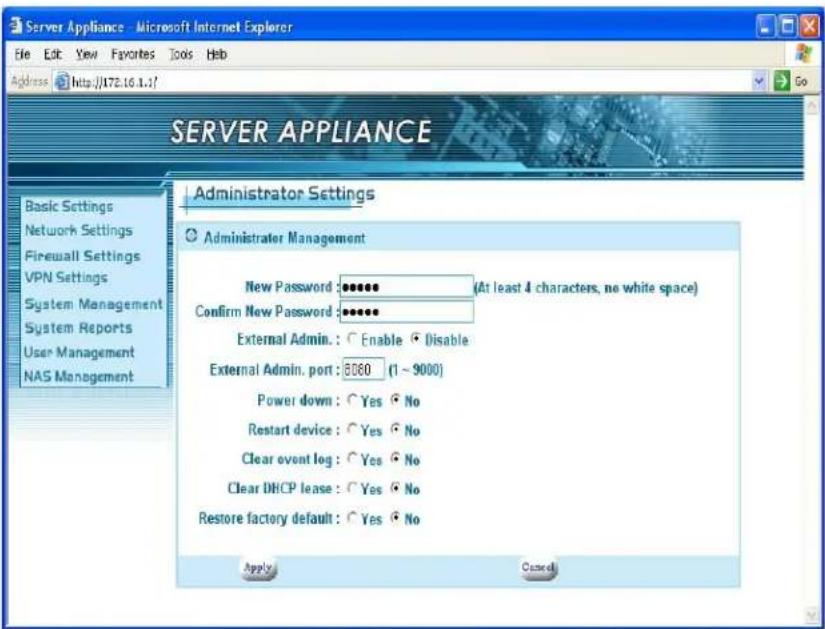
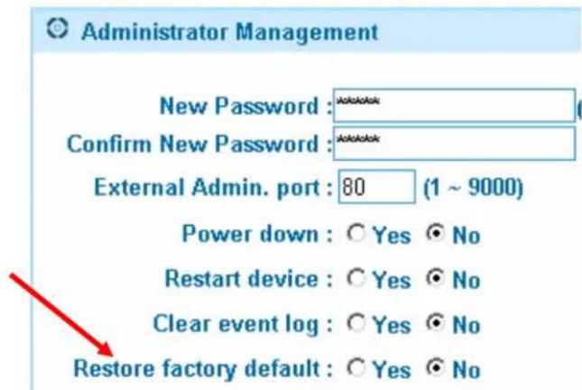
In Administrator settings you will find the basic administrator functions. The settings are easily modified and managed by the administrator. They are described as below:
- New Password: the administrator could change the administrator password here. Please enter the new password you would like to change to. Note that you must fill the new password in both Password change and Password confirmation fields. If both fields are not the same, the page will not be submitted.
- FTP Server: please select the enable radio button to establish the FTP server. Or select the disable radio button for none.
- Confirm New Password: please enter the new password again.
- External Admin.: This feature allows administrators to access the web based configuration menu from the Internet. The default setting for this feature is disabled for security reasons.
- External Admin. Port: defines a port for the remote
administrator to connect to.
-
Restart device: This function reboots the SOHO Server. Select the enable radio button to restart SA. The default setting of the function is disabled.
-
Clear event log: This function is used to clean the system history that is listed in Event Report (section 8.2). If you choose the "No" radio button, the event record never clears even when you reboot the system.
-
Clear DHCP lease: This function is used to clean the DHCP Lease record listed in section 8.4. Please choose the "Yes" radio button to clean DHCP lease report.
-
Restore Factory default: To recover the factory settings, please choose the "Yes" radio button and the factory defaults will be loaded.
-
Click the apply button.
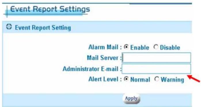
Event Report Settings
Send alerts to an e-mail account. The mail server should allow e-mails from the same network.
E-mail address to send the alerts to.
Firmware Update
Updates and functionality can be added via this function. Please check the web for the latest firmware if you are having any issues. In general, no update should be needed unless it is recommended by technical support. Note: Do not do a firmware update over a wireless connection or power the unit down during a firmware update. Any interruption during an update will damage your unit and require you to send it in for service.
Current firmware version

Select Browse and
locate the updated firmware. If the firmware file is not correct, it will not update the firmware in the unit. The version number will remain the same after the firmware update procedure.
The update percentage will update the status.

Click Restart when the upload is complete.
Though it is not generally necessary, you should Restore factory default to make sure that new features and settings are implemented. Note: You must re-initialize the hard drive if you do this.
Time Settings
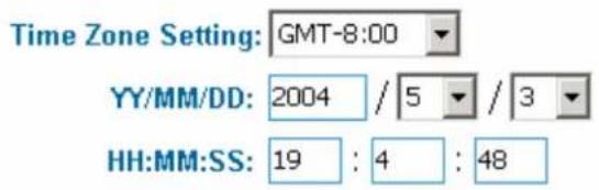
The NAS's built-in clock should be adjusted to the current local time. This will insure accurate time reporting in the logs and file records.
Select your GMT time zone and then enter the date and time. Click on Apply to make the changes.
Apply


You can find your GMT time zone by double clicking on the clock located on the bottom right corner of your desktop.
SNMP
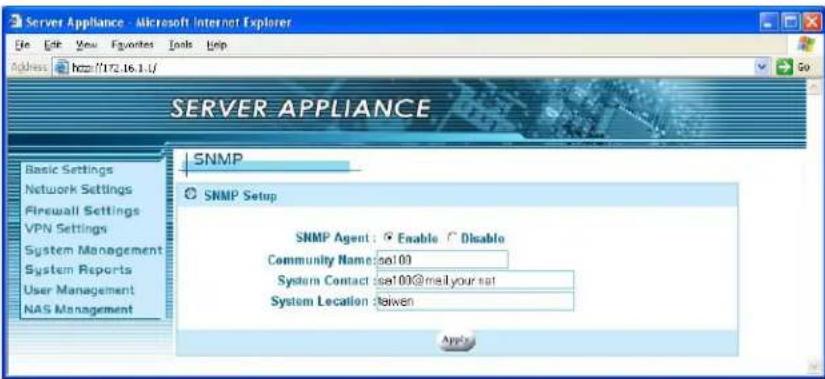
The SNMP agent allows users with SNMP client applications to conveniently inspect the network status of SA. Please
follow the steps below to setup the SNMP agent.
- Select the Enable radio button in the SNMP Agent field.
- Enter the Community Name. Note that the agent side and the client side must use the same community name.
- Enter the contact information in System Contact field. For example, the phone number or the email account of the administrator.
- Enter the location of the unit the System Location field.
- Click the apply button.
System Reports
When you select System Reports in the left menu of the web page, four configuration items appear including; System Information, System Log, URL Log, and DHCP Lease Report. Please refer to the corresponding section for these configuration items.

System Information

The System Information displays some useful information about the system. It shows the firmware version, the system up time and the internal and external network connections. On SA, We have one WAN port and four LAN ports. The WAN port belongs to the external network interface and the LAN port belongs to the internal network interface. They are described as below:
■ Firmware Version: 2.00
■ The system up time
■ IP Address: the IP address is shown as your current setting. In Chapter 2, section 2.4, the Basic setting, we already configure the external interface in one of the three ways, ADSL/PPPoE, DHCP client and Fixed IP address. In Chapter 4, section 4.1, DHCP
Server, we assigned the IP address range to the internal network interface.
■ Hardware Address: Ethernet hardware address
■ Netmask: corresponding to the network.
■ Max. Transfer Unit: maximum bytes of a packet.
■ Tx/Err Packets: e.g. 309/0, means you sent 309 packets and there are "0" packets with errors.
■ Rx/Err Packets: e.g. 3573/2, it means you received 3573 packets and there are 2 error packets.
■ Link Status: Shows the current transfer speed. e.g. 100Mbps, full duplex.
■ The refresh button: Click the refresh button to see if anything has been updated.
If your external connection is not set to a fixed IP address, you can check whether the SOHO Server has obtained an IP address after booting. If there is no external IP address, you should check your network connection or environment settings.
System Log
Use the information provided here to help diagnose any network related issues.
Navigate through the history with these buttons.
| Total Records 18 Current Page 2/2 | ||
| Date | Level | Message |
| 14:34:47 04/15/2004 | Normal | System startup |
| 14:26:08 04/15/2004 | Normal | System startup |
| 14:20:41 04/15/2004 | Normal | System startup |
| 09:10:12 04/15/2004 | Normal | System startup |
| 09:09:09 04/15/2004 | Normal | System startup |
| 11:27:40 04/13/2004 | Normal | System startup |
| 18:58:11 04/05/2004 | Normal | System startup |
| 11:14:51 03/26/2004 | Normal | System startup |
| 09:01:20 01/01/1970 | Normal | System startup |
You can clear the event logs under the Administrator settings page.
URL Log

The URL Log function records the recent connections for each client. If you would like to view what the user is browsing, you can click the corresponding Destination URL in the rightmost column.
DHCP Lease Report

The DHCP Lease Report function reports all leased IP provided by DHCP server. From this page, you can find out which host was assigned to which IP address. You can clear all the records through administrator settings. Please refer to the section 7.1, Clear DHCP Lease.
User Management
The NAS provides a client/server environment for users to share

flowchart
graph LR
    A["User Management"] --> B["NAS Management"]
    B --> C["Users"]
    B --> D["Groups"]
files over the network. File sharing works by authorizing the users or groups to access shared folders by their username and password. When creating a new shared folder, user and groups from the current list must be assigned.
When a user/group tries to access the folder, the system will check the list of valid users for the shared folder. If the user/group is included in the list, the user/group then has permission to access the shared folder.
Users
For file sharing to work, we have to allow users and/or groups. We create the user accounts here. The admin and guest accounts are in the system by
default and cannot be removed. The admin account is different than the one used to access the UI and can be modified.

Enter a username and password. Note: Windows 98 SE, Me users should
user the same username as their Windows login.
Passwords are recommended, but are not required. Click

Apply when completed.
Highlight a user name and click on Remove or Modify to delete or change user information.

Groups
After creating the users, you can categorize the users into different groups to
make assignment easier.

Click on Add to create a new group name.
Enter the group name
Highlight the user(s) on the right side and click on the ← button to assign the user(s) to the group.
Highlight multiple users by holding down the Shift key or Ctrl key while selecting users. Select users on the left side and click on the → button to remove them
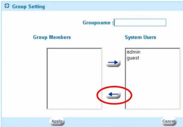
from the group. When complete, click the Apply button.
NAS Management
Manage the main functions of the shared storage from this menu.

HD Initialization Wizard
The first time you use the NAS, you may have to initialize the hard disk. The wizard provides an easy way to initialize the hard disk.
By enabling SMART, the NAS will report when the hard drive is about to fail. Your hard drive must support this feature.

The HD Power Management should be enabled to prolong the life of the hard drive. When there is no activity for the set time period, the hard drive will power down to conserve power, save wear and tear, and prevent the unit from building up unnecessary heat. When a user wants to access the storage, the NAS will automatically wake up.
The status will show Ready when the hard drive is initialized. Click on the Initialize button to begin the initialization process.
Click OK to the warning message to continue the process.

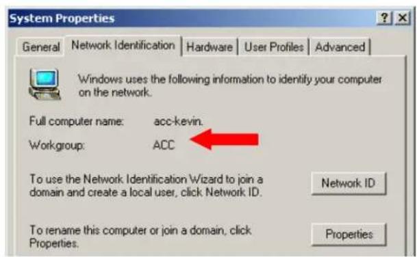
Enter the workgroup name, description and initial share folder name. The workgroup name should be the same one that the computers accessing the
NAS are on. Windows 2000/XP users can use a different workgroup name if desired. Click Next to continue.

You can find your workgroup name by right clicking on My Computer and selecting Properties.
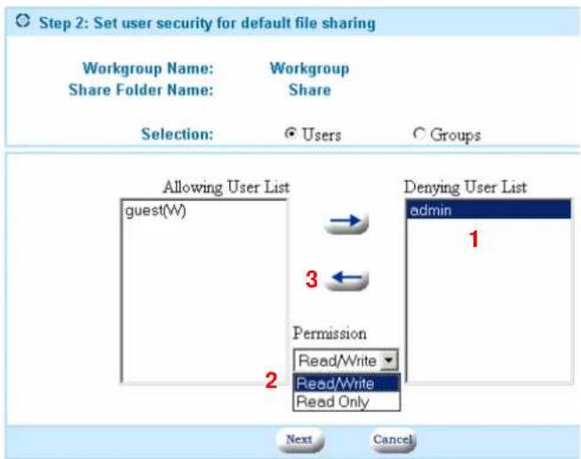
You must assign at least one user to this share folder. (1) Highlight the user
on the list to the right, (2) select the permission you want them to have: Read/Write or Read Only, (3) click on the ← button to move the user over to the Allowing User List.
Highlight users on the left list and select the button to remove them from the share or change their permissions.
Click Next to continue.
The progress of the initialization will be displayed.
Initialization - Hardisk Format Percentage : 81%
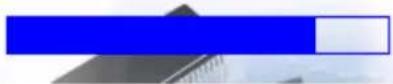
You can also view the progress by returning to the main wizard screen.

Once the initialization is complete, the status will change to Ready.

USB HD Information
Each of formatted partitions (FAT32, EXT2 and EXT3) on the attached USB storage drive will be shown in the USB HD information page. The naming rule for "Mounting path" is based on the connecting port. For example, if the USB hard drive was attached on port A and here are three formatted primary partitions on the disk, the SA will create "USBHDA1" and "USBHDA2" mounting path to represent each partition space.
| USB HD Info | |||
| USB Hardisk Information | |||
| PortA (Disk) Capacity: 38154 MB | |||
| Partition No | Total Size(MB) | Available Size(MB) | Mounting Path |
| 1(Primary) | 20481 | 18279 | USBHDA1 |
| 2(Primary) | 17665 | 16265 | USBHDA2 |
| PortC (Disk) Capacity: 19077 MB | |||
| Partition No | Total Size(MB) | Available Size(MB) | Mounting Path |
| 1(Primary) | 19069 | 16547 | USBHDC1 |
| Refresh | |||
Advanced Settings
All the file protocols settings are located here. Disable any protocols not in use by the computers on the network to increase performance. Most users will not need to change any of the settings. Make sure to click on Apply after making any changes.
Change the workgroup or NAS description. Workgroup name should be the same for all computers sharing files.
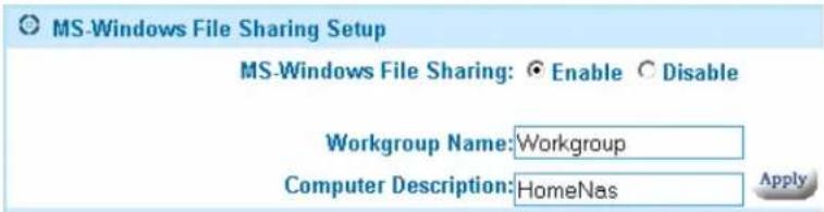
Enable Apple file sharing for compatibility with older Macs.

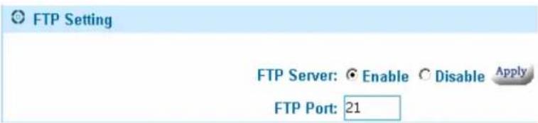
Enable the FTP server to allow remote and local FTP file access. Change the default FTP port 21 for added security or compatibility. Note: If you change
the default port, users must manually enter the new port number when trying to access the FTP server. See FTP Server chapter.
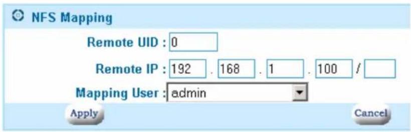
Linux users need to create NFS Mappings in order to connect to the NAS.
Enable the Network File System and click on Add to create the mapping.

Enter the Remote UID, IP, netmask and the local mapping user. Once complete, mount the share on the Linux machine. A typical mount command line
# mount
File Sharing
For file sharing, you must create users and groups first. Use this to organize the data on the NAS. You can create private and public folders. By managing
which users have access to the shares, users can only access information that they are allowed to. This access is the same whether they are accessing the share from the local network or through the Internet via F
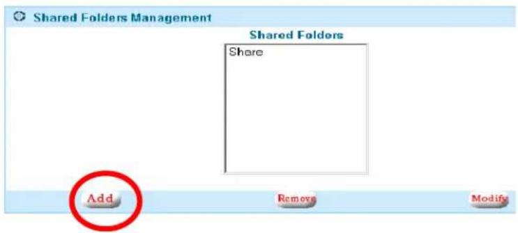
Click on Add to create a new shared folder.
Enter a share folder name
Assign users by highlighting the user, selecting the file permission and clicking on the or button.
Click on Apply when complete.
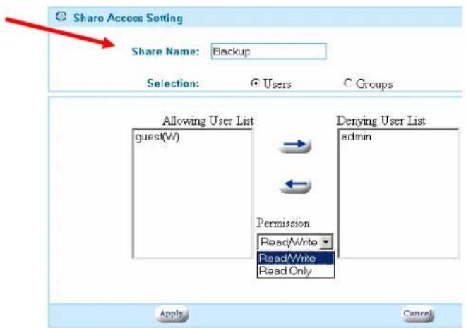
Highlight the share folder and click on Remove or Modify to delete or edit the shared folder properties.

USB Storage Sharing
As mentioned above, each partition of the attached USB storage will be presented to one shared folder. So, if one USB storage device be plugged into A port and it have 2 partitions. The system create the USBHDA1 and USBHDA2 automatically and assigned the guest have read/write permission by default.

FTP Server
If you want to access files stored on your NAS from a remote location, the included FTP server is the easiest way. Here is a typical setup:
Connection Diagram:
Work PC<-->Internet<-->DSL/Modem<-->Router<-->NAS
To access files from the NAS from a remote location, a static IP and/or a DNS name is required. You can also setup a DDNS account if you are using a dynamic IP (your DSL IP changes all the time). See Dynamic Domain Name
Server for additional information and help in setting up this service. Your router must have this feature or you may have to run a client software on a PC that is running on the network. You must set your router to forward port
21 to your NAS's fixed IP address. Refer to the DDNS and port forwarding/virtual server chapter of your router manual for details.
Enable the FTP server on the NAS.
You can change the default FTP port in the same configuration screen. This is useful for making you FTP server less visible to users whom you do not want to grant access. Some networks also block the standard port 21 and may require you to change to a different port. Note: If you change the default port 21, you will need to enter the port number every time you access the FTP server.
Make sure to have users and passwords assigned to all your shared folders. If you want to allow anyone access, just assign the 'guest' account to that folder. FTP users can then log on with and anonymous account to that folder.
Note: Users will be able to see the names of all the other shared folders, but will not be able to access them without a username and password. To completely disable anonymous access (must have user account on NAS to see folders), make sure you do not have the 'guest' account assigned to any shared folder.
Now from the remote location, type into a browser (or FTP application) ftp://
Personal Web Server
The Web Server settings are currently under 'Nas Management->Web Server'.
Getting started
Enable the web server by selecting the 'Enable' radio button. It will then create a shared folder called 'www'. Set the server port number to '80' if you want all default HTTP calls to go to your website. When you type in a URL address in a browser, the Internet automatically directs your browser to port 80 at that address. This is the industry standard and should be used 99% of the time. If you want to hide or make your site available only to people who know your port number, then you can assign it a different port. For example, if you were to assign port 77 instead of 80, users would have to type in their browser www.mywebsite.com:77 to see the website. You do not normally use ':80' because that's the assumed default in the industry.
Uploading your web page(s)
All web pages for your website will be stored in the ‘www’ shared folder. You can copy the folders and files of your website into that directory via the network neighborhood, mapped drive, or FTP if you have enabled that function. Make sure that you have allowed the user uploading the files to have read/write access under ‘File Sharing’. By default, anyone (anonymous) can have access to the ‘www’ shared folder as the guest account is assigned to that share.
Web page design
You must have an 'index.html' file as that is what the web server will look for as the first page of your website. You are free to make folders under the 'www' directory to help organize your website. All references to those directories can be called on from any page. You can use many popular web page design programs to make your website and then copy the finished product (all associated images, files and folders also) to the 'www' shared folder.
Accessing the website
Users with a static WAN IP address can access the website simply by typing in the IP address on any browser. If you are on the inside of the network, you must use the WAN IP address to access the website, not the internal appliance IP address. If you have a domain name, then you can have the domain name company forward the domain to this static IP address. With a domain name, you do not have to remember the IP address, just the domain name.
If you have a dynamic IP, you can setup a DDNS account and enable the DDNS feature of your appliance to make your website accessible without having to find out the current IP address. Refer to the DDNS Chapter for more information.
Important Note:
The ‘www’ share defaults to allow ‘guest’ users to have access. Please go into NAS Management -> File Sharing, add a valid user and remove ‘guest’ if you do not wish everyone to be able to modify you web pages.
E-mail Server
The E-mail Server settings are located under Nas Management->E-mail Server.
Getting started
In order to use the e-mail server, you must have a domain name or have registered with a DDNS service provider. E-mail requires a domain name and will not work with just an IP address. Enable the e-mail server by selecting the 'Enable' radio button. Enter your domain name in 'Mail Domain Name'. For example, myhomedomain.com is a valid name. Do not enter the 'www' usually associated with domain names. If you have a DDNS name, for example, myname.dyndns.org, you can enter it here in as shown also. You should limit the maximum size a mailbox under the quota field and the size of each e-mail in the following field. Default settings are '0' for unlimited.
E-mail names
After applying the settings, your e-mail accounts are now active. They are based on your user names that are created under user management. For example, if ‘teacher’ is a user on the appliance, and ‘school.com’ is the domain name, the e-mail address for ‘teacher’ is now ‘teacher@school.com’. DDNS e-mail addresses work in a similar manner. For example, if ‘teacher’ is the user on the appliance and the domain name (DDNS) is ‘school.dyndns.org’, then the e-mail address would then be ‘teacher@school.dyndns.org’.
Sending and receiving e-mail
You can use any POP e-mail type program to retrieve and send your e-mails.
Windows includes MS Outlook Express as a standard application. Start Outlook. Under Tools->Mail, you want to ADD a mail account. Enter a display name, the formal name you want your e-mails to appear to come from (Usually your full name). In the e-mail address field, enter your new e-mail address. From the above example, we would enter 'teacher@school.com' or 'teacher@school.dyndns.org'. Under 'Incoming mail server' and 'Outgoing mail server', enter your domain name. In the above examples, it would either be 'school.com' or 'school.dyndns.org'. Both fields should be the same. Lastly, enter the Account name and password. This name is the same one as on your appliance. In this case, user name is 'teacher' and password is: ****. Click on the 'Finish' and you are ready to send and receive e-mail!
NOTE:
Passwords are highly suggested for all e-mail account users to protect your e-mails and to prevent people from unauthorized use of your e-mail server.
Windows USB Printer Server
Standard USB 1.1 and 2.0 printers can easily be shared between Windows users on the network with the built-in USB printer server. Note: Some or all functions of multi-function printers may not work depending on the driver support by the respective printer manufacturers.
Please make sure the hard disk has been initialized. (the status is READY)

Connect a USB Printer to the USB port on the back of the NAS and turn it on.
Locate the NAS device in My Network Places and select it by double clicking on the icon.
Enter a valid user name and password when prompted.

You will now see the printer port next to the shares for the device.
Double click on the PortA printer icon and follow the instructions to install the printer driver at the local station. You may need to select 'Have Disk' and insert your printer's driver CD during the installation proc

Once the driver installation is completed, you should be able to select the printer from the printer list in any Windows application. You can manage the printer the same way as any other networked printer under Windows.
Appendix A
PPTP VPN (W2K and XP only)
Important:
Make sure that the subnet of your Appliance is different the network you are trying to connect from. For example: User's office IP addresses are 192.168.1.x, set your Appliance to 192.168.2.1 Netmask 255.255.255.0.
Make sure that you have created a user account and password on the Appliance for the users that you want to allow VPN access.
Proceed to your appliance's PPTP Settings under VPN Settings.
- Enable the Server
- Enter a server IP, a number from 2-254 that is not being used by any computer on the Appliance network. Usually 200 is a safe number.
- Enter a range of IP addresses that users logging into the Appliance will be assigned. Usually 201-210 is ok. Again make sure that there are no computers on the Appliance network using the IP addresses in this range.
- Select Apply.
From the remote computer:
- From the start menu: Select Settings -> Network and Dial-up Connections -> Make a new connection.
- Click Next on the wizard and select Connect to a private network through the internet. Click on Next.
- Select Do not dial.....Click Next
- Enter the host name. This should be a static IP if you have one. If not, then set up a DDNS account before continuing. This is where the Appliance can be found on the Internet. Click Next.
- Select if you want to create this connection for all users on your remote network or just for the one computer. Click Next.
- Name your connection and select if you want to have an icon on your
desktop. Click Finish when done.
- Use the user name and password on your Appliance to log in. You should be able to see the Appliance in your network neighborhood now. You must initiate the VPN connection each time unless you selected otherwise.
TIPS: If all you need is file transfer, we suggest using the FTP server feature, as it is faster and simpler. If you must use the PPTP VPN feature, then you can also disable the encryption under Properties -> Security to increase the performance.
Pinging
You can test your network connection in various situations with this very simple method.
From a command prompt, type in: ping
If there are replies, then there is a connection running between the two machines.
By pinging the device name, we also get the IP address of that device also.
![D:\>ping 192.168.1.14 Pinging 192.168.1.14 with 32 bytes of data: Reply from 192.168.1.14: bytes=32 time<10ms TTL=255 Reply from 192.168.1.14: bytes=32 time<10ms TTL=255 Reply from 192.168.1.14: bytes=32 time<10ms TTL=255 Reply from 192.168.1.14: bytes=32 time<10ms TTL=255 Ping statistics for 192.168.1.14: Packets: Sent = 4, Received = 4, Lost = 0 (0% loss), Approximate round trip times in milli-seconds: Minimum = 0ms, Maximum = 0ms, Average = 0ms D:\>ping nas Pinging nas [192.168.1.14] with 32 bytes of data: Reply from 192.168.1.14: bytes=32 time<10ms TTL=255 Reply from 192.168.1.14: bytes=32 time<10ms TTL=255 Reply from 192.168.1.14: bytes=32 time<10ms TTL=256 Reply from 192.168.1.14: bytes=32 time<10ms TTL=257 Ping statistics for 192.168.1.14: Packets: Sent = 4, Received = 4, Lost = 0 (0% loss), Approximate round trip times in milli-seconds: Minimum = 0ms, Maximum = 0ms, Average = 0ms D:\>](/content/2026/05/920977/images/52315d853e5d67a1022d20c14b0e5bb77dff1292f2076312841d33ad7eeee5a4.jpg)
Searching the Network for the NAS
If you are not able to locate the NAS in the Network Neighborhood or My
Network Places, you can try to search for it.
Click Search under My Network Places.
Enter the name of the NAS or the Fixed IP address if configured that way and click Search Now.

All other company and/or products names are trademarks and/or registered trademarks of their respective owners.

- Product Specifications
- Connection Sharing
- Virtual Private Network
- Firewall
- System Management
- Services
- Network
- PPP Authentication
- Real Time Clock
- File Sharing
- User Management
- Power Management
- Other Features
- Benefits and Key Features
- Easy Installation
- Network Attached Storage
- Dynamic DNS
- USB Print Server
- Personal Web Server
- Personal POP E-mail Server
- FTP Server
- - Power Down
- - Hard Disk Standby
- Physical Parts and Panel of the Smart Server
- WAN Port
- WAN MDI/MDIX Switch
- LAN Ports
- Reset Button
- Power Button
- Package Contents
- Quick Installation
- Hardware Installation
- Check Your PC First
- Connect to the Web-Based Manager
- Web-Based Manager – Basic Settings
- Internal Network Interface
- Domain Name Server
- External Network Interface
- Example 1: Fixed IP Address Settings
- Example 2: DHCP Client / Cable Modem
- Example 3: ADSL Connection
- Example 4: ADSL/PPTP Client Setting
- Configuration Hierarchy
- Network Settings
- DHCP Server
- ■ To Enable the DHCP Server
- If you do not have a DHCP server on your network,
- ■ To Disable the DHCP Server
- If you already have a DHCP server on your network,
- Or you do not have DHCP server on your network, but you would like to assign a static IP address to each device connected to the LAN port of SA.
- IP Alias
- Multiple NAT
- Route Settings
- DDNS
- Firewall Settings
- Virtual Server Settings
- URL Filter Setup
- IP Filter Setup
- Denial of Service
- VPN Settings
- PPTP Settings
- Administrator Settings
- Event Report Settings
- Firmware Update
- Select Browse and
- Time Settings
- SNMP
- System Reports
- System Information
- System Log
- URL Log
- DHCP Lease Report
- Users
- Groups
- NAS Management
- HD Initialization Wizard
- USB HD Information
- Advanced Settings
- USB Storage Sharing
- Getting started
- Uploading your web page(s)
- Web page design
- Accessing the website
- Important Note:
- E-mail Server
- E-mail names
- Sending and receiving e-mail
- NOTE:
- Windows USB Printer Server
- Appendix A
- PPTP VPN (W2K and XP only)
- Important:
- Pinging
- Searching the Network for the NAS
Brand : Intellinet
Model : 501705
Category : Server