
EXR6004 mini - Digital Video Recorder AVer - Free user manual and instructions
Find the device manual for free EXR6004 mini AVer in PDF.

| Product Type | Mini 4-channel Digital Video Recorder (DVR) |
| Brand | AVer |
| Model | EXR6004 mini |
| Dimensions (W×D×H) | Approx. 260 × 200 × 44 mm |
| Weight | Approx. 1.5 kg (without hard drive) |
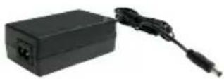
| Power Supply | 12 VDC, 2 A power adapter (power cord included) |
| Video Inputs | 4 channels: IP cameras (Network) or analog cameras (BNC) via adapter (not included) |
| Video Output | 1 VGA output, 1 HDMI output |
| Audio | 1 audio input (RCA), 1 audio output (RCA) |
| Storage | 1 bay for 3.5" SATA hard drive (not included), external storage via USB |
| Network | 2 Gigabit Ethernet ports (RJ45) |
| USB Ports | 2 USB 2.0 ports (mouse, keyboard, storage devices) |
| Alarms | 4 detector inputs, 1 alarm output |
| Main Functions | Continuous, scheduled, motion detection recording; remote access (WebViewer, CM3000); PTZ control; event search; video export (USB); snapshot (JPEG); multi-screen (1, 4); playback with fast forward/slow motion |
| Maintenance and Cleaning | Unplug power before cleaning; use a soft, dry cloth; do not use solvents or abrasive products |
| Safety | Do not expose to moisture, shocks, extreme temperatures; do not open the case (except for hard drive installation); administrator password protection |
| Spare Parts and Repairability | 3.5" SATA hard drive, 12V power adapter, USB mouse, cables; repair by qualified technician |
| General Information | Supplied with quick installation guide, software CD (manual included), USB optical mouse, power adapter, power cord, hard drive fixing bracket |
Frequently Asked Questions - EXR6004 mini AVer
User questions about EXR6004 mini AVer
0 question about this device. Answer the ones you know or ask your own.
Ask a new question about this device
Download the instructions for your Digital Video Recorder in PDF format for free! Find your manual EXR6004 mini - AVer and take your electronic device back in hand. On this page are published all the documents necessary for the use of your device. EXR6004 mini by AVer.
USER MANUAL EXR6004 mini AVer
© 2011 AVer Information Inc. All rights reserved.
No part of this document may be reproduced or transmitted in any form, or by any means without the prior written permission of AVer Information Inc. AVer Information Inc. reserves the rights to modify its models, including their characteristics, specifications, accessories and any other information stated herein without notice. The official printout of any information shall prevail should there be any discrepancy between the information contained herein and the information contained in that printout.
TRADEMARKS
“AVer” is a trademark owned by AVer Information Inc. Other trademarks used herein for description purpose only belong to each of their companies.
NOTICE
SPECIFICATIONS ARE SUBJECT TO CHANGE WITHOUT PRIOR NOTICE.
THE INFORMATION CONTAINED HEREIN IS TO BE CONSIDERED FOR REFERENCE ONLY.
WARNING
TO REDUCE RISK OF FIRE OR ELECTRIC SHOCK. DO NOT EXPOSE THIS APPLIANCE TO RAIN OR MOISTURE.
WARRANTY VOID FOR ANY UNAUTHORIZED PRODUCT MODIFICATION.
INFORMATION
For more information, please refer to the user manual in the software CD.
Table of Contents
Package Contents.... English-1
Hardware Installation .... English-2
A. Install Hard Disk.... English-2
B. Device Connection.... English-3
For the First Time Using the DVR Unit.... English-4
Familiarizing the Buttons in Preview Mode .... English-5
Familiarizing the Buttons in Playback Mode.... English-7
包裝內容物....繁體中文-1
硬體安裝....繁體中文-2
Hardware Installation ....German-2
TO REDUCE RISK OF FIRE OR ELECTRIC SHOCK. DO NOT EXPOSE THIS APPLIANCE TO RAIN OR MOISTURE.
WARRANTY VOID FOR ANY UNAUTHORIZED PRODUCT MODIFICATION.
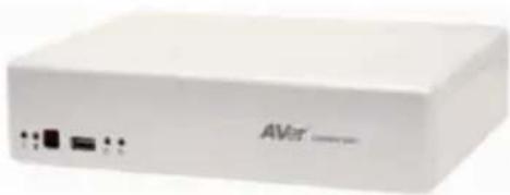
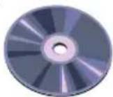
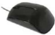
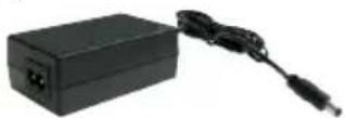
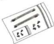
Package Contents
(1)
natural_image
White electronic device labeled 'AVR' with ports and indicator lights (no readable text beyond branding)(2)

(3)
(4)
(5)
(6)
(7)
(1) AVer ^TM EXR6004 Mini unit
(2) Quick Installation Guide
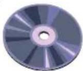
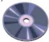
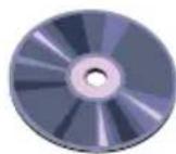
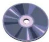
(3) Software CD (Manual is included)
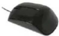
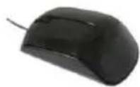
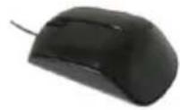
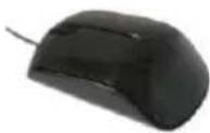
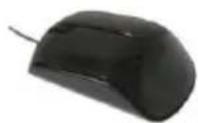
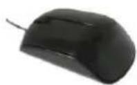
(4) USB optical mouse
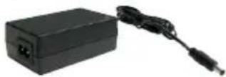
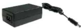
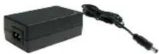
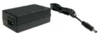
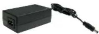
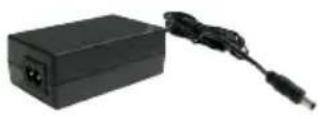
(5) Power Adaptor
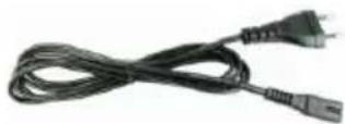
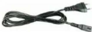
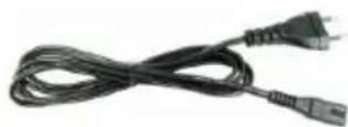
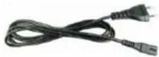
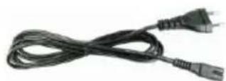
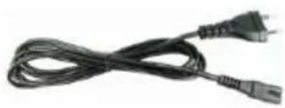
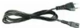
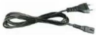
(6) Power Cord (*The power cord may vary according to the local electricity system.)
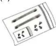
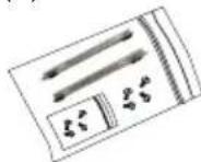
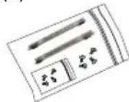
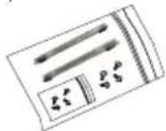
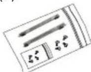
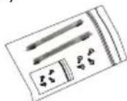
(7) HDD holder (including 8 screws)

If there is any damage, shortage or inappropriate item in the package contents, please contact with local dealer
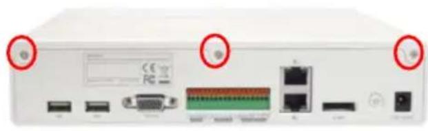
Hardware Installation
A. Install the hard disk

The DVR unit may include hard disk that depends on the model user has purchased. If the model user has purchased is included hard disk, user doesn't need to install the hard disk by yourself.
Follow the steps to install the hard disk:
- Loosen all screws
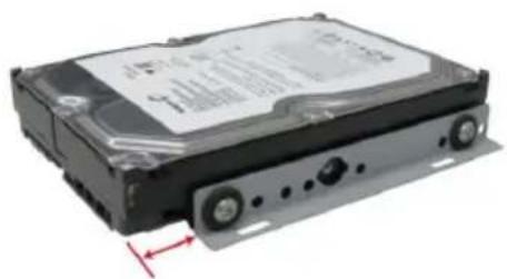
natural_image
Front view of a white electronic device rear panel showing ports, connectors, and a central connector (no readable text or symbols)- Secure the HDD holder on the hard disk. The position to screw the HDD holder on hard disk must same as figure shown. Otherwise, the hard disk won't be able to fit into inside the DVR unit.
natural_image
Exterior view of a hard disk drive (no visible text or labels)- Secure the hard disk inside the unit then place unit cover
natural_image
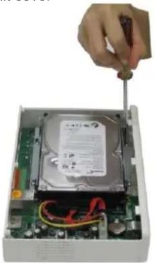
Hand inserting a screwdriver into a hard disk drive into an open circuit board (no visible text or symbols)- Push the cover backward and lift
natural_image
Two hands holding a white electronic device with red arrows indicating upward motion (no text or symbols visible)- Connect the SATA cable and the power connector to the hard disk
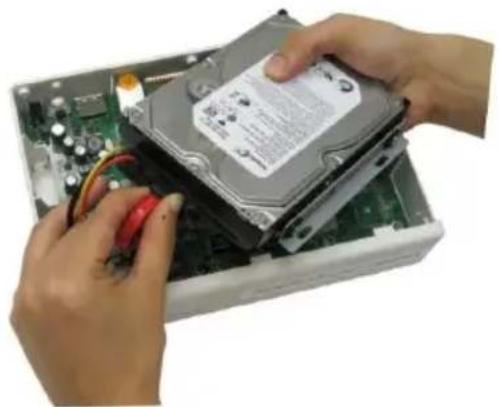
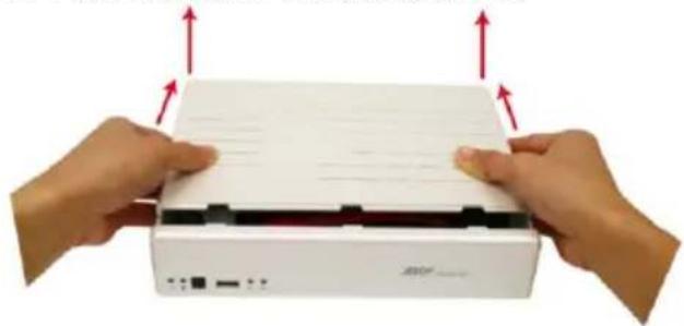
natural_image
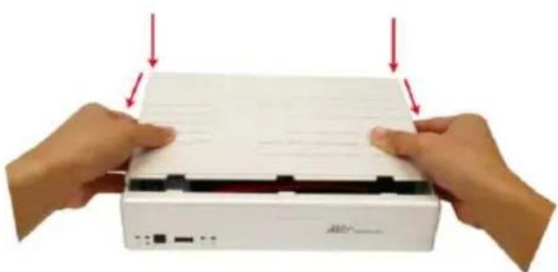
Close-up of hands installing a hard disk into an open computer motherboard (no visible text or symbols)- Push the cover forward and secure the cover
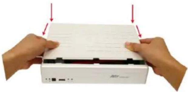
natural_image
Two hands pressing down on a white electronic device labeled 'Atr', with red arrows indicating compression or disassembly (no text or symbols on device body)- You may now connect all the cables. When the power is connected, the Power LED light turns on.

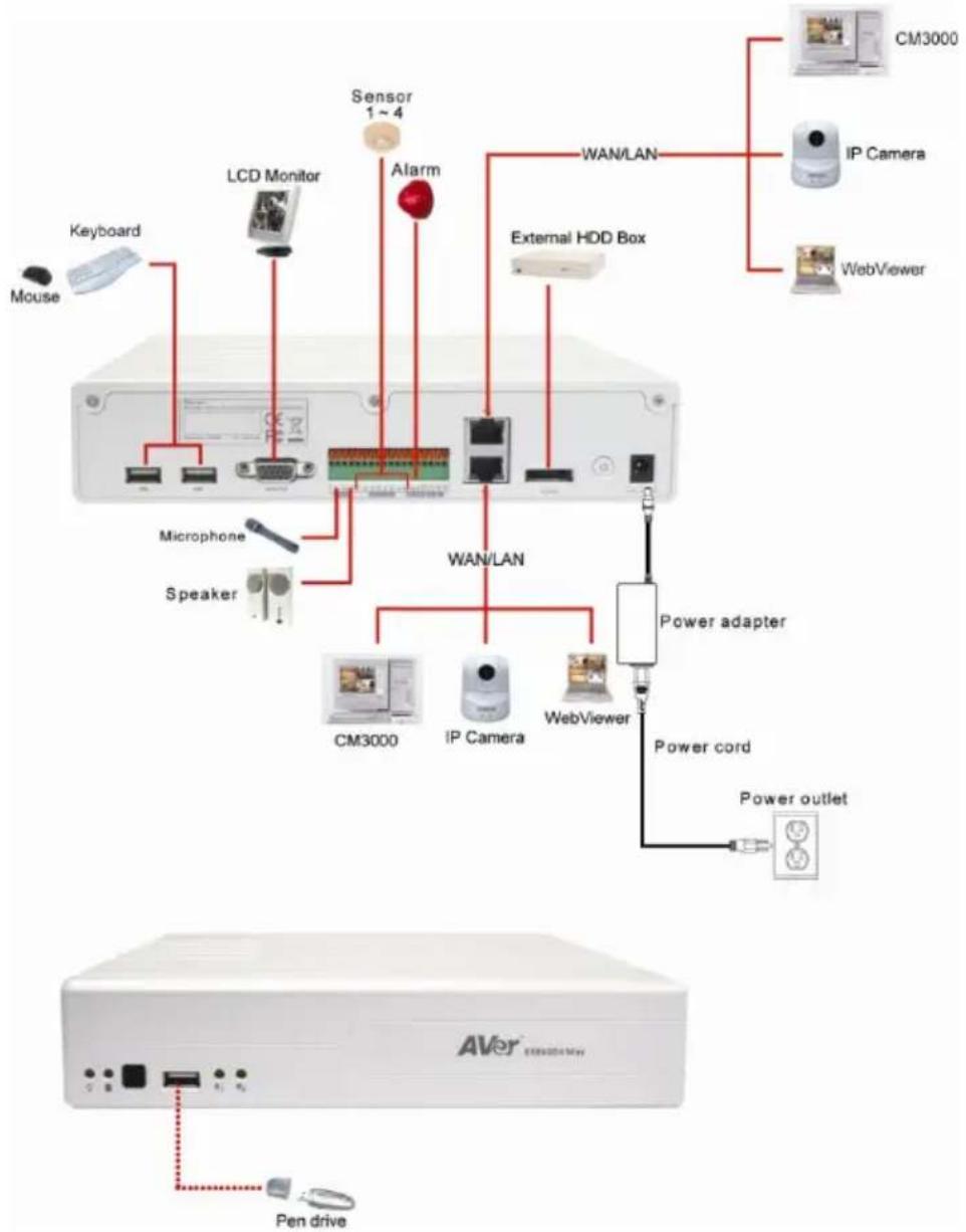
B. Device Connection
The back panel of the DVR unit, user can connect the 4 sensor devices, 1 alarm device, audio input/output device and an external HDD storage device. Through the dual Gigabit LAN ports can connect with the IP cameras and allows user to remote access the DVR server. The USB ports can connect the mouse and keyboard for more easily to operate DVR server.
Follow the illustration below to make the connection:
flowchart
graph TD
    A["Mouse"] --> B["Keyboard"]
    B --> C["LCD Monitor"]
    C --> D["Sensor 1~4"]
    D --> E["Alarm"]
    E --> F["WAN/LAN"]
    F --> G["External HDD Box"]
    G --> H["CM3000"]
    G --> I["IP Camera"]
    G --> J["WebViewer"]
    K["Microphone"] --> L["Speaker"]
    M["Power adapter"] --> N["CM3000"]
    M --> O["IP Camera"]
    M --> P["WebViewer"]
    Q["Power cord"] --> R["Power outlet"]
    S["AVER"] --> T["Pen drive"]
    U["External HDD Box"] --> V["External HDD Box"]
    W["CM3000"] --> X["IP Camera"]
    Y["WebViewer"] --> Z["Power adapter"]

Both two LAN ports can be connecting with IP camera and for remote accessing.
For the First Time Using the DVR Unit

The DVR system starts up will take a while, please be patient and wait.
Step 1. Connect the mouse to DVR unit(through USB interface).
Step 2. Power on the DVR unit. The preview UI will appear on the surveillance screen.

For security purpose, the DVR system would require you to enter User ID and Password before it can be accessed. (If this is the first time, enter the default ID [admin] and password [admin]).
Step 3. Formatting hard disk

If the hard disk has been format, skip this step.
a. Click Setup and enter the password
b. Click System → Add
c. Select the hard disk from device list and select Format type
d. Click Format button to start formatting
e. When formatting is done, click OK.
Step 4. Setup the date and time in order to have correct recording time and date.
a. Click Setup and enter the password
b. In Time section, click Setting button of System Time.
c. Select the date and adjust the time, and then, click OK.
Step 5. Connecting IP Camera
a. Click Setup → Camera
b. Select camera channel and type of camera – IP Camera
c. Then, enable the camera
d. Click IP Setting
e. Enable Protocol, and then, select protocol, mode, video format, and channel of IP camera.
f. Enter IP address or URL of IP camera.
g. Enter ID and password if IP camera's access authority is required. And then, click OK.
h. To connect another IP camera, follow the above steps.

User can download the newest IP camera patch on web site http://surveillance.aver.com/download-center > IP Camera > brand of IP camera > patches.
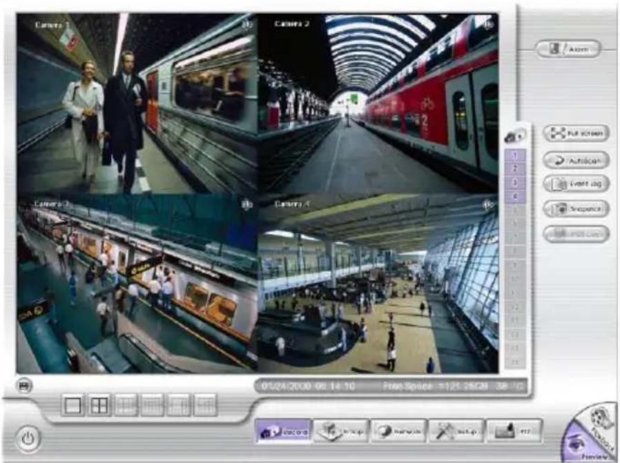
Familiarizing the Buttons in Preview Mode
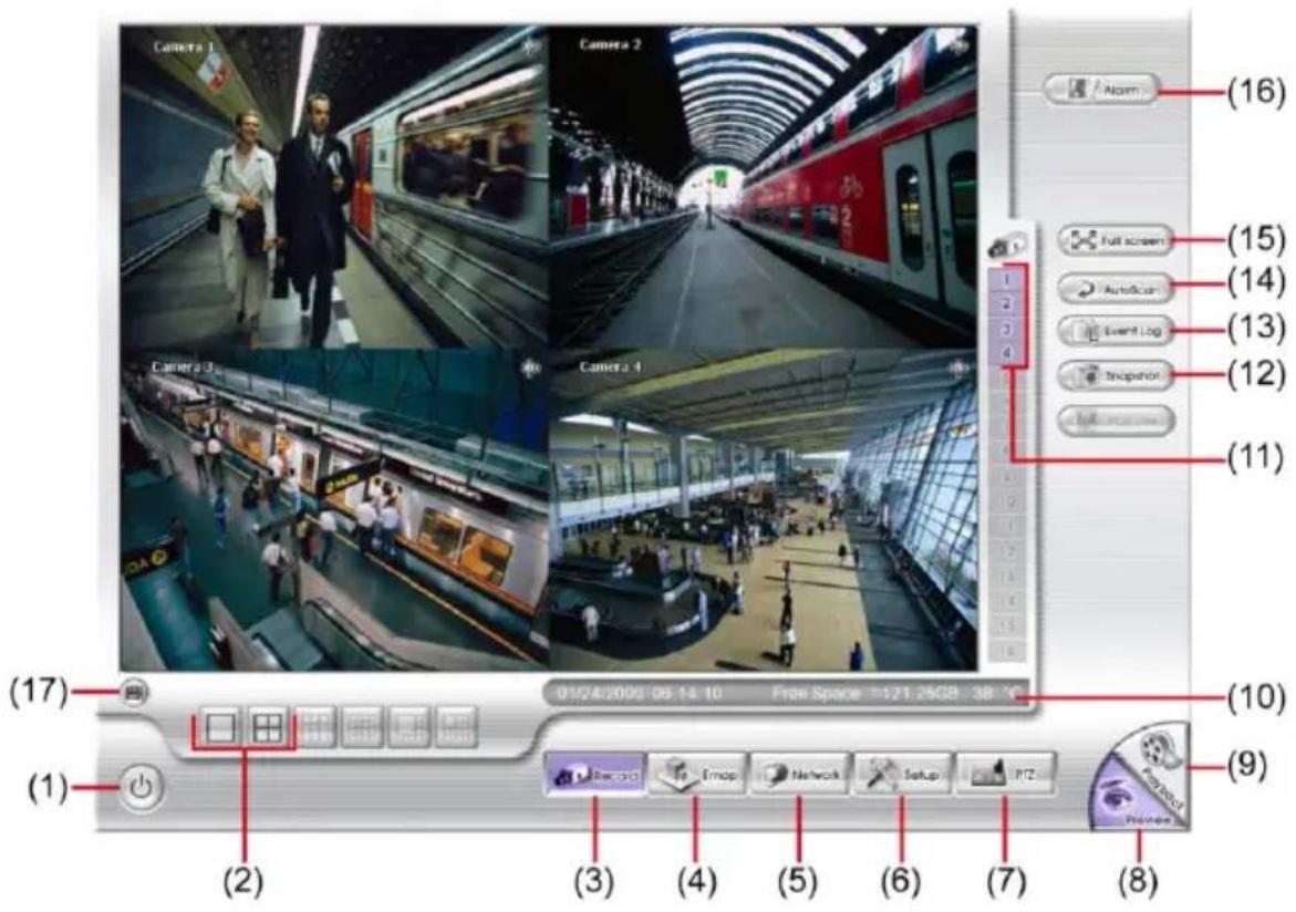
| Name | Function |
| (1) Logout | - Reboot: To restart the DVR system.- Power Off: To shutdown the DVR system.- Login: To login DVR system with different user account.- Cancel: Close the logout dialog box. |
| (2) Split Screen Mode | Select from 2 different split screen types to view all the camera, or one camera on a single screen.When user is in single screen mode, user can right-click and drag an area that you want to enlarge the view. Right-click on screen again will return to normal view. |
| (3) Record | Start/stop server and client site video recording. |
| (4) EMap | Display the map in each area, and the location of camera/ sensor/ relay and the warning. |
| (5) Network | Enable/disable remote system access. This feature allows you to access DVR server from a remote location via internet connection. The default is disabled. |
| (6) Setup | Configure the system settings. |
| (7) PTZ | Access PTZ control panel. |
| (8) Preview | Switch to Preview mode. This allows you to view live camera display. |
| (9) Playback | Switch to Playback mode. This allows you to view the recorded video file. |
| (10) Status bar | Display the recoding date, time and hard disk space of DVR unit. |
| (11) Camera ID | Show the number of cameras that are being viewed. When you are in single screen mode, click the camera ID number to switch and view other camera. |
| (12) Snapshot | Capture and save the screen shot in *.jpg format. |
| (13) Event log | Show the record of activities that take place in the system. |
| (14) AutoScan | Start/Stop video screen cycle switch. |
| (15) Full screen | View in full screen. To return, press the right button of the mouse or ESC on the keyboard or click the arrow icon. |
| When you switch to full screen in multiple-screen mode, Left click to toggle to only display one of the video in the multiple-screen mode or all. | |
| (16) Alarm | Click to view the alert and warning information. |
| (17) Virtual Keyboard | If the keyboard is not available, you may use the Virtual Keyboard. |
Familiarizing the Buttons in Playback Mode
To switch in Playback mode, click Playback button at the lower right corner of Preview mode user interface.
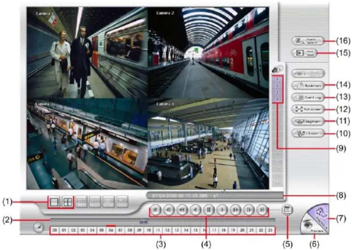
| Name | Function |
| (1) Split Screen Mode | Select from 2 different split screen types to playback the recorded video file of all the cameras or one camera on a single screen. |
| (2) Progress bar | Show the progress of the file being played. You may move the bar to seek at any location of the track. |
| (3) Hour Buttons | Select and click to playback the recorded video file on the specific time frame. |

The Hour buttons represent the time in 24-hour clock. The blue bar on top of the hour button indicates that there is a recorded video file on that period of time. While the red bar indicates that you are currently viewing the recorded video file.
| (4) Playback Control Buttons | Begin: Move at the beginning of the recorded video file.Previous: Go back to the previous frame.Slower: Play the recorded video file at the speed of 1/2X or 1/4X.Rewind: Wind back the recorded video file.Pause: Briefly stop playing the recorded video file.Play: Play the recorded video file.Faster: Play the recorded video file at the speed of 2X, 4X, 8X, 16X, 32X or 64x. |
| Name | Function |
| (4) Playback Control Buttons | Next: Go to the next frame.End: Go to the end of the recorded video file. |
| (5) Date | Select the date on the calendar and the time from 00 to 23 to where to start playing the recorded video file.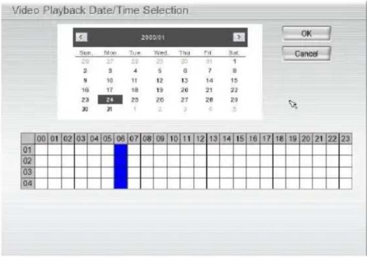 |

The numbers from 00 to 23 represent the time in 24-hour clock. The numbers from 01 to 04 represent the camera ID. The blue colored column indicates that there is a recorded video file on that period of time. While the red colored column indicates on where to start playing the recorded video file.
**For more information, please refer to the user manual in the software CD. If you still have inquiries, please go to http://surveillance.aver.com/technical-support.
| (6) Preview | Switch to Preview mode. |
| (7) Playback | Switch to Playback mode to view the recorded video file. |
| (8) Status bar | Display the recorded date, time and play speed. |
| (9) Camera ID | Show the number of cameras that are being viewed. When you are in single screen mode, click the camera ID number to switch and view other camera. |
| (10) Export | Export includes Snapshot, Output Video Clip, and Backup function.■ Snapshot: Capture and save the screen shot in *.jpg format.■ Output Video Clip: Save the segmented file in *.dvr format to external USB storage device.■ Backup: Save the playback file to USB device or DVD-ROM disk |
| Name | Function |
| (11) Segment | Keep a portion of the recorded video.1. Use the Playback Control buttons or drag the bar on the playback progress bar and pause on where you want to start the cut. Then, clickSegmentto set the begin mark. 2. Use the Playback Control buttons or drag the bar on the playback progress bar and pause on where you want to end the cut. Then, clickSegmentto set the end mark. To cancel segmentation or set the segment marks from the start, clickSegmentbutton again.[IMAGE]3. ClickExportbutton →Output Video Clipto save the video segment to the USB storage device. 2. Use the Playback Control buttons or drag the bar on the playback progress bar and pause on where you want to end the cut. Then, clickSegmentto set the end mark. To cancel segmentation or set the segment marks from the start, clickSegmentbutton again.[IMAGE]3. ClickExportbutton →Output Video Clipto save the video segment to the USB storage device. |
| (12) Full screen | View in full screen. To return, press the right button of the mouse orESCon the keyboard or click the arrow icon. When you switch to full screen in multiple-screen mode,Leftclick to toggle to only display one of the video in the multiple-screen mode or all. When you switch to full screen in multiple-screen mode,Leftclick to toggle to only display one of the video in the multiple-screen mode or all. |
| (13) Event log | Show the record of activities that take place in the system. To filter the records, select and click the option button to only display Event, System, Operation, Network or All. |
| (14) Bookmark | Mark a reference point when reviewing the recorded video file to which you may return for later reference.1. ClickBookmarkbutton2. In the Bookmark dialog box, you may do the following:-Addto create the new reference mark in the bookmark list.-Editto change the mark description.-Deleteto remove the selected reference mark in the list.-DeleteAllto remove all the reference marks in the list.-Exitto close Bookmark dialog box.3. Select and click one in the bookmark list to review the file. |
| (15) Find Next | Search for the next event or changes in the motion detector frame. You can use this when you are using Event Search function. |
| (16) Event Search | Search from the recorded activities that were recorded in event log (i.e., Sensor, Motion, Video Loss). |
注意
圓展科技公司保留規格最後變動權。
natural_image
White electronic device labeled 'AVer' with ports and indicator lights (no readable text beyond branding)(2)

(3)
(4)
(5)
(6)
(7)
natural_image
Front view of a white electronic device rear panel showing ports, connectors, and a battery (no readable text or symbols)natural_image
Exterior view of a hard disk drive with visible internal components and mounting base (no text or symbols)natural_image
Hand inserting a hard disk into an open computer motherboard (no visible text or symbols)natural_image
Two hands holding a white electronic device with red arrows indicating upward motion (no text or symbols visible)natural_image
Close-up of hands installing a hard disk into an open computer chassis (no visible text or symbols)- 將上蓋機殼蓋回並鎖上螺絲。
natural_image
Two hands holding a white electronic device with red arrows pointing to the top panel (no visible text or symbols)natural_image
White electronic device labeled 'Aler' with ports and indicator lights (no readable text beyond branding)(2)

(3)
(4)
(5)
(6)
(7)
natural_image
Front view of a network device rear panel showing ports, connectors, and a green connector (no readable text or symbols)natural_image
Exterior view of a black hard drive chassis with visible battery pack and mounting feet (no text or symbols)natural_image
Hand using a screwdriver to adjust the internal components of a computer drive into an open circuit board (no visible text or symbols)natural_image
Two hands holding a white electronic device with red arrows indicating upward motion (no text or symbols visible)natural_image
Close-up of hands installing a hard disk into an open computer chassis (no visible text or symbols)natural_image
Two hands pressing down on a white electronic device with red arrows indicating force or compression (no text or symbols visible)natural_image
White electronic device labeled 'AVar' with ports and indicator lights (no readable text beyond branding)(2)

(3)
(4)
(5)
(6)
(7)
Hardware Installation
natural_image
Front view of a network device showing ports, connectors, and a display (no readable text or symbols)natural_image
Exterior view of a hard disk drive with visible internal components and mounting holes (no text or symbols)natural_image
Hand using a screwdriver to adjust the internal components of a computer drive into a motherboard (no visible text or symbols)natural_image
Two hands holding a white electronic device with red arrows indicating upward motion (no text or symbols visible)natural_image
Close-up of hands installing a CD drive into an electronic circuit board (no visible text or symbols)natural_image
Two hands holding a white electronic device with indicator lights, showing internal components and red arrows indicating force or movement (no text or symbols visible)natural_image
White electronic device labeled 'AVI' with ports and indicator lights (no readable text beyond branding)(2)

(3)
(4)
(5)
(6)
(7)
natural_image
Front view of a network device showing ports, connectors, and a battery (no readable text or symbols)natural_image
Exterior view of a black hard drive chassis with visible internal components and mounting holes (no text or symbols)natural_image
Hand turning a hard disk into an open circuit board with visible internal components (no text or symbols)natural_image
Two hands pressing down on a white electronic device with red arrows indicating force or movement (no text or symbols visible)natural_image
Close-up of hands installing a hard disk into an open computer motherboard (no visible text or symbols)natural_image
Two hands holding a white electronic device with indicator lights, showing internal components and red arrows indicating force or movement (no text or symbols visible)natural_image
White electronic device labeled 'AVot' with ports and indicator lights (no readable text beyond label)(2)

(3)
(4)
(5)
(6)
(7)
natural_image
Front view of a network device showing ports, connectors, and a central port (no visible text or symbols)natural_image
Exterior view of a hard disk drive with visible internal components and mounting holes (no text or symbols)natural_image
Hand using a screwdriver to adjust the internal components of a hard disk drive into an open circuit board (no visible text or symbols)natural_image
Two hands pressing down on a white electronic device with red arrows indicating motion (no text or symbols visible)natural_image
Close-up of hands installing a CD drive into an open chassis (no visible text or symbols)natural_image
Two hands pressing down on a white electronic device with red arrows indicating force or movement (no text or symbols visible)natural_image
White electronic device labeled 'AVR' with ports and indicator lights (no readable text beyond branding)(2)

(3)
(4)
(5)
(6)
(7)
natural_image
Front view of a network device showing ports, connectors, and a display (no readable text or symbols)natural_image
Exterior view of a hard disk drive with visible internal components and mounting holes (no text or symbols)natural_image
Close-up of a hand using a screwdriver to adjust the internal components of a computer drive (no visible text or symbols)natural_image
Two hands pressing down on a white electronic device with red arrows indicating motion (no text or symbols visible)natural_image
Close-up of hands installing a hard disk into an electronic device chassis (no visible text or symbols)natural_image
Two hands holding a white electronic device with red arrows pointing to the top panel (no visible text or symbols)natural_image
White electronic device labeled 'AVor' with ports and indicator lights (no readable text beyond branding)(2)
(3)

(4)
(5)
(6)
(7)

natural_image
Front view of a white electronic device rear panel showing ports, connectors, and a display (no readable text or symbols)natural_image
Exterior view of a hard disk drive with visible internal components and mounting holes (no text or symbols)natural_image
Hand inserting a hard disk into an open circuit board with visible wiring (no text or symbols)natural_image
Two hands pressing down on a white electronic device with red arrows indicating motion (no text or symbols visible)natural_image
Close-up of hands installing a hard disk drive into an electronic circuit board (no visible text or symbols)natural_image
Two hands holding a white electronic device with red arrows pointing to the top panel (no visible text or symbols)Brand : AVer
Model : EXR6004 mini
Category : Digital Video Recorder