
LT60 - Battery charger AEG - Free user manual and instructions
Find the device manual for free LT60 AEG in PDF.

| Product Type | Smart charger for lead-acid batteries |
| Brand | AEG |
| Model | LT60 |
| Input Voltage | 230 V AC, 50 Hz |
| Input Current | 15 A |
| Output Voltage | 12 V / 24 V DC |
| Max. Charge Voltage | 12 V: 14.7 V; 24 V: 29.4 V |
| Max. Charge Current | 12 V: 5 A / 20 A / 60 A RMS; 24 V: 2 A / 10 A / 20 A RMS |
| Power Supply Function | 13.6 V ± 0.3 V, 30 A ± 2 A |
| Engine Start Assist | 12 V: 540 A max. (180 A for 5 seconds) |
| Recommended Battery Capacity (24h Comfort) | 240 Ah |
| Recommended Battery Capacity (Maintenance) | 880 Ah |
| Compatible Battery Capacity Range | 10 Ah - 600 Ah |
| Compatible Battery Types | Flooded lead-acid (WET), Maintenance-free (MF), AGM, Gel |
| Enclosure Protection | IP20 |
| Weight | 18.5 kg |
| Operating Ambient Temperature | -20 °C to +40 °C |
| Main Functions | Automatic 9-phase charging (diagnosis, desulfation, pre-charge, soft start, main charge CC/CV, analysis, equalization, maintenance), temperature compensation, power supply, engine start assist, battery type and charge current selection |
| Safety | Protection against short circuit, reverse polarity, overheating, overcurrent, overcharge; automatic shutdown if battery is defective |
| Maintenance and Cleaning | Clean with a soft, dry cloth; store cable properly; have cables replaced by qualified personnel |
| General Information | User manual included; available in multiple languages; suitable for 12 V / 24 V lead-acid batteries |
Frequently Asked Questions - LT60 AEG
User questions about LT60 AEG
0 question about this device. Answer the ones you know or ask your own.
Ask a new question about this device
Download the instructions for your Battery charger in PDF format for free! Find your manual LT60 - AEG and take your electronic device back in hand. On this page are published all the documents necessary for the use of your device. LT60 by AEG.
USER MANUAL LT60 AEG
GB Instructions for use Charger LT60
natural_image
Line drawing of a portable electrical testing machine with wheels and control panel (no text or symbols)DE - Seite 3
Read these instructions before using the charger. Follow all instructions and recommendations.
FR - Page 33
Ladevorgang stoppen....11
Temperatursensor verwenden....11
line
| Time | V | A | |------|-------|-------| | 1 | Low | Low | | 2 | High | Low | | 3 | Medium| Low | | 4 | Medium| Medium| | 5 | Medium| Medium| | 6 | Medium| Medium| | 7 | Medium| Medium| | 8 | High | Low |www.aeg-automotive.com18
TABLE OF CONTENTS
Introduction....20
Normal use....21
Contents 21
Technical data....21
Safety 22
Product Overview....24
Functions....25
Operation 26
Before use....26
Installing the handle 26
Connecting the device....26
Start charging 26
Stopping charging 27
Using the temperature sensor 27
Use jump start function (jump start mode) 27
Switching the display 27
Switching battery types 28
Power Supply function 28
Automatic temperature adjustment....28
Completing charging and disconnecting the charger 28
Charging time....29
Charging phases....29
Charging current 30
12 V: slow charging....30
24 V: slow charging 30
Jump start function 30
Safety functions 30
Troubleshooting....31
Cleaning, care and maintenance....31
Service 32
Disposal....32
INTRODUCTION
Explanation of symbols and signal words used in these operating instructions and/or the device:

Refer to operator's manual

Risk of bodily or fatal injury to children!

Attention - Danger! Follow safety instructions and warnings!

Danger of electric shock!

Only use device in locations protected from weather!

Double-insulated casing (Protection Class I)

Consider the environment when disposing of the packaging!
Note:
These instructions also refer to the battery charger as device.
Normal use
The charger is intended for charging open and a variety of closed, maintenance-free lead-acid rechargeable batteries (batteries) as found in cars, boats, lorries and other vehicles, e.g.:
wet batteries (WET)
Lead-acid batteries (liquid electrolyte)
●el batteries (gel-type electrolyte)
▲GM batteries (electrolyte inside absorbed glass matt)
The charging device can be directly connected to the batteries using the clamps.
The charger further has a Power Supply function for replacing the battery or working on the vehicle's electronics.
The charging devices is not intended for charging battery types not listed above.
This device is not intended for use by children or persons with limited mental capacity or lacking experience and/or lacking expertise. Children should be supervised to ensure they do not play with the device.
Any other use or modification of the device is considered improper and involves significant risks. The manufacturer assumes no liability for damages due to improper use.
Contents
Please check the contents immediately after opening the package. Check the device and all parts for damage. Do not operate a defective device or parts.
T60 Charger incl. clamp terminal connection cable
Temperature sensor connection cable
screws 3x 15 mm
Handle
Instructions for use
Please include all relevant documentation to other users!
Technical data
| Model LT60 | |
| Item number 10091 | |
| Input 230 V AC, 50 Hz | |
| Input current 15 A | |
| Output 12 V / 24 V DC | |
| Charging voltage (max.) | 12 V: 14.7 V24 V: 29.4 V |
| Charging current +/-10 % 12 V | --- 5 A / 20 A / 60 ARMS24 V = 2 A / 10 A / 20 ARMS |
| Power supply 13.6 V | --- 30 A |
| Jump start function 12 V | --- 540 A max.180 A (5 seconds) |
| Recommended battery capacity (24h comfort) | 240 Ah |
| Recommended battery capacity for maintenance | 880 Ah |
| Ambient temperature | -20 °C till +40 °C |
| Type of batteries | lead-acid batteries(WET, MF, AGM and GEL) |
| For batteries with a capa-city (recommended) | 10 Ah - 600 Ah |
| Housing protection IP 20 | |
| Weight 18.5 kg |
SAFETY
General Safety Guidelines
Read all safety guidelines and instructions. Non-compliance with safety guidelines and instructions can cause electric shock, fire and / or serious injury. Keep all safety guidelines and instructions for future reference.
Also pass on documentation to other users and subsequent owners of the device!

Warning!

Life-threatening danger to infants and children! Never leave children unsupervised with the packing material as this can cause suffocation. Do not allow children to play with cables – strangulation hazard! Do not allow children to play with the components or fasteners, as they could be swallowed and result in suffocation.
The manufacturer is not responsible for damages caused by:
Improper connection and / or operation.
■Exterior force, damage to the device and / or damage to parts of the device caused by mechanical impact or overload.
Any type of modification to the device.
Use of the device for purposes that are not described in this instruction manual.
●consequential damages caused by non-intended and / or improper use, and / or defective batteries.
Moisture and / or insufficient ventilation.
The unauthorised opening of the device.
This will void the guarantee.

Risk of chemical burns!
Batteries contain acid, which could damage the eyes and skin. Charging batteries further generate gasses and vapours hazardous to the health.
Avoid any contact with caustic battery acid. Immediately thoroughly flush skin and any objects which have come into contact with acid. If eyes have come into contact with battery acid, flush eyes with running water at least 5 minutes. Contact your physician.
Use safety goggles and acid-proof safety gloves. Protect clothing, e.g. with an apron.
Never tip the battery, as acid may leak.
▲Always ensure adequate ventilation.
Do not inhale emerging gasses and vapours.


Explosion and fire hazard!
- caseous hydrogen (detonating gas) may form when charging the battery. Contact with open fire (flame, embers, sparks) may result in explosions.
Never charge the battery close to an open fire or in places where sparks may occur.
Always ensure sufficient ventilation.
Be sure the supply voltage matches the input voltage specified on the device (230 V AC) to prevent damage to the device.
Only connect and disconnect the battery connecting cables when the charger is disconnected from the mains.
Do not cover the device whilst charging, as it may be damaged from extreme heating.
Immediately stop using the device if you notice smoke or an unusual odour.
Do not use the device in rooms where explosive or flammable substances are stored (e.g. petrol or solvents).

Risk of electrical shock!
Chargers may interfere with the operation of active electronic implants, e.g. pacemakers, thus pose a personal hazard.
Avoid pouring or dripping water or other liquids over it. If water penetrates electrical devices, the risk of electric shock increases.
■ Ensure that all plugs and cables are free of moisture. Never connect the device to the mains with wet or moist hands.
Never touch both connections at once when the device is in uses.
Unplug from mains before connecting or disconnecting the charging cable with the battery, or when the device is no longer being used.
Remove all device cables from the battery before attempting to drive your vehicle.
▲Always unplug device by the plug. The cable may be damaged.
Do not use device if damaged. Damage to the power cable, the device or the charging cable increase the risk of electrical shock.
Do not attempt to disassemble or repair the device. Immediately have a defective device or damaged power cable repaired or replaced by a speciality shop.
Risk of short circuits! Do not allow the two connectors from the charging cable to touch if the power plug is plugged into the power outlet. Be sure not to connect the connectors or the battery poles through conductive objects (e.g. tools).
Never use the cable to carry or pull the device.

Risk of injury!
Never attempt to charge non-rechargeable, damaged or frozen batteries.
Do not use this device to charge dry cell batteries. These could burst, resulting in personal injury and property damage.
Please read and follow the operating manual and all safety instructions for the batteries to be charged and the vehicle before using this device.
Risk of damage!
Never place the device over or near the battery to be charged. Gasses from the battery could damage the unit. Place the device as far from the battery as the connecting cable will allow.
Never operate the device if it has been dropped or damaged in any other way. For inspection and repair, take it to a qualified electrician.
PRODUCT OVERVIEW
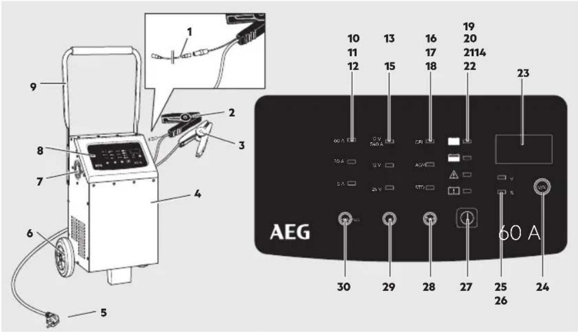
| No. | Description Function | |
| 1 | Temperature sensor connection cable To connect the automatic temperature adjustment | |
| 2 | Terminal connection cable (-) with clamp (black) | To connect the charger to the battery (- terminal) |
| 3 | Terminal connection cable (+) with clamp (red) | To connect the charger to the battery (+ terminal) |
| 4 | Housing Metal housing with louvres | |
| 5 | 230 V power plug For connecting to a 230 V mains socket | |
| 6 | Transport wheels For transporting the device | |
| 7 | Fan for cooling the charging electronics | |
| 8 | Display For operating the device | |
| 9 | Handle For pushing the device | |
| 10 | 60 A / LED red max. charging current: 12 V: 60 A / 24 V: 30 A | For charging high capacity batteries (e.g. marine or large deep-cycle batteries) or to quick-charge medium capacity batteries. |
| 11 | 20 A / LED blue (max. charging current: 20 A) | For charging medium capacity batteries (e.g. for lorries or tractors) |
| 12 | 5 A / LED green (max. charging current: 5 A) | For charging medium capacity batteries (e.g. for lawn tractors, snowmobiles or motorcycles) |
| 13 | 12 V / LED red Helps start vehicles and equipment with a weak battery. | |
| 14 | 12 V / LED blue For charging 12 V batteries | |
| 15 | 24 V / LED blue For charging 24 V batteries | |
| 16 | GEL / LED red for gel electrolyte batteries | |
| 17 | AGM / LED red for absorbed glass mat batteries | |
| 18 | STD (Standard) / LED red for batteries with liquid electrolyte (WET) and maintenance-free lead-acid batteries (MF) | |
| 19 | Full / LED green Lights up once the connected battery is fully charged. | |
| 20 | Charge / LED orange Lights up during the charging process.Flashes when in Power Supply mode. | |
| 21 | Error / LED red | Lights up if the battery is connected incorrectly (reversed pole). |
| 22 | Bad Battery / LED red | Lights up if the connected battery is defective. |
| 23 | Display Shows the battery's charging current or the charge condition. | |
| 24 | „V / %“ button for switching the display | |
| 25 | V / LED red Charging voltage | |
| 26 | % / LED red Battery charge condition | |
| 27 | Button Ⓐ to start and stop the selected function (indicated by LED) | |
| 28 | TYPE button for switching the battery type (indicated by LED) | |
| 29 | MODE button for switching the charging voltage (indicated by LED) and activating power supply | |
| 30 | MODE button for switching the charging current (indicated by LED) | |
Functions
The charger is equipped with a microprocessor (MCU - Micro Computer Unit) and features fully automatic charging-, diagnostic-, emergency- and maintenance functions. If the wrong battery voltage is set or the battery is defective, it will not charge and the "Error" LED (21) will light up (also see "Troubleshooting").
The "trickle charge" function allows the charger to be permanently connected. A full charge will be maintained.
The „Automatic Temperature Adjustment“ function measures the battery temperature and with the connection cable connected, adjusts the charging phases to the battery temperature. If the connection cable is not connected, standard charging of 9 levels will be used.
The „Power Supply“ function supplies your vehicle with a constant voltage of 13.6 V±0.3 V and a constant current of 30 A±2 A whilst working on the electronics or changing the battery.
OPERATION
Before use

Caution!
Risk of injury whilst unpacking due to e.g. pinching or falling pieces. Remove the charger from the packing with two people and watch for moving and loose parts.
Installing the handle
Note: You will need a cross-tip screwdriver for assembly.
- Remove the screws on the handle (9) for transport.
- Flip the handle up and secure the handle with two screws at each side.

Warning!
Before using this device be sure to read the operating manual for the battery and the vehicle and understand all safety notices.
Use safety goggles and acid-proof safety gloves.
- Ensure adequate ventilation.
■ Ensure the battery poles are clean. If the battery has removable vent caps, fill each battery cell with distilled water to the level recommended by the battery manufacturer. Do not overfill the cells.
If the battery must be removed from the vehicle before charging, always disconnect the earthed connector from the battery first. Also ensure all other loads in the vehicle are off.
If the battery does not have caps, refer to the manufacturer instructions on charging and the charging speed.
Connecting the device
- Connect the red (+) terminal connection cable with clamp (3) to the positive battery terminal.
- Connect the black (-) terminal connection cable with clamp (2) to the negative battery terminal.
Note:
The black (-) clamp can also be connected to the vehicle chassis (Please refer to the auto maker's instructions!). Be sure both clamps have good contact and are securely seated.

Warning!
Risk of fire and electric shock! If possible, connect the charger to the 230 V power socket without extension cable. In exceptions, use the shortest possible undamaged and unrolled 230 V extension cable.
- Plug the charger plug into a 230V power socke.
The LED will light up
5 A (green)
12 V (blue)
STD(red)
The display shows the current battery voltage. 10 seconds after starting, the „Charge“ LED (20) will light up and the charging voltage will be at the preset lowest charging rate.
If the battery is recognised to be defective or connected with the poles reserved the "Error" (21) or "Bad Battery" (22) LED will light up. In this case, unplug the charger and check the battery and the correct connection (also see "Troubleshooting").
-
Verify the device's preset charging voltage (12 V or 24 V) corresponds with the connected battery. If the charging voltage is too high, the connected battery may be damaged/destroyed.
-
You may repeatedly press the MODE button (29, 30) during charging to select the charging voltage and the charging current (see „Charging Current“).
-
Whilst charging you can press the TYPE button (28) several times to select the battery type (see „Switching Battery Types“).
Start charging
- Repeatedly press the TYPE (28) button to select the battery type. The LED (15, 16, 18) indicates the selection.
- Repeatedly press the MODE (29) button to select the respective charging current 12 V or 24 V. The LED (14, 15) indicates the selection.
- Repeatedly press the MODE (30) button to select the respective charging current. The LED (10, 11, 12) indicates the selection.
- Press (27) button to start charging. The "Charge" (20) LED will light up throughout the charging process.
- The battery is fully charged when the "Charge" (20) LED goes out. The display indicates the battery condition as 100 % and the "Full" (19) LED lights up.
Note:
Once the battery is fully charged, the charger will switch to trickle charge to maintain the charging status and protect the battery from overcharging.
Stopping charging
Press the Ⓐ (27) button.
Using the temperature sensor
The charger can measure the battery temperature and adjust the charging phase to the battery temperature.
- Connect the cable for the temperature sensor (1) to the charger.
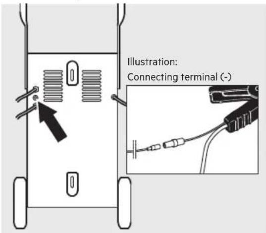
Illustration: LT60 back panel
-
Plug the cable for the temperature sensor (1) into the designated connection on the black (-) terminal connection cable with clamp (2).
-
Plug the charger plug into a 230V power socket.
-
Start the charging process (see „Start charging“).
Use jump start function (jump start mode)
The charger's jump start function (13) can be used to help start vehicles with a weak battery. In very low temperatures or if the battery voltage is below 8.5 V charge the battery at least 5 minutes before jump starting.
- Connect the charger as described under "Connecting the device".
- Repeatedly press the MODE (29) button to select jump start mode 12V (13).
- Press the button Ⓐ (27) to switch to Jump Start mode.
Note: The Jump Start mode can only be used with a connected battery.
The display shows the current battery voltage. The battery will be charged at 5 A until the engine is started.
Note:
The jump starting mode will automatically stop after approx. 30 seconds to prevent damage to the device.
Attention!
Do not turn the ignition for more than 5 seconds at a time.
- Try starting the vehicle.
Note:
Try starting for max. 30 seconds. Wait approx. 3 minutes before trying to start it again to allow the charger and battery to cool down.
- Press the button Ⓐ (27) to stop the Jump Start mode
Switching the display
During the charging process you can repeatedly press the „V / %“ button (24) to display the following parameters:
▼ = charging voltage
%= battery charge condition
Before charging only the current battery voltage can be displayed, and after charging only the battery charge condition.
Switching battery types
- TD = for batteries with liquid electrolyte (WET), maintenance-free lead-acid batteries (MF) and enhanced-flooded batteries (EFB)
AGM = absorbed glass mat batteries
GEL = gel electrolyte batteries
Power Supply function
Whilst changing the battery or working on the electronics the charger will supply the vehicle with power (13.6 V±0.3 V, 30 A±2 A) so no data will be lost.
- Connect the charger to the battery terminal.
- Plug the charger plug into a 230V power socket.
- Press the MODE button (29) for 3 seconds.
The „Charge“ LED (20) will light up. A voltage of 13.6V will be indicated in the display.
You can now work on the electronics. To exit the function, see item 6.
- Remove the battery.
- Insert a new battery.
- Press the button ① (27) to stop using the Power Supply function.
- Unplug from the 230V power socket.
- Separate the charger from the battery terminal.
Automatic temperature adjustment
| Automatic temperature adjustment | 12 V±0.2 V | ||
| GEL AGM STD | |||
| 5°C ± 5°C 14.65 V 15.25 V 15 V | |||
| 10°C ± 5°C 14.5 V 15.1 V 14.85 V | |||
| 15°C ± 5°C 14.35 V 14.95 V 14.7 V | |||
| 20°C ± 5°C | 14.2 V | 14.8 V | 14.55 V |
| 25°C ± 5°C | 14.05 V | 14.65 V | 14.4 V |
| 30°C ± 5°C | 13.9 V | 14.5 V | 14.25 V |
| 35°C ± 5°C 13.75 V 14.35 V 14.1 V | |||
| Automatic temperature adjustment | 12 V ± 0.2 V | ||
| GEL AGM STD | |||
| 5°C ± 5°C | 29.3 V 30.5 V 30 V | ||
| 10°C ± 5°C | 29 V 30.2 V 29.7 V | ||
| 15°C ± 5°C 28.7 V 29.9 V 29.4 V | |||
| 20°C ± 5°C | 28.4 V 29.6 V 29.1 V | ||
| 25°C ± 5°C 28.1 V 29.3 V 28.8 V | |||
| 30°C ± 5°C | 27.8 V | 29 V | 28.5 V |
| 35°C ± 5°C | 27.5 V | 28.7 V | 28.1 V |
Completing charging and disconnecting the charger
- First, remove the plug from the 230V power socket.
- Disconnect the black (-) terminal connection cable (2) from the negative battery terminal.
- Disconnect the red (+) terminal connection cable (3) from the positive battery terminal.
CHARGING TIME
A battery's charging time greatly depends on its charge condition, capacity and temperature.
Charging time in hours (approx.)
| Output 12 V / 24Battery size | V 12 V 24 V | |||
| Charging current(max.) | 5 A 20 A 60 A | 30 A | ||
| 10 Ah 2 0.5 - - | ||||
| 25 Ah 6 1.5 - 1 | ||||
| 50 Ah 12 | 3 | 1 | 2 | |
| 100 Ah | 25 | 6 | 2 | 4 |
| 150 Ah | 37 | 9 | 3 | 6 |
| 200 Ah | - | 12 | 4 | 8 |
| 300 Ah | - | 19 6 | 12 | |
| 400 Ah | - 25 | 8 16 | ||
| 600 Ah | - | 37 | 12 | 25 |
CHARGING PHASES

line
| Time | Signal A | Signal V | |------|----------|----------| | 1 | 0 | 0 | | 2 | 0 | 0 | | 3 | 0 | 0 | | 4 | 0 | 0 | | 5 | 0 | 0 | | 6 | 0 | 0 | | 7 | 0 | 0 | | 8 | 0 | 0 |The concept of the charging process is explained based on a 12 V battery.
Diagnosis
Diagnostic function which automatically checks the battery status and recognises the voltage.
| Voltage | Function |
| 0 V bis 1.5 V | “Error” LED (21) lit. Battery defective. |
| 1.5 V bis 12 V | Charging starts. |
| 12 V bis 13 V | Maintenance charging starts. |
| 14.6 V | Battery fully charged. “Full” LED (19) lit. |
| >15 V | “Error” LED (21) lit. |
Step 1: Condition check
The charger checks the battery condition and calculates the required charging parameters.
Step 2: Desulphation (rescue)
The charger can rescue most drained batteries with voltages up to a minimum of 1.5 ± 0.5 V.
The safety switch does not allow the charger to start charging if the voltage is below 1.5 ± 0.5 V.
At a voltage range of 1.5 ± 0.5 V to 10.5 ± 0.5 V the charger will initiate pulse charging.
the voltage rises above 10.5 ± 0.5 V, the charger will switch to the previously selected regular charging mode, which will charge faster and more safely.
Step 3: Precharging
The battery is gently charged with a low charging current to return the battery to a chargeable state.
Step 4: Soft start
The battery is gently charged with a low charging current.
Step 5: Base charge with a constant current
The battery is quickly and safely charged with a consistent current.
Step 6: Base charge with a constant voltage
The battery is charged at a constant charge end voltage until it is fully charged.
Step 7: Analysis
Once the battery is fully charged, the charging process will stop.
Step 8: Equalisation charge
If the battery is fully charged and drops to 12.8V within 2 minutes, another charging process will begin automatically.
Step 9: Maintenance charging
The charger monitors the battery capacity. Once the battery falls below 12.8 V, the charger will emit a charging pulse. This maintains the battery's highest possible charging level.
Jump Start mode
If the connected battery has less than 14.7 V, first a charging process will automatically be used before the device switches to Jump Start mode. When pressing and holding the button (27) for 3 seconds the charger will directly switch to Jump Start mode without charging.
CHARGING CURRENT
12 V/5 A and 24 V/20 A: Intended Use
To charge low and medium capacity batteries (12 V/24 V) (e.g. lorries or tractors).
12 V/60 A and 24 V/20 A: Intended Use
For charging high capacity batteries (e.g. marine or large deep-cycle batteries) or to quick-charge medium or higher capacity batteries.
Jump Start: Intended Use
Helps start vehicles and equipment with a weak battery.
12 V: slow charging
| Model | Charging voltage (V) | Charging current (A) |
| LT60 12 V | 5 A / 20 A / 60 A RMS |
24 V: slow charging
| Model | Charging voltage (V) | Charging current (A) |
| LT60 24 V | 2 A / 10 A / 20 A RMS |
Jump start function
| Model | Charging voltage (V) | Charging current (A) |
| LT60 12 V 540 A |
SAFETY FUNCTIONS
The charger features the following safety features to prevent damage to the charger and the battery or the vehicle:
Short circuit (defective battery),
incorrect connection (connected with reversed polarity),
●overheating
excess current
overcharging
TROUBLESHOOTING
| Error/Problem Possible cause Correction | ||
| The LED (22) will light up. | Defective battery:Battery voltage is under 1.5 V | Have the battery checked by a speciality repair shop.Replace battery. |
| LED (21) will light up. | Battery incorrectly/not connected Unplug charger and check the connections. | |
| Battery cannot be charged No | power supply, charger not plugged in. Verify the charger is plugged into a 230 V mains outlet and the “Power” LED is on.Battery may be defective | |
| Long charging time Only a very low charging current is used in very low temperatures (below 0 °C).This will extend the charging time. As the battery warms up, the charging current is adjusted accordingly. | Charge battery in normal conditions.Explosion hazard!Never charge frozen batteries. | |
| Battery capacity too high for the charger being used. | ||
| Battery voltage too low Battery wasn’t charged long enough. Ensure the battery is charged long enough. | ||
CLEANING, CARE AND MAINTENANCE
Caution!
Caution! Risk of electric shock. Always first unplug the 230 V power plug (5).
●clean clamps after every charging. To prevent corrosion, wipe off any battery fluid which may have come into contact with the clamps.
Carefully wind the cable when storing the device. This will help prevent accidental damage to the cable and the device.
●clean the product with a soft, dry cloth.
Store the machine in a clean, dry place.
Caution!
Only qualified technical personnel should change the plug or the connecting cables. This will guarantee the safety of the device is maintained. If the product is no longer suitable for use dispose of it in an environmentally friendly manner in accordance with your local ordinances.
32 www.aeg-automotive.com
Service
Should you have any questions regarding commissioning or operating in spite of studying these operating instructions, or if a problem should occur against all expectations, please get in contact with your specialist supplier.
Disposal
The packaging consists of non-contaminating materials that you can dispose of at your local recycling point.

Do not throw electrical appliances in with domestic waste!
In accordance with European Directive 2012/19/EC for waste electrical and electronic equipment (WEEE) and conversion to national law, used electrical appliances must be collected separately and taken to a recycling point. For ways to dispose of old electrical appliances please contact your community or city administration.
Illustrations may vary slightly from the product itself. We reserve the right to modify the product in accordance with technical advances. Decoration not included.
TABLE DES MATIÈRES
Introduction 34
∇ = Tension de charge
line
| Time | Signal A | Signal V | |------|----------|----------| | 1 | 0 | 0 | | 2 | 0 | High | | 3 | 0 | Medium | | 4 | 0 | Low | | 5 | 0 | Medium | | 6 | 0 | High | | 7 | 0 | Medium | | 8 | 0 | Low | | 9 | 0 | Medium | | 10 | 0 | High |line
| Time | Signal A | Signal V | |------|----------|----------| | 1 | 0 | 0 | | 2 | 0 | High | | 3 | 0 | Medium | | 4 | 0 | Low | | 5 | 0 | Medium | | 6 | 0 | Medium | | 7 | 0 | High | | 8 | 0 | High |AEG is a registered trademark used under license from AB Electrolux (publ).
www.aeg-automotive.com


- DE - Seite 3
- FR - Page 33
- TABLE OF CONTENTS
- INTRODUCTION
- Normal use
- Contents
- SAFETY
- General Safety Guidelines
- Warning!
- Risk of chemical burns!
- Explosion and fire hazard!
- Risk of electrical shock!
- Risk of injury!
- Risk of damage!
- Functions
- OPERATION
- Before use
- Caution!
- Installing the handle
- Connecting the device
- Note:
- Start charging
- Stopping charging
- Using the temperature sensor
- Use jump start function (jump start mode)
- Attention!
- Switching the display
- Switching battery types
- Power Supply function
- Completing charging and disconnecting the charger
- CHARGING TIME
- CHARGING PHASES
- Diagnosis
- Step 1: Condition check
- Step 2: Desulphation (rescue)
- Step 3: Precharging
- Step 4: Soft start
- Step 5: Base charge with a constant current
- Step 6: Base charge with a constant voltage
- Step 7: Analysis
- Step 8: Equalisation charge
- Step 9: Maintenance charging
- Jump Start mode
- CHARGING CURRENT
- V/5 A and 24 V/20 A: Intended Use
- V/60 A and 24 V/20 A: Intended Use
- Jump Start: Intended Use
- SAFETY FUNCTIONS
- TROUBLESHOOTING
- CLEANING, CARE AND MAINTENANCE
- www.aeg-automotive.com
- Service
- Disposal
- TABLE DES MATIÈRES
Brand : AEG
Model : LT60
Category : Battery charger