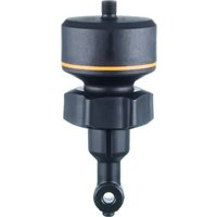
LDL400 - Industrial sensor IFM - Free user manual and instructions
Find the device manual for free LDL400 IFM in PDF.


User questions about LDL400 IFM
0 question about this device. Answer the ones you know or ask your own.
Ask a new question about this device
Download the instructions for your Industrial sensor in PDF format for free! Find your manual LDL400 - IFM and take your electronic device back in hand. On this page are published all the documents necessary for the use of your device. LDL400 by IFM.
USER MANUAL LDL400 IFM
Operating instructions
Inductive conductivity sensor G1½ all-plastic
device
LDL400
Contents
1 Preliminary note.... 3
1.1 Symbols used.... 3
1.2 Warnings.... 3
2 Safety instructions 4
2.1 Cybersecurity 4
3 Transport, handling and storage 5
4 Intended use 6
4.1 Application area 6
4.2 Restriction of the application area.... 6
5 Function 7
5.1 Measuring principle 7
5.2 Analogue function 7
5.3 Defined state in case of a fault 8
5.4 IO-Link 8
6 Installation.... 9
6.1 Installation location / environment 9
6.2 Installation procedure.... 10
6.3 Mounting the adapter in pipes 10
6.4 Mounting the device in the adapter.... 10
7 Electrical connection 11
7.1 For the cULus scope of validity 11
7.2 Maritime Type approval (IACS MR scheme) restriction 11
8 Parameter setting 12
8.1 Adjustable parameters and system commands.... 12
8.1.1 General parameters 12
8.1.2 More settings 13
8.1.3 Example parameter setting.... 14
8.2 Temperature influence and temperature coefficient 14
8.2.1 Influence of the medium on the temperature.... 14
8.3 Determination of the temperature coefficient tempco 14
9 Operation.... 16
9.1 Function check.... 16
9.2 Operating and diagnostic messages via IO-Link 16
9.3 Output response in different operating states 16
10 Maintenance, repair and disposal 17
11 Factory setting.... 18
1 Preliminary note
You will find instructions, technical data, approvals and further information using the QR code on the unit / packaging or at documentation.ifm.com.
1.1 Symbols used
Requirement
Instruction
Reaction, result
bold Designation of keys, buttons or indications
→ Cross-reference without link
→ Cross-reference with link


1.2 Warnings
Warnings indicate the possibility of personal injury and damage to property. This enables safe product handling. Warnings are graded as follows:

WARNING
Warning of serious personal injury
▷ If the warning is not observed, fatal and serious injuries are possible.

CAUTION
Warning of minor to moderate personal injury
▷ If the warning is not observed, minor to moderate injuries are possible.

ATTENTION
Warning of damage to property
▷ If the warning is not observed, damage to property is possible.
2 Safety instructions
- The unit described is a subcomponent for integration into a system.
- The system architect is responsible for the safety of the system.
-
The system architect undertakes to perform a risk assessment and to create documentation in accordance with legal and normative requirements to be provided to the operator and user of the system. This documentation must contain all necessary information and safety instructions for the operator, the user and, if applicable, for any service personnel authorised by the architect of the system.
-
Read this document before setting up the product and keep it during the entire service life.
- The product must be suitable for the corresponding applications and environmental conditions without any restrictions.
- Only use the product for its intended purpose (→ Intended use).
- If the operating instructions or the technical data are not adhered to, personal injury and/or damage to property may occur.
- The manufacturer assumes no liability or warranty for any consequences caused by tampering with the product or incorrect use by the operator.
- Installation, electrical connection, set-up, operation and maintenance of the product must be carried out by qualified personnel authorised by the machine operator.
- Protect units and cables against damage.
- Only use the product for permissible media (→ Technical data).
- The unit complies with the standard EN 61000-6-4 and is a class A product. The unit may cause radio interference in domestic areas. If interference occurs, the user must take appropriate actions.
2.1 Cybersecurity
Installation
The device is suitable for operation in a secure environment according to IEC 62443-1-1.
The device was designed for operation behind a firewall.
▶ Carry out a risk assessment of the system according to IEC 62443-1-1.
▶ Take measures to ensure physical security.
Operation
▶ Observe the security functions described in the product documentation and the recommendations for their use.
Maintenance
▶ Back up system configuration and system data in accordance with your company's change management processes.
Decommissioning
▶ Ensure that no sensitive information can fall into unauthorised hands.
▶ Always reset the system settings to the factory settings before decommissioning the device.
3 Transport, handling and storage
▶ Store the device in its original packaging.
▶ When the device is to be stored again, use the original packaging.
▶ Otherwise, provide unused connections with either a mating connector or a protective cap and pack the device in suitable packaging.
▶ Observe the permissible ambient conditions for the device during storage (→ Technical data).
▶ In case of return shipment, ensure that the unit is free from soiling, especially from dangerous and toxic substances.
4 Intended use
The device detects the conductivity and the temperature of liquids in pipes.
The device also determines the salt concentration for NaCl solutions (common salt solutions). Application area ➕ 6, Restriction of the application area ➕ 6
The device is designed for direct contact with the medium.
4.1 Application area
• Water and waste water industry
• Desalination plants (seawater environment, low temperatures)
- Salt water / seawater applications
• Air conditioning systems and cooling tower monitoring (desalination control)
- Rinsing baths
• Concentration monitoring
• Determining the concentration of NaCl solutions (common salt solutions)

The device calculates the concentration (mass fraction of NaCl in water) from the measured conductivity value. The value determined is only valid for NaCl solutions in pure and ultrapure water and only to a limited extent for NaCl solutions in water with higher conductivity. Further information and notes on determining the concentration ➕ Technical data sheet.
4.2 Restriction of the application area
- Use the device only for media to which the wetted materials are sufficiently resistant (→ Technical data sheet).
- Only use the device in temperature ranges for which it is sufficiently suitable (→ Technical data sheet).
- The device is not suitable for liquids with a low electrical conductivity (e.g. oils, greases, highly purified water).
- The device is not suitable for applications where the probe is subjected to permanent and high mechanical stress (e.g. abrasive media or fast flowing media containing solid particles).
• Not suited for media prone to formation of deposit. - Determining the concentration of NaCl solutions is only suitable for NaCl solutions in water. Application area → 6
- The determined concentration value is only available via the IO-Link communication interface with acyclical data request. IO-Link → 8
5 Function
5.1 Measuring principle

The unit operates on the inductive measuring principle. It measures the electrical conductivity of the medium to be monitored by means of an induced current flow in a measuring channel through which the medium flows.
To compensate the influence of the temperature, the process temperature is detected by a temperature probe in the sensor tip.
5.2 Analogue function
The unit provides an analogue signal proportional to the conductivity or (as option) the temperature. The analogue output (OUT2) can be configured.
Curve of the analogue signal (factory setting):

Curve of the analogue signal (measuring range scaled):

L: conductivity:
T: temperature
1: [ou2] = [l]
2: [ou2] = [InEG]
ASP2: analogue start point
AEP2: analogue end point
5.3 Defined state in case of a fault
If a fault is detected or if the signal quality is below a minimum value, the output OUT2 passes into a defined state according to Namur recommendation (NE43).
For this case, the response of the output can be set via the parameter [FOU2].
5.4 IO-Link
IO-Link is a communication system for connecting intelligent sensors and actuators to automation systems. IO-Link is standardised in the IEC 61131-9 standard.

General information on IO-Link at io-link.ifm

Input Output Device Description (IODD) with all parameters, process data and detailed descriptions of the device at documentation.ifm.com
IO-Link offers the following advantages:
• Interference-free transmission of all data and process values
• Parameter setting in the running process or presetting outside the application
- Parameters for identifying the connected devices in the system
• Additional parameters and diagnostic functions
• Automatic backup and restore of parameter sets in case of device replacement (data storage)
- Logging of parameter sets, process values and events
• Device description file (IODD - Input Output Device Description) for easy project planning
• Standardised electrical connection
- Remote maintenance
6 Installation

Before installing and removing the device:
▶ Make sure that no pressure is applied to the system and there is no medium in the pipe or tank.

The sensor is supplied without installation / connection accessories.

Only use accessories from ifm electronic gmbh! The optimum function is not ensured when using components from other manufacturers.

Available accessories: www.ifm.com.
6.1 Installation location / environment

A correct fit and function of the unit and ingress resistance of the connection are only ensured using ifm adapters.

When process connections from other manufacturers are used:
▶ Ensure mechanical compatibility, function and tightness.
▶ To avoid malfunctions and damage to the sensor and plant, adhere to a distance of at least 5 mm from the sensor tip to neighbouring objects (e.g. pipe and container walls, structures).

Orientation of the measurement channel:
▶ The measuring channel must be correctly aligned. Observe the marking on the sensor housing. When using ifm adapters, correct alignment is ensured thanks to mechanical coding. Mounting the device in the adapter 10
▷ This ensures correct flow through the measuring channel.

1: measurement channel

▶ Installation preferably before or in rising pipes.
▶ Provide for inlet and outlet pipe lengths (2) (minimum 3 x DN, optimum 5 x DN).
▷ Disturbances caused by bends, valves or pipe reductions, etc. are then eliminated.

S: Interference
DN: Pipe diameter
1: Sensor
2: Inlet and outlet pipe lengths
6.2 Installation procedure
The device is installed using a T-adapter (→ Accessories).
6.3 Mounting the adapter in pipes

Install the adapter using standard procedures and the recognised rules of technology.
▶ Remove the protective packaging only just before mounting.
▶ Ensure cleanliness of the sealing areas.
▶ If the sealing surfaces are damaged, replace the device or the adapter.
6.4 Mounting the device in the adapter

Only use adapters from the ifm accessories.
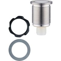
▶ Place the O-ring in the groove on the T-adapter.
▶ Insert the device into the T-adapter and position it so that the groove on the device fits over the guide pin on the wall.
▷ This ensures the correct installation position and correct flow through the measuring channel.
▶ Screw the coupling nut onto the thread of the T-adapter and tighten hand-tight.
▶ After installation, check the entire system for ingress resistance.
7 Electrical connection

The unit must be connected by a qualified electrician.
Observe the national and international regulations for the installation of electrical equipment.
Voltage supply according to SELV, PELV.
▶ Disconnect power.
▶ Connect the unit as follows:


| Pin | Core colour | |
| 1: | BN | Brown |
| 2: | WH | White |
| 3: | BU | Blue |
| 4: | BK | Black |
| OUT1: IO-Link | ||
| OUT2: Analogue output | ||
| Colours to DIN EN 60947-5-2 | ||

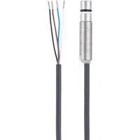
The connection accessories are not supplied with the device.
Available accessories: www.ifm.com
7.1 For the cULus scope of validity
The electrical supply must only be made via SELV/PELV circuits.
A class 2 power supply can also be used and is not excluded.
The device must be supplied via a limited energy circuit according to section 9.4 of UL standard 61010-1, 3rd issue, or equivalent.
The external circuits connected to the device must be SELV/PELV circuits.
The device is designed to be safe at least under the following conditions:
- Indoor use
• Altitude up to 2000 m
• Relative air humidity up to max. 90 %, non condensing - Pollution degree 3
- Use UL-certified approved cables of category PVVA or CYJV with data suitable for the application.
- No special treatment is needed for cleaning the device. (This note does not apply to hygienic applications).
7.2 Maritime Type approval (IACS MR scheme) restriction
The operating voltage of the sensor must be well protected against surges caused by lightning, for example by operating with SELV/PELV power supplies.
8 Parameter setting
The parameters are set via the IO-Link interface.

Depending on the parameter setting, the parameters available in the menu may change.
Parameters can be set before installation or during operation.

If you change parameters during operation, this will influence the function of the plant.
▶ Ensure that there will be no malfunctions in your plant.
During parameter setting the unit remains in the operating mode. It continues to monitor with the existing parameter until the parameter setting has been completed.
The device parameters can be set via the IO-Link interface in the following ways, for example:
- Parameter setting via a suitable parameter setting software, e.g. ifm moneo|configure
• Parameter setting via a PLC
• Parameter setting via an IIoT application
Requirements for parameter setting via the IO-Link interface:
√ The Input Output Device Description (IODD) for the device in case of parameter setting via a parameter setting software, see documentation.ifm.com
√ The IO-Link interface description (PDF) for the device in case of parameter setting via a PLC or IIoT application, see documentation.ifm.com
√ An IO-Link master
▶ Connect the IO-Link master to the parameter setting software, the PLC or the IIoT application.
▶ Connect the device to a suitable free port of the IO-Link master.
▶ Set the port of the IO-Link master to the IO-Link operating mode.
▷ The device changes to the IO-Link mode.
▶ Change the parameter settings in the software.
▶ Write the parameter settings to the device.

Support for system integration and parameter setting via IO-Link:
→ Manual of the parameter setting software (e.g. moneo)
Explanations and startup packages at ifm.com/cnt/io-link-system-integration.
8.1 Adjustable parameters and system commands
8.1.1 General parameters
| Reset the application (system command) | The parameters of the technology-specific application are set to default values. The identification parameters remain unchanged. If activated in the port configuration of the master, an upload will be carried out to the data memory of the master. | |
| Back-to-Box (system command) | The device parameters are set to the factory default values and communication is blocked until the next time the device is switched on and off. Note: Disconnect the device directly from the master port! | |
| uni. C | Selection of the unit for conductivity displayed in the parameter setting tool [S/m] - conductivity is displayed in S/m [μS/cm] - conductivity is displayed in μS/cm. | |
| CGA-COND | Calibration gain (cell constant correction factor). With this factor the sensor can be calibrated to a present system, or to a system optimised to a certain conductivity value. Setting range: 80...120 %Reference values: | |
| Installation in | Correction factor [CGA] | |
| DN32 | 102 % | |
| DN40 | 100 % | |
| T. Cmp-COND | Temperature compensation. The conductivity is determined according to the standard temperature ([rEF. T]) when the temperature coefficient (medium-specific characteristic value) is entered. Setting range: 0...5 % | |
| rEF. T-COND | Standard temperature (25 °C) = reference temperature for measuring the conductivity. The standard temperature can be adjusted by the user, if necessary. Setting range: 15...35 °C | |
| Offset TEMP | Zero-point calibration (calibration offset) / temperature. Setting range: +/- 5 K. | |
| Concentration | Display of the mass fraction of NaCl in water, calculated from the current conductivity measured value. Intended use ➕ 6 | |
8.1.2 More settings
| ou2 | Output configuration for the analogue output (OUT2): [I] = measuring range is provided as 4...20 mA [InEG] = measuring range is provided as 20...4 mA [OFF] = output OFF (high impedance) |
| SEL2 | Assignment of the analogue output to the process value: [COND] = conductivity [TEMP] = temperature |
| FOU2 | Response of OUT2 in case of a fault: [OU] = analogue output reacts according to process value, if possible. Otherwise: analogue output goes to [OFF]. [On] = analogue output switches to value > 21 mA in case of a fault [OFF] = analogue output switches to value < 3.6 mA in case of a fault |
| ASP2-COND | Analogue start point conductivity; setting range: 0...1000000 μS/cm. Distance to AEP2-COND: ASP2-COND must not be higher than 50 % AEP2-COND. |
| AEP2-COND | Analogue end point conductivity; setting range: 500...2000000 μS/cm. Distance to ASP2-COND: AEP2-COND must be at least two times ASP2-COND. |
| ASP2-TEMP | Analogue start point temperature; setting range: -25...70 °C. Distance to AEP2-TEMP: min. 30 °C |
| AEP2-TEMP | Analogue end point temperature; setting range: 10...100 °C. Distance to ASP2-TEMP: min. 30 °C |
| Lo. COND | Minimum value memory for conductivity |
| Hi. COND | Maximum value memory for conductivity |
| Reset [Hi. COND] and [Lo. COND] memory | Reset maximum and minimum value memory (button to activate the system command). |
| Lo. TEMP | Minimum value memory for the temperature |
| Hi. TEMP | Maximum value memory for the temperature |
| Reset [Hi. TEMP] and [Lo. TEMP] memory | Reset maximum and minimum value memory (button to activate the system command) |
| dAP-COND | Damping of the measured signal, setting range: 0...20 s |
| S. Tim | Simulation; entering the simulation time, setting range: 1...60 min |
| S. COND | Simulation; selection of the conductivity value to be simulated, setting range: 0...2000000 μS/cm |
| S. TEMP | Simulation; selection of the temperature value to be simulated, setting range: -25...150 °C |
| S. On | Simulation; status of the simulation:[OFF] = simulation OFF[On] = simulation ON |
| Start simulation | Start simulation (button to activate the system command) |
| Stop simulation | Stop simulation (button to activate the system command) |
For further information and parameter description, especially about SSC-related parameters, please refer to the IODD description (www.ifm.com) or to the context-specific parameter descriptions of the used parameter setting software.
8.1.3 Example parameter setting
▶ Set the temperature compensation (parameter [T. Cmp-COND]) to a medium with the temperature coefficient 3.0 %/K. Example: [T. Cmp-COND] = [3,0].
▶ Make all other settings.
▶ Transfer the sensor data to the device.
8.2 Temperature influence and temperature coefficient
8.2.1 Influence of the medium on the temperature
The conductivity depends on the temperature. When the temperature increases, the conductivity changes. This temperature influence depends on the respective medium and can be compensated by the unit if the temperature coefficient (tempco) of the medium is known. The temperature compensation is set via the parameter [T. Cmp-COND]. Then the temperature-compensated conductivity value corresponds to the conductivity at standard temperature (25 °C; factory setting of the parameter [rEF. T-COND]).

For medium that is not changed the same tempco value has to be set for all sensors (unit-independent characteristic value). There is no further dependence on the measuring principle, the lot or the manufacturer of the sensors.

If the temperature coefficient of the medium is not known, it can be determined. See: Determination of the temperature coefficient tempco

In an IO-Link environment, existing tempcos of the media can be stored as recipe in the controller so that the accuracy of the values to be detected is improved.
8.3 Determination of the temperature coefficient tempco
- Set the parameters [T. Cmp-COND] and [dAP-COND] to zero: [T. Cmp-COND] = [0], [dAP-COND] = [0].
▶ Write the changed values to the sensor.
- Adjust the medium to 25° C, for example, and take down the value of the conductivity after 2 min.
- Heat up the medium to 45° C, for example, and take down the value of the conductivity after 2 min.
Example of values taken down:
medium at 25° C = 500 µ S/cm; medium at 45° C = 800 µ S/cm temperature change = 20 K
- Calculate the change of the conductivity in percent.
The conductivity has increased by 300 µ S/cm.
The percentage change is 300/500 = 60 %. - Calculate the temperature coefficient tempco: The tempco is calculated from the change in percent and the temperature change: Tk = 60 % / 20 K = 3 % / K
- The calculated tempco can now be adopted into the parameter [T. Cmp-COND].
Example: [T. Cmp-COND] = [3]. If necessary, set the damping (parameter [dAP-COND]) again.
▶ Write values to the sensor.
9 Operation
9.1 Function check
After power-on the device is in the operating mode. It carries out its measurement and evaluation functions and generates process data (via IO-Link) according to the set parameters.
▶ Check whether the unit operates correctly.
9.2 Operating and diagnostic messages via IO-Link
IODD and IODD descriptive text as a PDF file at: www.ifm.com
9.3 Output response in different operating states
| OUT1 *) | OUT2 | |
| Initialisation | process value invalid | OFF |
| Normal operation | process value according to conductivity / temperature | according to conductivity / temperature and setting [ou2] |
| Fault | process value invalid | < 3.6 mA at [FOU2] = [OFF] > 21 mA at [FOU2] = [On] no change at [FOU2] = [OU] |
*) process value via IO-Link
10 Maintenance, repair and disposal
▶ Avoid the formation of deposits and soiling at the sensor element.
▶ To avoid damage to the sensor, no hard or sharp objects must be used when cleaning the sensor manually.
It is not possible to repair the device.
▶ After use, dispose of the unit in an environmentally friendly way in accordance with the applicable national regulations.

When the medium is changed, it may also be necessary to adapt the device settings for a higher accuracy (parameter [T. Cmp-COND]).
11 Factory setting
| Factory setting | User settings | |
| uni. C | μS/cm | |
| CGA-COND | 100 (%) | |
| T. Cmp-COND | 2 (%) | |
| rEF. T-COND | 25 (°C) | |
| Offset TEMP | 0 (K) | |
| ou2 | I | |
| SEL2 | COND (conductivity) | |
| FOU2 | OFF | |
| ASP2-COND | 0 (μS/cm) | |
| AEP2-COND | 2000000 (μS/cm) | |
| ASP2-TEMP | -5 (°C) | |
| AEP2-TEMP | 80 (°C) | |
| Lo. COND | --- | |
| Hi. COND | --- | |
| Lo. TEMP | --- | |
| Hi. TEMP | --- | |
| dAP-COND | 1 (s) | |
| S. Tim | 3 min | |
| S. COND | 500 (μS/cm) | |
| S. TEMP | 20 (°C) | |
| S. On | OFF |

- 1 PRELIMINARY NOTE
- 1.1 SYMBOLS USED
- 1.2 WARNINGS
- 2 SAFETY INSTRUCTIONS
- 2.1 CYBERSECURITY
- 3 TRANSPORT, HANDLING AND STORAGE
- 4 INTENDED USE
- 4.1 APPLICATION AREA
- 4.2 RESTRICTION OF THE APPLICATION AREA
- 5 FUNCTION
- 5.1 MEASURING PRINCIPLE
- 5.2 ANALOGUE FUNCTION
- 5.3 DEFINED STATE IN CASE OF A FAULT
- 5.4 IO-LINK
- 6 INSTALLATION
- 6.1 INSTALLATION LOCATION / ENVIRONMENT
- 6.2 INSTALLATION PROCEDURE
- 6.3 MOUNTING THE ADAPTER IN PIPES
- 6.4 MOUNTING THE DEVICE IN THE ADAPTER
- 7 ELECTRICAL CONNECTION
- 7.1 FOR THE CULUS SCOPE OF VALIDITY
- 7.2 MARITIME TYPE APPROVAL (IACS MR SCHEME) RESTRICTION
- 8 PARAMETER SETTING
- 8.1 ADJUSTABLE PARAMETERS AND SYSTEM COMMANDS
- 8.1.1 GENERAL PARAMETERS
- 8.1.2 MORE SETTINGS
- 8.1.3 EXAMPLE PARAMETER SETTING
- 8.2 TEMPERATURE INFLUENCE AND TEMPERATURE COEFFICIENT
- 8.2.1 INFLUENCE OF THE MEDIUM ON THE TEMPERATURE
- 8.3 DETERMINATION OF THE TEMPERATURE COEFFICIENT TEMPCO
- 9 OPERATION
- 9.1 FUNCTION CHECK
- 9.2 OPERATING AND DIAGNOSTIC MESSAGES VIA IO-LINK
- 9.3 OUTPUT RESPONSE IN DIFFERENT OPERATING STATES
- 10 MAINTENANCE, REPAIR AND DISPOSAL
- 11 FACTORY SETTING
Brand : IFM
Model : LDL400
Category : Industrial sensor