
PG9936 - Smoke detector DSC - Free user manual and instructions
Find the device manual for free PG9936 DSC in PDF.

| Product Type | Wireless Smoke and Heat Detector |
| Brand | DSC |
| Model | PG9936 |
| Detection Technology | Photoelectric (smoke) and thermovelocimetric (heat) |
| Diameter | 125 mm |
| Height | 63 mm |
| Weight (with batteries) | 243 g |
| Power Supply | 3 AAA batteries (Duracell Procell PC2400 or Energizer E92) |
| Battery life after low battery indication | 14 days |
| Alarm sound level | ≥ 85 dBA (ANSI Temporal 3 pattern) |
| Recommended spacing | 21.3 m |
| Operating temperature (smoke detector) | 4.4 °C to 37.8 °C |
| Operating humidity | 15% to 90% RH (non-condensing) |
| Regulatory compliance | UL268, ULC-S531, FCC Part 15, ISED Canada |
| Warranty | 12 months |
| Recommended service life | 10 years |
| Alarm silence | Yes, with automatic reset |
| Tamper protection | Yes |
| Supervision transmission frequency | Every 64 minutes |
| Maintenance and cleaning | Vacuum dust, clean with damp soft cloth, do not paint |
Frequently Asked Questions - PG9936 DSC
User questions about PG9936 DSC
0 question about this device. Answer the ones you know or ask your own.
Ask a new question about this device
Download the instructions for your Smoke detector in PDF format for free! Find your manual PG9936 - DSC and take your electronic device back in hand. On this page are published all the documents necessary for the use of your device. PG9936 by DSC.
USER MANUAL PG9936 DSC
ENG PG9936/PG8936/PG4936 Series Wireless Smoke and Heat Detector
Installation and Operating Instructions
Read this instruction sheet thoroughly before installation and use of the PG9936/PG8936/PG4936
Introduction
The PG9936/PG8936/PG4936 is a wireless photoelectric smoke and heat detect temperature and rate of rise heat detector, and an internal piezoelectric alarm. The following versions are available:
| Frequency (MHz) Version Region | ||||
| 915 | PG9936 | North America | ||
| 868 | PG8936 | Europe | ||
| 433 | PG4936 | Europe/International and Australia | ||
Compatible Devices
This smoke detector is compatible with UL/ULC Listed DSC Wireless Control Wireless Receivers using PowerG Technology, PowerSeries Neo and iotega pla
NOTE: For UL/ULC installations use this device only conjunction with compatible DSC wireless
receivers: HS2128, HS2064, HS2032, HS2016
control units when connected to HSM2HOST9
wireless receiver, HS2LCDRF(P)9, HS2ICNRF(P)9
Keypads with integrated receiver, PG9920
repeater and Wireless Alarm Systems WS900- and WS900-29. Transmissions occur at
approximately 915 MHz (912 MHz to 919 MH
Operation
Approximately every 7 to 8 seconds the unit tests for a smoke or heat alarm this sequence the unit also performs self diagnostics, and checks for tampers; normal operation the green LED flashes every 60 seconds and the sounder dc
Smoke Alarm
The smoke detector alarms when the signal level exceeds the "alarm" threshold matically restores when the signal level falls below the alarm "restore" threshold. alarm the red LED flashes once per second and the sounder sounds the eva pattern.
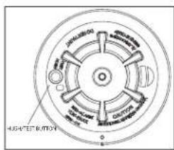
Alarm Silencing
This smoke alarm is provided with an automatically resettable alarm silencing fee sensor is in alarm, press the Test/Silence/Reset button to silence the local and alarm and transmit an alarm restore event to the control panel. The red LED second for up to 7 minutes, to indicate the alarm has been silenced.
After an alarm the red LED will flash once every 4 seconds to indicate an alarm silence feature has a fixed time setting that desensitizes the smoke alarm. Alarm is silencing does not disable the smoke alarm but rather reduces its smoke falling 3. the silenced period the smoke alarm restores automatically to its intended smoke around the unit is dense enough to suggest a potentially dangerous situation in alarm, or may return to the alarm state quickly.
Detector Trouble
When the detector has a general fault, the yellow LED blinks once every four there is a chirp every 48 seconds. After 4 hours, the panel will display a
Detector and Status Indication
| Status LEDs | Sounder | |
| Normal Green | flash every 60 seconds Off | |
| Heat Alarm | Red flash every 1 second ANSI | S3.41 temporal 3 |
| Heat Test | Red flash every 1 second ANSI | S3.41 temporal 3 |
| Smoke Alarm | Red flash every 1 second | ANSI S3.41 temporal 3(press button to hush for 5-minutes) |
| Smoke Test(with canned smoke) | Red flash every 1 second | ANSI S3.41 temporal 3(press button to hush for 5-minutes) |
| Test Alarm(button press) | Red flash every 1 second ANSI | S3.41 temporal 3 |
| Detector Trouble | Yellow flash every 4 seconds | One chirp every 48 seconds |
| Low Battery | Yellow flash every 12 seconds | One chirp every 48 seconds(press button to hush for 12 |
| Detector Dirty | Yellow flash every 8 seconds | One chirp every 48 seconds |
| Power-up Red | yellow, green, flash sequence | One chirp at the end of th up sequence |
| Tamper | Red, yellow, green flash sequence every 12 seconds | Off |
| Hush Mode | Red flash every 1 second (alarm) | Off hush) |
| Yellow flash every 12 seconds (low battery hush) | Off | |
Detector Cleaning Required
When the detector is contaminated, the yellow LED blinks once every 8 seconds and there is a chirp every 48 seconds. Refer to the MAINTENANCE section for cleaning the detector. After 4 hours, the panel displays a message fire clean.
Heat Alarm
The heat detector (cULus versions only) alarms when the heat signal level exceeds the heat alarm threshold (135 °F / 58 °C); and will automatically restore when the heat signal level falls below the heat alarm threshold (restore). The detector also goes into a heat alarm state when there is a rapid increase in the temperature over a short period of time. During an alarm the LED flashes 1/second and the sounder sounds the evacuation temporal pattern.
Tamper
^1 The removal of the detector from the mounting plate initiates a "tamper" transmission. The tamper condition is restored after the detector is mounted on the plate.
Wireless Transmissions
A supervisory message is transmitted at 128 second intervals for the PGx936. If the signal is not received the control panel determines that the detector is missing. The detector transmits the following:
- Alarm / Alarm Restore - (heat or smoke alarm). Transmitted at time of 1 NOTE: During an alarm condition, the detector sends an alarm event to the control panel. When the condition is restored, the detector sends an alarm restore event to the panel and sets the alarm restore indicator. The red LED blinks once every 4 seconds until the Alarm in memory is cleared. You can clear the alarm from the control panel, or press and hold the test button for
- Tamper / Tamper Restore - (tamper switch activated) 10 second maximum before transmission.
- Low Battery - (battery voltage falls below threshold). Battery voltage is tested & transmitted at the time of a supervisory or other transmissions.
- Trouble - (detector fault or sensor compensation limit reached). Troubles are transmitted at the time of occurrence (one trouble per supervisory interval).
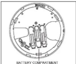
Batteries
The wireless smoke heat alarm is powered by 3 AAA Duracell Procell PC2400 or 3 AAA Energizer E92 batteries (included). The detector regularly checks for a low battery. If a low battery is detected, the transmitter sends a low battery message to the control panel, which displays the detector's ID at low battery. In addition, the yellow LED of the detector blinks every 12 seconds. The detector's sounder chirps every 48 seconds and the yellow LED continues to blink until the batteries are replaced. Pressing the hush button silences the chirps for 12 hours, if no other trouble conditions exist. The batteries should be replaced with new batteries when the chirps begin.
At low battery, the test button is disabled. An alternative test method is gas such as 'Solo A10 smoke detector tester'. Shake the can well, aim and spray a short burst (no more than 1 sec) at the detector. If the repeat every 10 seconds until alarm sounds or for a maximum of 1 m NOTE: If the alarm does not sound, contact the installer or dealer for
Battery Installation and Replacement
CAUTION: Risk of explosion if battery is replaced by an incorrect type. tery according to the manufacturer's instructions.
To replace batteries, complete the following steps:
- Remove the detector from its mounting base by twisting the detector Carefully remove batteries by lifting from the "+" end using a flathead pose of them according to local regulations.
- To ensure a proper power-down sequence, wait a minimum of 30 sec installing new batteries.
- Install 3 new AAA batteries, available from a local Duracell or Energiz- tery compartment. Install the batteries by inserting the "-" end first, the end down. If the batteries are incorrectly inserted, please remove them them out from the "+" end and correctly re-inserting them.
- Re-install the detector on its mounting base by turning the detector ing marks align.
- After the power-up sequence, the green LED should blink once every rate normal operation. If the batteries are not installed correctly, the cate and the batteries may be damaged. If the detector does not po batteries are installed correctly and fully charged.
- Test the detector as described later.
toCONSTANT EXPOSURES TO HIGH OR LOW TEMPERATURES OR HIGH HUMID it REDUCHE BATTERYdetted.
alarm does not sound. Installation Instructions
The PGx936 Series wireless smoke detector shall be installed and used within that provides the pollution degree max 2 and over voltages category II in Norway, indoor only. The equipment is designed to be installed by SERVICE PE (DISPOSE PERSON) bat-defined as a person having the appropriate technical triaience necessary to be aware of hazards to which that person may be exposed task and of measures to minimize the risks to that person or other persons).
counterclockwise. Smoke Detector Placement
screwdriver and dis-
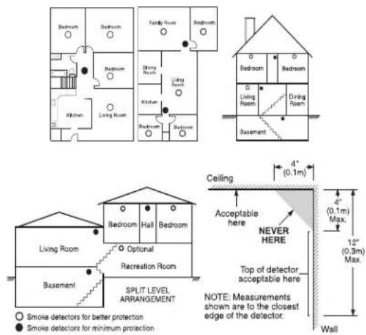
Research has shown that all hostile fires in homes generate smoke to a great
Experiments with typical fires in homes indicate that detectable quantities of smc
detectable levels of heat in most cases. For these reasons, smoke alarms show
outside level of each sleeping area and on each storey of the home.
The following the information is for general guidance only and it is recommended to be corrected by the codes and regulations be consulted when locating and installing smoke alarms. I carefully by listing. Mended that additional smoke alarms beyond those required for minimum protection installed. Additional areas that should be protected include: the basement; bedroom where smokers sleep; dining rooms; furnace and utility rooms; and any hallways by the required units. On smooth ceilings, detectors may be spaced 9.1 m (3 guide. Other spacing may be required depending on ceiling height, air movement of joists, uninsulated ceilings, etc. Consult National Fire Alarm Code NFPA 72, or other appropriate national standards for installation recommendations.
- Do not locate smoke detectors at the top of peaked or gabled ceilings; the in these locations may prevent the unit from detecting smoke.
- Avoid areas with turbulent air flow, such as near doors, fans or windows. ment around the detector may prevent smoke from entering the unit.
- Do not locate detectors in areas of high humidity.
lockwise not until the detectors in areas where the temperature rises above 38 °C (100 °F) or falls below 5 °C (41 °F).
60 SmetrendsetectorIndemust always be installed in USA in accordance with Chapter tector72, wilthenoNatopar Fire Alarm Code: 29.5.1.1.
Where, referred they applicable laws, codes, or standards for a specific type of approved single and multiple-station smoke alarms shall be installed as follows:
-
In all sleeping rooms and guest rooms.
-
Outside of each separate dwelling unit sleeping area, within 6.4 m sleeping room, the distance measured along a path of travel.
-
On every level of a dwelling unit, including basements.
-
On every level of a residential board and care occupancy (small ments and excluding crawl spaces and unfinished attics.
-
In the living areas of a guest suite.
-
In the living areas of a residential board and care occupancy (small NOTE: In Australia the device shall not be installed in locations where temperature is lower than 5 °C or higher than 45 °C.
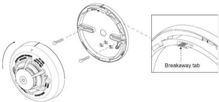
2. Mount Smoke Detector Backplate
NOTE: of The alarm device should only be installed by a competent engineer or Smoke detectors are not to be used with smoke detector guards unless
has been evaluated and found suitable for that purpose.
Once a suitable location is found, mount the detector backplate. Install the mount the ceiling or on the wall (if local ordinances permit) using screw locations as two screws and anchors provided. Maneuver the base so the screws are at 1
taculty). screws, slots and secure.
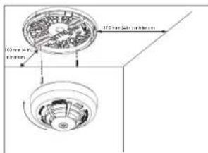
3. Mounting
Fit the detector inside the base by aligning it over the base. The detector's should be slightly offset from the mounting base tamper release tab. Then turn clockwise until it clicks into place.
If there is a need to activate the built-in anti-tamper lock, carefully remove th the backplace as shown in the following figure.
4. Device Enrollment
The 7-digit serial number located on the back of the smoke detector housing must be inalled faults that could prevent a smoke or heat alarm
on the alarm systems control panel. See the Receiver Installation Manual ment procedure. For placement tests remove the detector from its backplate (tamper) and then reattach. Wait at least 30 seconds for the test result
A general description of the procedure is provided in the following flow c
Step Procedure
1 See the Installation Manual for the alarm system that the device is ensure that the proper steps are used.
2 Enter the Device Enrollment option through the specified method and appropriate option to add the new device.
3 Enroll the device by inserting the batteries to power up the device ID. For example, ID No. 202-XXXX.
NOTE: When enrolling the PGx936 detector to DSC control panels (see Devices), the detector will be enrolled as a Smoke and Heat xxxx, and labeled Smoke and Heat in the panel.
4 Select the desired Zone Number.
5 Configure any device parameters that are required. Enter the DEV SETTINGS menu and select the required options to configure the detector:
6 Mount and test the detector. See Smoke Detector Unit Test for information device. In addition, see the alarm systems Installation Manual that the device on for other test procedures that are required.
5. Test Unit
NOTE: The central monitoring station if used, should be notified prior to the operated. This prevents a false alarm and an unnecessary response from theitoring station.
Initiate test by pressing the test button for 5 seconds minimum. Alarm activatio the flashing red LED, the sounder, and transmission of the alarm signal to th The detector restores to normal when the test button is released.
NOTE: Allow a minimum of 20 seconds after power up and after test, alarm activations.
NOTE: If the detector is in one of the following states when a test is initiated; it will not enter an alarm state:
Compensation Trouble
ng musthe be ineralled faults that could prevent a smoke or heat alarm
Owner's Instructions for one second
Fire a Safety again. The Home
Most fires occur in the home, and to minimize this danger, it is recommended. Fire safety audit be conducted and a family escape plan be developed.
Household Fire Safety Audit
- Are all electrical appliances and outlets in safe condition? Check for frayed loaded lighting circuits, etc. If you are uncertain about the condition of ycances or household service, have a professional evaluation.
- Are all flammable liquids safely stored in closed containers, and in a coc and entered the device cleaning the unit with flammable liquids should be avoided.
- Are hazardous materials for example, matches out of the reach of children. Compatible furnaces and wood burning appliances properly installed, clean, and in etectoorded? 201-in doubt, have a professional evaluation.
Family Escape Planning
There is often very little time between the detection of a fire and the time. Because of this, it is very important that a family escape plan be developed
• Every family member should participate in the escape plan.
- Study the possible escape routes from each location within the house. occur at night, special attention should be given to the escape routes ters.
- It is essential that escape from a bedroom be possible without opening. Consider the following when making your escape plans:
- Ensure that doors and windows that open to the outside are easily open they are not painted shut and that the locking mechanisms operate sm
- If opening or using the exit is too difficult for children, the elderly or handicapped, plans for their rescue should be developed. This plan includes making sure that form the rescue can promptly hear the fire warning signal.
- If the exit is above the ground level, an approved fire ladder or rope should be provided, as well as training in its use.
- Exits on the ground level should be kept clear. Be sure to remove snow from exterior patio doors in the winter and that outdoor furniture or equipment does not
- The family should have a predetermined assembly point where everyone for; for example, across the street or at a neighbor's house.
- Once everyone is out of the house, call the Fire Department.
- A good plan emphasizes a quick escape. Do not investigate first or attempt to fight the fire, and do not attempt to rescue belongings or valuables as this takes up do not re-enter the house; wait for the Fire Department.
- Write the plan down and rehearse it frequently so that should an emerge everyone will know what to do. Revise the plan as conditions change; there are more or fewer family members in the home or if there are
• Make sure your fire warning system is operational by conducting weekly unsure about system operation, contact your smoke detector installer or
- It is recommended that you contact your local Fire Department and requation on home fire safety and escape planning. If available, have your officer conduct an in-house fire safety inspection.
Testing Your Smoke Detector
Follow the test procedure described here or contact your smoke detector for testing instructions. It is recommended to test the entire alarm system week to verify the operation of all system functions.
Smoke Detector Unit Test
Initiate test by pressing the test button for 5 seconds, the sounder makes this time. Press the button until the unit alarm sounds, an alarm should panel. When the button is released, the alarm should cease. If this does not interact me, it's correct type, in good condition and are installed correctly. upon sleeping into the functional testing of the smoke detector, check the unit's to ensure proper operation. To test the sensing chamber, use an aerosol test the 0 minute smoke detector tester'. Shake the can well, aim it at the smoke detector burst (no more than 1 second) at the detector. If the alarm does not sound end. Ensure that alarm sounds or for a maximum of 1 minute. If the smoke de ploy properly, call your smoke detector installer or dealer for service.
Smoke Detector Test those who are to per-
Before you test, complete the following steps:
-
Insert the battery and then mount the detector on the bracket before cor smoke detector test.
-
After the battery is inserted, wait 2 minutes before testing it. The detectable block Diagnostic Test Mode for 15 minutes.
can 3. belt discount recommended to perform the Periodic Test and use either the Instal Diagnostic Mode) or the User code (User Diagnostic Mode) to test.
CAUTION: The diagnostic test cannot be performed when the tamper is open. Press and hold the test button for 2 seconds. When the button is released, up sequence Once evesite, occur, the Red LED lights for 0.5 s > off for 0.5 s.
This is followed by 2 loud alarm beeps and at the same time the red LED gehey detectorarists smoke, heat, and battery functions.
for the amphotectors in diagnostic mode, the detector performs the diagnostic test be hanges to the house.
tests. If you are Sensitivity Indicating Means
test the detector is indicating 'Detector Dirty' with a Yellow LED flash every 8 hourly fire prevention and a fire clean message on the panel, the detector's compensation feature is no longer able to compensate for dust and dirt accum no longer be within the marked sensitivity. If the detector is indicating 'Normal' flash every 60 seconds it is within the marked sensitivity range.
or NOPE if the pane displays the fire clean message after cleaning, call the installer or dealer for item at least once a
Diagnostic Test
The following sequence of events occur during a diagnostic test:
cAirpinThe noisectoduring performs a link quality test.
e se Noteto The detector must be in local or diagnostic mode to perform the In diagnostic mode, if you press the test button for more than 6 seconds
message is sent to the panel and a Temporal-3 alarm signal is sounded. Spabing thrating: 70 ft (21.3 m)
sequence is completed, the panel responds by sending an "Alarm in Memory Sensitivity (threshold) PG9936 (cULus): 1.26 - 2.39 %/ foot obscurati
to the device.
B. At the end of the diagnostic test the LED blinks three times. The the received signal strength.
| LEDResponse | Green LEDblinks | Orange LEDblinks | Red LEDblinks | No blinks |
| Reception | Strong Good | Poor | Paired, nocommunicaton |
IMPORTANT! Reliable reception must be confirmed. Therefore, "poor" signal strength is not acceptable. If you receive a "poor" signal from the device, re-locate it and or "strong" signal strength is received. For UL/CUL installations, the test results must be "strong". See the alarm systems installation guide for detailed diagnostic tests.
Owner's Maintenance
The smoke detector is designed to require minimum maintenance. If the vacuum with a small brush attachment. If the case is greasy, wipe the cloth slightly dampened with soapy water.
Never disassemble the smoke detector; there are no user serviceable pa You may only remove detector from backplate to replace batteries if n installer. When replacing the batteries, follow the instructions specified in Instructions.
Never paint the unit. Paint may prevent smoke from entering the unit. renovations or repainting, take precautions to avoid dust, paint or chem to the detector.
If the unit is located in an area where it is exposed to high levels of false alarms, it may require service; contact your smoke detector installer or Testing and maintenance procedures shall be in accordance with CAN/ULC-S5
Specifications
• Regulatory Listings: UL268/ULC-S531 PG9936
• Diameter: 5 in (125 mm)
• Height: 2.5 in (63 mm)
• Weight (including battery): 8.75 oz (243 g)
• Color: White
- Alarm Sensitivity (threshold) PG4936 / PG8936: complies with EN14604 following Audible Signalate(ANSI Temporal 3): 85 dBA minimum in alarm
- Operating Temperature: PG9936 40 °F - 100 °F (4.4 °C - 37.8 °C)
- Operating Temperature with Heat Detector: 32 °F - 100 °F (0 °C - 37.
- Operating Temperature for Smoke Alarm:PG4936 41 °F - 113 °F (5 °C
Photoelectric Smoke Alarm (Australia)
• Heat Alarm: 135 °F (57 °C);
• Humidity: 15 % - 90 % RH, non-condensing
• Approved Batteries: 3 AAA Energizer E92 or Duracell Procell PC2400
• Alarm Silencing: PG4936 8 minutes automatically resettable
• Supervisory Transmission Frequency: PG9936 64 minute intervals
re-test until a "good" Supervisory Transmission Frequency: PG4936 / PG8936 12 minute intervals
• Maximum Tx Power: 433.22 MHz - 434.64 MHz: 10 mW, 868.0 MHz - 868.7 MHz - 869.2 MHz: 14 mW.
• Low Battery Detection: Low battery 14 days remaining
caseLimited Warranty
catal gently Cowith warrants for a period of twelve months from the date of purchase, the product shall be free of defects in materials and workmanship under normal use and that in fulfilment of any breach of such warranty. Digital Security Controls shall at its option, repair or replace the defective equipment once return of the equipment to its repair depot. This
parts inside the unit of repair, and is shot, repair or replace the defective equipment upon return of the equipment to its repair depot. This warranty applies only to defects in parts and workmanship and not to damage incurred in shipping or due due to defect by the control of Digital Security Controls such as lightning, excessive voltage, mechanical shock water not serviced by
damage, or damage arising out of abuse, alteration or improper application of the equipment.
The foregoing warranty shall apply only to the original buyer, and is and shall be in line of any and all other warranties, whether expressed or implied and of all other obligations or liabilities on the part of Digital Security Controls. Digital Security (f) not by the assumption liability nor authorizes any other person purporting to act on its behalf to modify or to change this warranty nor to assume for it any other warranty or liability concerning this product. All information rights reserved.
- In the event shall Digital Security Controls be liable for any direct, indirect or consequential damages, loss of anticipated profits, loss of time or any other losses incurred by the buyer in connection with the purchase, installation, or operation or failure of
less of time of any other issues imained by the Bayer in connection with the purchase, installation of operation of failure of this product, insects and causes
Smoke Detectors: Smoke detectors that are a part of this system may not properly alert occupants of a fire for a number of or reasons; some of which follow. The smoke detectors may have been improperly installed or positioned. Str 552 and to reach the smoke detectors, such as when the fire is in a chimney, walls or roofs, or on the other side of closed doors.
Smoke detectors may not detect smoke from fires on another level of the residence or building. Every fire is different in the amount of smoke produced and the rate of burning. Smoke detectors cannot sense all types of fires equally well. Smoke detectors may not provide timely warning of fires caused by carelessness or safety hazards such as smoking in bed, violent explosions, escaping gas, improper storage of flammable materials, overloaded electrical circuits, children playing with matches or arson.
Even if the smoke detector operates as intended, there may be circumstances when there is insufficient warning to allow all occupants to escape in time to avoid injury or death.
Warning: Digital Security Controls recommends that the entire system be completely tested on a regular basis. However, despite frequent testing, and due to, but not limited to, criminal tampering or electrical disruption, it is possible for this product to fail to perform as expected.
Important Information: Changes or modifications not expressly approved by Digital Security Controls could void the user's authority to operate this equipment.
EULA
IMPORTANT - READ CAREFULLY: DSC Software purchased with or without Products and Component righted and is purchased under the following license terms:
This End-User License Agreement ("EULA") is a legal agreement between You (the company, individual acquired the Software and any related Hardware) and Digital Security Controls, a division of Tyco Sa Ltd. ("DSC"), the manufacturer of the integrated security systems and the developer of the software products or components ("HARDWARE") which You acquired. If the DSC software product ("SOFTWARE" "SOFTWARE") is intended to be accompanied by HARDWARE, and is NOT accompanied by new HAR use, copy or install the SOFTWARE PRODUCT. The SOFTWARE PRODUCT includes computer software, associated media, printed materials, and "online" or electronic documentation. Any software provided along SOFTWARE PRODUCT that is associated with a separate end-user license agreement is licensed to Y that license agreement. By installing, copying, downloading, storing, accessing or otherwise using the SOFTWARE PRODUCT. You agree unconditionally to be bound by the terms of this EULA, even if this EULA is fixation of any previous arrangement or contract. If You do not agree to the terms of this EULA, DSC is unwilling to license the SOFTWARE PRODUCT to You, and You have no right to use it.
SOFTWARE PRODUCT LICENSE
The SOFTWARE PRODUCT is protected by copyright laws and international copyright treaties, as well property laws and treaties. The SOFTWARE PRODUCT is licensed, not sold.
GRANT OF LICENSE This EULA grants You the following rights
Software Installation and Use - For each license You acquire, You may have only one copy of the SOFTWARE PRODUCT installed
Storage/Network Use - The SOFTWARE PRODUCT may not be installed, accessed, displayed, run, shared or used concurrently on or from different computers, inducing a workstation, terminal or other digital electronic device ("Device"). In other words, if You have several workstations, You will have to acquire a license for each workstation where the SOFTWARE will be used.
Backup Copy - You may make backup copies of the SOFTWARE PRODUCT, but You may only have one copy per license installed at any given time. You may use the back-up copy solely for archival purposes. Except as expressly provided in this EULA, You may not otherwise make copies of the SOFTWARE PRODUCT, including the printed ma SOFTWARE.
DESCRIPTION OF OTHER RIGHTS AND LIMITATIONS
Limitations on Reverse Engineering, Decompilation and Disassembly - You may not reverse engineer, decomple, or disassemble the SOFTWARE PRODUCT, except and only to the extent that such activity is expressly law notwithstanding this limitation. You may not make any changes or modifications to the Software, without the written permission of an officer of DSC. You may not remove any proprietary notices, marks or labels from shall institute reasonable measures to ensure compliance with the terms and conditions of this EULA. Separation of Components - The SOFTWARE PRODUCT is licensed as a single product. Its component parts may not be separated for use on more than one HARDWARE unit.
Single INTEGRATED PRODUCT - If You acquired this SOFTWARE with HARDWARE, then the SOFTWARE PRODUCT is licensed with the HARDWARE as a single integrated product. In this case, the SOFTWARE PRODUCT the HARDWARE as set forth in this EULA.
Rental - You may not rent, lease or lend the SOFTWARE PRODUCT. You may not make it available to others or post it on a server or web site.
Software Product Transfer - You may transfer all of Your rights under this EULA only as part of a permanent sale or transfer of the HARDWARE, provided You retain no copies. You transfer all of the SOFTWARE PRODUCT component parts, the media and printed materials, any upgrades and this EULA), and provided the recipient terms of this EULA. If the SOFTWARE PRODUCT is an upgrade, any transfer must also include all prior SOFTWARE PRODUCT.
Termination - Without prejudice to any other rights, DSC may terminate this EULA. You fail to comply with the terms and conditions of this EULA. In such event, You must destroy all copies of the SOFTWARE PRODUCT and parts.
Trademarks - This EULA does not grant You any rights in connection with any trademarks or service marks of DSC or its sup-ntnersis copy-
COPYRIGHT - AI title and intellectual property rights in and to the SOFTWARE PRODUCT (including but not limited to any intellectual photographs, and text incorporated into the SOFTWARE PRODUCT), the accompanying printed materials of Products, Cabeen, and Software Products are owned by DSC or its suppliers. You may not copy the print name and related SOFTWARE PRODUCT. All titles and intellectual property rights in and to the content which I Product Use of the SOFTWARE PRODUCT are the property of the respective content owner and may be done by other intellectual property laws and treaties. This EULA grants You no rights to use such content. All rights and experts included under this EULA are reserved by DSC and its suppliers.
EXPORT RESTRICTIONS - You agree that You will not export or re-export the SOFTWARE PRODUCT to any country, person under entity termsect of to Canadian export restrictions.
FCHOICE OF LAW - This Software License Agreement is governed by the laws of the Province of Ontario, Canada. ARBITRATION - Disputtering in connection with this Agreement shall be determined by final and binding arbitration in accordance with the Arbitration Act, and the parties agree to be bound by the arbitrator's decision. The place of arbitration shall be Toronto, Canada, and the language of the arbitration shall be English.
LIMITED WARRANTY
NO WARRANICTUAL DSC PROVIDES THE SOFTWARE "AS IS" WITHOUT WARRANTY. DSC DOES NOT W THE SOFTWARE WILL MEET YOUR REQUIREMENTS OR THAT OPERATION OF THE SOFTWARE WILL I UNINTERRUPTED OR ERROR-FREE.
CHANGES IN OPERATING ENVIRONMENT - DSC shall not be responsible for problems caused by changes in the operating characteristics of the HARDWARE, or for problems in the interaction of the SOFTWARE PRODUCT, SOFTWARE or HARDWARE PRODUCTS.
LIMITATION OF LIABILITY; WARRANTY REFLECTS ALLOCATION OF RISK - IN ANY EVENT, IF ANY S IMPLIES WARRANTIES OR CONDITIONS NOT STATED IN THIS LICENSE AGREEMENT, DSC'S ENTIRE LM ANY PROVISION OF THIS LICENSE AGREEMENT SHALL BE LIMITED TO THE GREATER OF THE AMC PAID BY YOU TO LICENSE THE SOFTWARE PRODUCT AND FIVE CANADIAN DOLLARS (CAD\$5.00). BEJ JURISDICTIONS DO NOT ALLOW THE EXCLUSION OR LIMITATION OF LIABILITY FOR CONSEQUENTIAL INCIDENTIAL DAMAGES. THE ABOVE LIMITATION MAY NOT APPLY TO YOU.
DISCLAIMER OF WARRANTIES - THIS WARRANTY CONTAINS THE ENTIRE WARRANTY AND SHALL BE ANY AND ALL OTHER WARRANTIES, WHETHER EXPRESSED OR IMPLIED (INCLUDING ALL IMPLIED WAIT MERCHANTABILITY OR FITNESS FOR A PARTICULAR PURPOSE) AND OF ALL OTHER OBLIGATIONS OR THE PARTY OPPIED DSC MAKES NO OTHER WARRANTIES. DSC NEITHER ASSUMES NOR AUTHORIZE PERSON PURPORTING TO ACT ON ITS BEHALF TO MODIFY OR TO CHANGE THIS WARRANTY, NOR THE SOFTWARE WARRANTY OR LIABILITY CONCERNING THIS SOFTWARE PRODUCT.
EXCLUSIVE REMEDY AND LIMITATION OF WARRANTY - UNDER NO CIRCUMSTANCES SHALL DSC BE ANY SPECIAL, INCIDENTAL, CONSEQUENTIAL OR INDIRECT DAMAGES BASED UPON BREACH OF WARRA BREACH OF CONTRACT, NEGLIGENCE, STRICT LIABILITY, OR ANY OTHER LEGAL THEORY, SUCH DAM. INCLUDE, BUT ARE NOT LIMITED TO, LOSS OF PROFITS, LOSS OF THE SOFTWARE PRODUCT OR EQUIPMENT, COST OF WITH CAPITAL, COST OF SUBSTITUTE OR REPLACEMENT EQUIPMENT, FACILITIES OR DOWN TIME, PURCHASERS TIME, THE CLAIMS OF THIRD PARTIES, INCLUDING CUSTOMERS, AND INJU PROPERTY.
(including all
DSC recommends that the entire system be completely tested on a regular basis. However, despite frequent testing, and due to, but not limited to, criminal tampering or electrical disruption, it is possible for this SOFTWARE PRODUCT to fail to per-
form as expected.
Regulatory Information
The smoke alarm PG9936/PG8936/PG4936 has a recommended service life of 10 years under normal conditions of use.
Please refer to the label applied to the device indicating the recommended replacement year. For servicing the unit or replace-
ment batteries please call your installation company that provided you with the alarm system. NOTE: In Australia, the device shall not be installed in locations where the normal ambient temperature is lower than 41°F.
(5°C) or higher than 113°F (45°C).
This manual shall be used in conjunction with the Installation Manual of the alarm control panel. All the instructions specified
within that manual must be observed.
FCC and ISED Canada Compliance Statement
This device complies with FCC Rules Part 15 and with ISED Canada licence-exempt RSS standard(s). Operation is subject to
the following two conditions: (1) this device may not cause interference, and (2) this device must accept any interference,
including interference that may cause undesired operation of the device.
This Class B digital apparatus complies with Canadian ICES-003.
WARNING! To comply with FCC and IC RF exposure compliance requirements the device should be located at a distance of
at least 20 cm from all persons during normal operation. The antennas used for this product must not be co-located or oper-
ated in conjunction with any other antenna or transmitter.
Simplified EU declaration of conformity
Hereby, Tyco Safety Products Canada Ltd. declares that the radio equipment type is in compliance with Directive
2014/53/EU. The full text of the EU declaration of conformity is available at the following internet address:
PG4936: http://dsc.com/pdf/1709001 PG8936: http://dsc.com/pdf/1709003
Frequency band Maximum power
433.04 MHz - 434.79 MHz 10 mW
868.0 MHz - 868.6 MHz 14 mW
868.7 MHz - 869.2 MHz 14 mW
European single point of contact: Tyco Safety Products, Voltaweg 20, 6101 XK Echt, Netherlands.
Notified Body BSI (2797) 604, 2005/AC:2008
DSC, Toronto, Canada
2019
2797-CPR-713760
Smoke Alarm Device

© 2019 Johnson Controls. All rights reserved. JOHNSON CONTROLS, TYCO and DSC are trademarks and/or registered
trademarks. Unauthorized use is strictly prohibited
Tech Support: 1-800-387-3630 (Canada & U.S.)
or 905-760-3000 • www.dsc.com
This Class B digital apparatus complies with Canadian ICES-003.

- ENG PG9936/PG8936/PG4936 Series Wireless Smoke and Heat Detector
- Introduction
- Compatible Devices
- Operation
- Smoke Alarm
- Alarm Silencing
- Detector Trouble
- Detector Cleaning Required
- Heat Alarm
- Tamper
- Wireless Transmissions
- Batteries
- Battery Installation and Replacement
- alarm does not sound. Installation Instructions
- counterclockwise. Smoke Detector Placement
- Mount Smoke Detector Backplate
- Mounting
- Device Enrollment
- Step Procedure
- Test Unit
- Owner's Instructions for one second
- Fire a Safety again. The Home
- Household Fire Safety Audit
- Family Escape Planning
- Testing Your Smoke Detector
- Smoke Detector Unit Test
- Smoke Detector Test those who are to per-
- tests. If you are Sensitivity Indicating Means
- Diagnostic Test
- Owner's Maintenance
- Specifications
- caseLimited Warranty
- EULA
- SOFTWARE PRODUCT LICENSE
- LIMITED WARRANTY
- Regulatory Information
- FCC and ISED Canada Compliance Statement
- Simplified EU declaration of conformity
Brand : DSC
Model : PG9936
Category : Smoke detector