PTK5507 - Alarm system DSC - Free user manual and instructions
Find the device manual for free PTK5507 DSC in PDF.


| Product Type | Wireless Keypad for DSC Alarm System |
| Model | PTK5507 |
| Brand | DSC |
| Display | Backlit LCD with icons |
| Keypad | Backlit numeric keys with dedicated function buttons |
| Communication | 2-way voice via built-in speaker and microphone |
| Wireless Protocol | Encrypted 2.4 GHz or 433 MHz (depending on version) |
| Panic Buttons | Yes (fire, medical, police) |
| Tamper Protection | Wall tamper switch |
| Power Source | 4x AA alkaline batteries (optional AC adapter) |
| Battery Life | Approximately 2 years with normal use |
| Low Battery Indicator | Yes, audible and visual |
| Dimensions (HxWxD) | 165 x 114 x 30 mm (6.5 x 4.5 x 1.2 in) |
| Weight (with batteries) | Approximately 250 g (0.55 lbs) |
| Operating Temperature | 0°C to 49°C (32°F to 120°F) |
| Compatible Panels | DSC PowerSeries Neo (PC1832, PC1864, etc.) |
| Maximum Distance from Panel | Up to 100 m (300 ft) in open air |
| Maintenance | Clean with a soft, dry cloth. Do not use liquids or solvents. |
| Security | AES-128 encryption for wireless communication |
| Spare Parts & Repairability | Replacement batteries available; no user-serviceable parts inside. Contact DSC for repairs. |
Frequently Asked Questions - PTK5507 DSC
User questions about PTK5507 DSC
0 question about this device. Answer the ones you know or ask your own.
Ask a new question about this device
Download the instructions for your Alarm system in PDF format for free! Find your manual PTK5507 - DSC and take your electronic device back in hand. On this page are published all the documents necessary for the use of your device. PTK5507 by DSC.
USER MANUAL PTK5507 DSC
PTK5507v1.0Touchscreen UserManual
WARNING: This manual contains information on limitations regarding product use, function and information on the limitation as to liability of the manufacturer. The entire manual should be carefully read.
TableofContents
Welcome Screen 2
Emergency Key 2
Arming and Disarming the System 3
Stay Arm (Arming the Perimeter) 3
Silent Exit Delay.... 3
Disarm....5
Away Arm. 5
Bell/Siren Sounds After Away Arming 5
Remote Arming and Disarming 5
When Alarm Sounds 5
Intrusion (Burglary) Alarm Continuous Siren 6
Fire Alarm Pulsed Siren 6
Wireless Carbon Monoxide Alarm 6
Additional Options 6
Photos 6
Quick Exit 6
Time & Date Programming 6
Keypad Mode 6
Door Chime (Chime enable/disable) 6
Zone Status 7
Bypassed Zones. 9
Bypassing Zones with a PTK5507 9
Troubles.... 10
Alarm Memory 11
Sensor Reset 11
Outputs 12
Options 12
Access Codes. 13
User Code Attributes 13
Inherent Attributes (all codes except installer and maintenance) ..... 13
Programmable Attributes 13
Bell Squawk Attribute 13
Partition Assignment Mask.... 13
Erasing an Access Code 14
Installer Menu 14
User Functions.... 14
Keypad Configuration 15
Chime Enabled/Disabled. 16
Arming.... 16
Partition Status 17
PK5500/RFK5500/RFK5564/PTK5507 Global Status Screen. . . . . . . 17
Keypad Mode 17
Reference Sheets 18
System Information.... 18
Access Codes 19
Sensor/Zone Information 20
Testing Your System 21
Testing Your Keypad Sounder and Siren 21
Testing Your Entire System 21
Walk Test Mode 21
Allowing Computer Access To Your System. 21
AlwaysensureyouobtainthelatestversionoftheUserGuide.UpdatedversionsofthisUserGuideareavailablebycontactingyourdistributor.
NOTE: Use these instructions in conjunction with the Installation Manual of the alarm panel with which this equipment is intended to be used.
WARNING: Read and save these instructions! Follow all warnings and instructions specified within this document and/or on the equipment.
IMPORTANT SAFETY INSTRUCTIONS
Toreducetheriskoffire, electricshockand/orinjury, observethefollowing:
- Donotspillanytypeofliquidontheequipment.
- Donotattempttoservicethisproductyourself.Openingorremovingthecovermayexposeyoutodangerousvoltageorotherrisk.Referservicingtoqualifiedservicepersonnel.Neveropenthedeviceyourself.
- Donottouchtheequipmentanditsconnectedcablesduringanelectricalstorm;theremaybeariskofelectric shock.
- DonotusetheAlarmSystemtoreportagasleakifthesystemisnearaleak.
REGULARMAINTENANCEANDTROUBLESHOOTING
KeepyourPTK5507Touchscreenkeypadinoptimalconditionbyfollowingalltheinstructionsthatareincludedwithin thismanualand/ormarkedontheproduct.
HANDLINGPRECAUTIONS
Donotapplyexcessiveforcetothedisplaysurfaceortheadjoiningareassincethismaycausethecolortonetovary.
CLEANING
- If the displaysurface is contaminated, breathe on the surface and gently wipe it with as soft, dry cloth. If still not completely clean, moist cloth with isopropyl alcohol.
- Do not use abrasives, water, thinners, solvents or aerosol cleaners (spray polish), any aromatic solvents, ketones etc. that may enter through holes in the PTK5507 Touchscreen keypad and caused damage.
TROUBLESHOOTING
Occasionally, you may have a problem with your system. If this happens, your Alarm Controller will identify the problem and display an error message. Refer to the provided list when you see an error message on the display. If additional help is required, contact your distributor for service.
WARNING: This equipment, PTK5507 Touchscreen keypad shall be installed and used within an environment that provides the pollution degree max 2 and over-voltag categories, indoor only. It is designed to be installed, serviced and/or repaired by service persons only [service person is defined as a person having the appropriate technical training and experience necessary to be aware of hazard with which that person may be exposed in performing at task and of measurement to minimize risk to that person or other persons]. There are no parts replaceable by the end-user within this equipment
WARNING: Never obstruct the access to the Alarm controller to which this equipment is connected. These safety instructions should not prevent you from contacting the distributor and orthemanufacturerto obtain any further clarification and/or answerstoyourconcerns.
IMPORTANTNOTICE
A security system cannot prevent emergencies. It is only intended to alert you and, if included, your central station of an emergency situation. Security systems are very reliable but they may not work under all conditions, and they are not a substitute for prudent security practices or life and property insurance. Your security system should be installed and serviced by qualified security professionals who should instruct you on the level of protection that has been provided and on system operations.
Introduction
The PTK5507 Touchscreen is an interactive touch-sensitive color LCD that can be used on any Power-Series v4.2 and greater control panel. Due to the custom requirements of individual installations, some of the features described here may perform differently than described. Refer to your Installer's Instructions for the details of your specific installation and to the User Manual for general security system information.
Specifications/Features
- Display....7" TFT (800 × 480 pixel) Color Touchscreen
- Home button .... Home/Calibration/Reset
- LED indicators. 4 (Ready, Armed, Trouble, AC)
- Dimensions (mounting). 8.5" x 5.1" x 0.8" [127.9 mm (L) x 195 mm (W) x 20.35 mm (D)]
- Viewing angle .... Horizontal viewing angle: 70^ (typ.)
- Vertical viewing angle. 50° (top), 70° (bottom) (typ.)
- Brightness 280 cd/m ^2
- Operating environment ....-10°C to +55°C (14°F to 131°F)
- 5% to 93% relative humidity
- SD card slot holds any standard Secure Digital (SD) card* (32 x 24 x 2.1 mm) containing photos
- Display language(s).... English
*If necessary, the SD card can be formatted to file system FAT16 or 32 using a PC. The maximum size SD card supported is 32GB.
NOTE: For best results, photo resolution should be 800 x 480; please use photo-editing computer software to adjust your photos to the correct size. Photos larger than 1280 x 720 cannot be displayed by the Touchscreen.
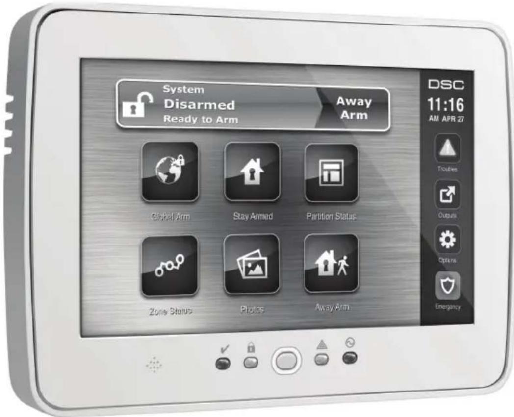
Welcome Screen
The date & time are displayed in the upper right corner of the screen.
The system status (i.e., Ready, Armed, Exit Delay etc.) is displayed at the top of the screen.
Figure 1 - Welcome Screen

Emergency Key
Figure 2 - Emergency Screen

When the emergency key is pressed, a new page will appear with:
Fire Fire Assistance Required. Press and hold for 2 seconds to activate.
Ambulance Medical or other Assistance Required. Press and hold for 2 seconds to activate.
Panic Police Assistance Required. Press and hold for 2 seconds to activate.
IMPORTANT NOTE: The Ambulance and Panic keys are ON by default. The Fire key will not function unless programmed by the Installer. Please ask your installer if the Fire, Ambulance and Panic keys are enabled.
NOTE: These events are recorded in the log.
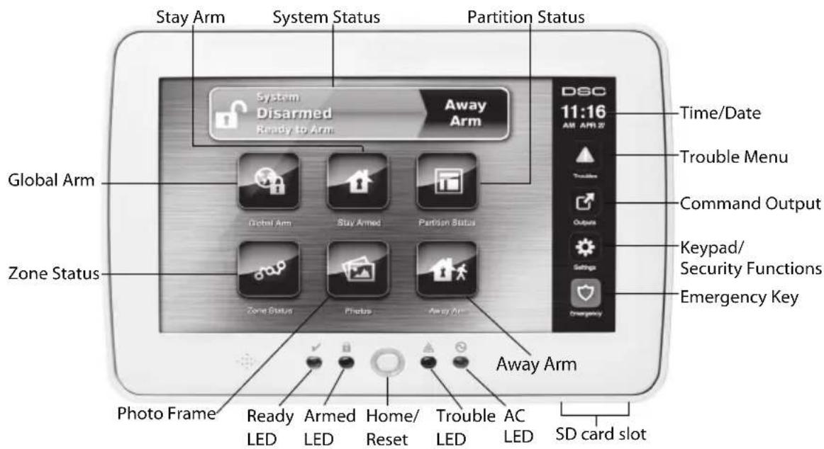
Figure 3 - Controls & Indicators
Arming and Disarming the System
Stay Arm (Arming the Perimeter)
Ask your alarm company if this function is available on your system.
Stay arming bypasses the interior protection (i.e., motion sensors) and arms the perimeter of the system (i.e., doors and windows). Close all sensors (i.e., stop motion and close doors). The Ready (√) indicator should be on. Press the Stay Arm button and/or enter your Access Code and do not leave the premises (if your installer has programmed this button). During exit delay, the Armed (💡) and Ready (√) indicators turn on to visually indicate that the system is arming.
When the exit delay expires, the Ready LED turns off, the Armed LED remains on and the keypad stops sounding to indicate that the alarm system is armed.
NOTE: For SIA FAR listed panels, the Stay Arming exit delay will be twice as long as the Away Arming exit delay.
Silent Exit Delay
If the system is armed using the Stay Arm button or using the "No Entry" Arming method ([*][9][access code]), the audible progress annunciation (keypad buzzer) is silenced and the exit time doubled for that exit period only (CP-01 versions only).
NOTE: For non CP-01 versions, Standard exit time is used.
When Stay Arm is selected from the Home screen:
- The display indicates “Exit Delay in Progress,” and the pre-programmed exit delay begins.
• The Armed LED Indicator turns on.
NOTE: If Quick Arm is not enabled by the installer, then a numerical keypad is displayed (see Figure 4). Enter a valid access code to proceed.
Figure 4 - Keypad

If Disarm is selected during the exit delay, a numeric keypad is displayed.
- Enter (tap) your access code.
- The arming sequence is aborted and the system returns to the Home screen.
• The Armed LED turns OFF.
At the end of the pre-programmed exit delay:
• The Disarm screen is displayed.
• The Ready Indicator turns OFF.
- “Stay Armed-Bypass” is displayed in the Status Bar.
NOTE: This screen will go into stand-by mode after 15 minutes. Tap the screen to restore the display.
Disarm
If Disarm is selected:
• A numerical keypad is displayed.
- Enter your Access Code in the keypad.
- The system returns to the Home screen and the red Armed indicator turns OFF.
- The alarm status is momentarily displayed in the status bar, then "Ready" is displayed.
• The green Ready indicator turns ON.
Disarming Error
If your code is invalid, the system will not disarm and a 2-second error tone will sound. If this happens, press # and try again.
Away Arm
When Away Arm is selected:
- Enter a valid access code to proceed.
• The Armed LED Indicator turns ON. - "Exit Delay in Progress" is displayed in the Status Bar. The pre-programmed exit delay begins.
- The touchscreen "beeps" at a 1-second urgency interval during the exit delay. Then 3 beeps sound in the last 10 seconds.
NOTE: If Quick Arm is not enabled by the installer, a numerical keypad is displayed.
If Disarm is selected during the exit delay:
- A numeric keypad is displayed. Tap your access code.
- The Arming sequence is aborted and the system returns to the Home screen.
• The Armed LED turns OFF.
At the end of the pre-programmed exit delay:
• The Disarm screen is displayed.
• The Ready Indicator turns OFF.
- "Away Armed" is displayed in the Status Bar.
Bell/Siren Sounds After Away Arming
Audible Exit Fault
In an attempt to reduce false alarms, the Audible Exit Fault is designed to notify you of an improper exit when arming the system in the Away mode. In the event that you fail to exit the premises during the allotted exit delay period, or if you do not securely close the Exit/Entry door, the system will notify you that it was improperly armed in two ways: the keypad will emit one continuous beep and the bell or siren will sound.
Your installer will tell you if this feature has been enabled on your system. If this occurs:
- Re-enter the premises.
- Enter your access code to disarm the system. You must do this before the entry delay timer expires.
- Follow the Away arming procedure again, making sure to close the entry/exit door properly.
Arming Error
An error tone will sound if the system is unable to arm. This will happen if the system is not ready to arm (i.e., sensors are open), or if an incorrect user code has been entered. If this happens, ensure all sensors are secure. Press [#] and try again, ensuring that a valid access code is entered. Please check with your installer to determine if arming is inhibited by any other means.
Remote Arming and Disarming
The system can be armed and/or disarmed using the remote wireless key. When arming the system by using the Arm button on the wireless key, the system will acknowledge the command by sounding a single bell squawk (if bell squawk is enabled). When disarming using the Disarm button on the wireless key, the system will acknowledge the command by sounding two bell squawks (if bell squawk is enabled) that can be heard from the exterior of the premises.
When Alarm Sounds
The system can generate 4 different alarm sounds:
- Temporal/ pulsed siren = Fire Alarm
- 4 beeps, 5-second pause, 4 beeps = Carbon Monoxide Alarm
- Continuous siren = Intrusion (Burglary Alarm)
NOTE: The priority of signals is fire alarm, carbon monoxide alarm then burglary alarm.
Intrusion (Burglary) Alarm Continuous Siren
If you are unsure of the source of the alarm, approach with caution! If the alarm was accidental, enter your Access Code to silence the alarm. Call your central station to avoid a dispatch.
Fire Alarm Pulsed Siren

Follow your emergency evacuation plan immediately!
If the fire alarm was accidental (e.g., burned toast, bathroom steam, etc.), enter your Access Code to silence the alarm. Call your central station to avoid a dispatch. Ask your alarm company if your system has been equipped with fire detection. To reset the detectors, see the Sensor Reset section.
Wireless Carbon Monoxide Alarm
Activation of your CO alarm indicates the presence of carbon monoxide (CO), which can be fatal. During an alarm, the red LED on the CO detector flashes rapidly and the buzzer sounds with a repeating cadence of: 4 quick beeps, 5-second pause, 4 quick beeps. Also, during an alarm, the siren connected to the control panel produces a repeating cadence of 4 quick beeps, 5-second pause, 4 quick beeps. The keypad will also provide audible and visual indication of the CO alarm.
If an alarm sounds:
- Operate silence button.
- Call emergency services or your fire department.
- Immediately move outdoors or to an open door/window.
WARNING: Carefully review your Carbon Monoxide Installation/User Guide to determine the necessary actions required to ensure your safety and ensure that the equipment is operating correctly. Incorporate the steps outlined in the guide into your evacuation plan.
Additional Options
Photos
NOTE: For best results, photo resolution should be 800 x 480; please use photo-editing computer software to adjust your photos to the correct size. Photos larger than 1280 x 720 cannot be displayed by the Touchscreen.
When Photos is selected:
- The photos play automatically from the list of photos on your SD card.
- Tapping the screen once will bring you back to the home page.
Photo Settings
WARNING: Disassembling the keypad without first removing the SD card will cause damage to the unit.
Selecting Picture Frame from the Keypad Configuration menu will allow you to select the pictures for the slide show. You can also program the Transition Time between photos and the duration for the Photo Frame Timeout on this screen.
Quick Exit
If the system is armed and you need to exit, use the quick exit function to avoid disarming and rearming the system. To activate this function, tap the Quick Exit icon. You have 2 minutes to leave the premises through your exit door. When the door is closed again the remaining exit time is cancelled.
Time & Date Programming
Tap on Options. Select User Functions [Master Code] and then select Time & Date. Tap on the section you would like to change and use the up/down arrows to change time/date. Once done, press Save.
Keypad Mode
This option allows the PTK5507 Touchscreen to function as a traditional DSC keypad.
Door Chime (Chime enable/disable)
The keypad indicates the current state of the door chime function (Enabled or Disabled). To choose the opposite function, tap the 'Chime' icon. Three beeps indicate that the chime is ON (Enabled). One long beep indicates that chime is OFF (Disabled).
Zone Status
This screen allows you to view the status of the zones on the system.
Figure 5 - Zone Closed

Ready – the zone is closed. (See Figure 5 on page 7).
Open - the zone is open and needs to be closed. (See Figure 6 on page 7.)
Figure 6 - Zone Open

Trouble – the alarm panel has detected a technical problem with one or more components of the alarm system e.g., loss of AC power. (See Troubles on page 10.)
Fault - one or more of the zones on your system is not secure e.g., a window or door is open. (See Figure 7 on page 8.)
Figure 7 - Zone Fault

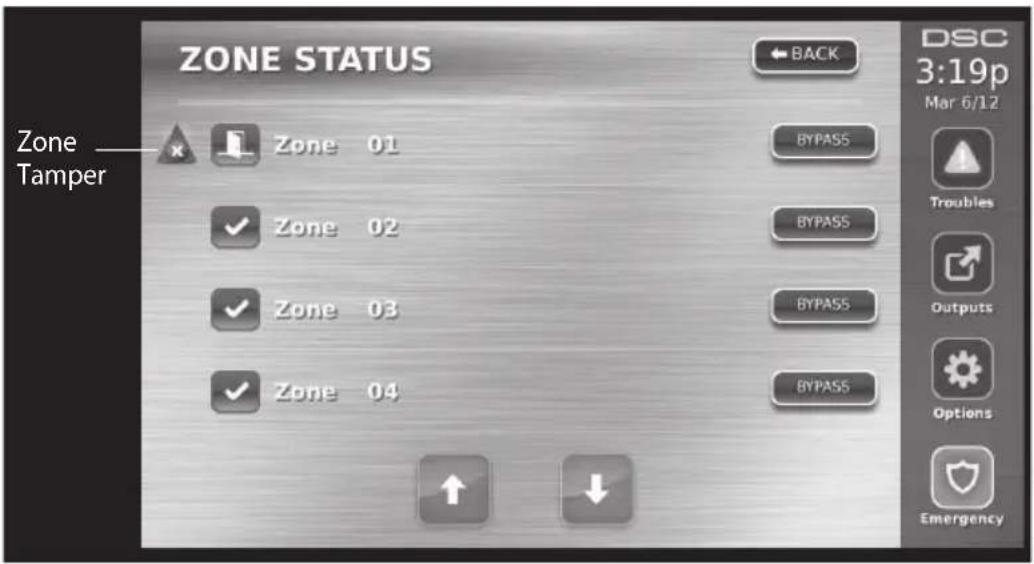
Tamper – the zone may have been compromised by an intruder. (See Figure 8 on page 8.)
Figure 8 - Zone Tamper
Low Battery - one or more modules in the zone has a low battery. (See Figure 9 on page 9.)
Figure 9 - Low Battery

Bypassed Zones
Use the zone bypass feature when a zone is open but the system needs to be armed. Bypassed zones will not cause an alarm when opened. Bypassing zones reduces the level of security. If you are bypassing a zone because it is not functioning, call a service technician immediately so that the problem can be resolved and your system returned to proper working order.
Ensure that no zones are unintentionally bypassed when arming your system. Zone bypassing can only be performed while the system is disarmed. Bypassed zones are automatically cancelled each time the system is disarmed and must be bypassed again, if required, before the next arming.
NOTE: 24-hour zones can only be unbypassed manually.
NOTE: For security reasons, your installer has programmed the system to prevent certain zones from being bypassed. (e.g., smoke detectors).
Bypassing Zones with a PTK5507
When in the Zone Status page, scroll up/down through the desired zones, and tap on the bypass icon to bypass the zone. To unbypass a zone, tap the unbypass icon.
Troubles
When a trouble condition is detected, the Trouble ( ) or System indicator will turn on, and the keypad will beep every 10 seconds. Press the ( ) key to silence the beeps. Press ( ) to view the trouble condition. The Trouble ( ) or System indicator will flash. The corresponding trouble will light up.
| TroublesCommentsAction | ||
| ServiceRequired (Pressformore details) | (1)LowBattery(2)BellCircuit(3)GeneralSystem Trouble (4)GeneralSystemTamper (5)GeneralSys-temSupervision(6)RFJamDetected(7)PC5204 LowBattery(8)PC5204ACLoss | Callforservice |
| ACLoss | Ifthebuildingand/orneighborhoodhaslostelec-tricalpower,thesystemwillcontinuetooperate onbatteryforseveralhours. | Callforservice |
| PhoneTrouble | Thesystemhasdetectedthatthetelephonelineis disconnected. | Callforservice |
| Communication Failure | Thesystemattemptedtocommunicatewiththe monitoringstation,butfailed.Thismaybedueto TelephoneLineFault. | Callforservice |
| ZoneFault | Thesystemisexperiencingdifficultieswithoneor moresensorsonthesystem.Presstodisplaythe zone. | Callforservice |
| ZoneTamper | Thesystemhasdetectedatamperconditionwith oneormoresensorsonthesystem.Presstodisplay thezone. | Callforservice |
| WirelessLowBat-tery | Thesystemhasdetectedalowbatterycondition withoneormoremodules/sensorsonthesystem. Presstodisplaythezone,keypad,wirelesskey(s) andRFDelinquencylowbatteryconditions.Press againtoseezonetroubles. | Callforservice |
| LossofClock | Ifcompletepowerwaslost(ACandBattery),the timeanddatewillneedtobereprogrammed. | ReprogramTime& Date |
Alarm Memory
When an alarm occurs, the Memory or System indicator will turn on.
To view which sensor(s) generated the alarm, press Alarms. The sensor number where the alarm occurred will be displayed (e.g. zone 3) (see Figure 10 on page 11).
Use the [<][>] scroll keys to view the sensors in alarm memory.
Press Back or Home to exit. To clear the memory, arm and disarm the system.
If an alarm sounded while armed, the keypad will automatically go to alarm memory when you disarm the system. In this instance, you should approach with caution, as the intruder may still be within the building/premises.
Figure 10 - Alarms in Memory

Sensor Reset
Certain sensors, after having detected an alarm condition, require a reset to exit the alarm condition (e.g., glass break sensors, smoke detectors, etc.). Ask your alarm company if this function is required on your system.
To reset the detectors, press the Reset (Command Output 2 if the installer did not program a label) button on the Outputs screen.
If a sensor fails to reset, it may still be detecting an alarm condition. If the sensor reset is successful, the alarm is cancelled. If unsuccessful, the alarm will reactivate or continue.
Outputs
Your installer may have programmed these keys to perform various functions (reset smoke detector after an alarm, open your garage door, etc.) To activate these functions, press Output and then press the appropriate option. See also Sensor Reset on page 11.
Figure 11 - Outputs

Options
From the Options menu on the right side of the Touchscreen (see Figure 12 on page 12), the following can be accessed:
- Access Codes
- Installer Menu
- User Functions
- Keypad Config
• Chime Enabled/Disabled - Arming
- Partition Status
- Keypad Mode
Figure 12 - Options

Access Codes
When Access Codes is selected from the Options menu, the keypad prompts for a Master Code. When a valid Master Code is entered, a numeric keypad is displayed with arrows to scroll to the desired user to add/edit. Press the select button to enter the user options.
Set Access Code - adds/edits the 4-digit code.
Set Partitions - assigns the user to partitions.
User Options – enables/disables different options for the user.
Delete User – deletes the user from the system.
The access codes have programmable attributes which allow zone bypassing, remote access using the ESCORT5580TC or one-time use activation.
Master Code (Access Code 40) - The master code, if programmed, can only be changed by the installer.
Supervisor Codes - These codes can be used to program additional codes which have equal or lesser attributes. Once programmed, the supervisor codes receive the master code's attributes. These attributes are changeable. Any user code can be made a supervisor code by enabling User Code Attribute 1 (please see below for details).
Duress Codes - Duress codes are standard user codes that transmit the Duress Reporting Code when entered to perform any function on the system. Any user code can be made a duress code by enabling User Code Attribute 2 (please see below for details).
NOTE: Duress codes are not valid when entering User Programming, Master Functions or Installer's sections.
NOTE: Access codes cannot be programmed as a duplicate or as a "Code +/- 1".
User Code Attributes
- The default attributes of a new code will be the attributes of the code used to enter User Programming whether it is a new code or an existing code being programmed.
- System Master Code 40 has partition access for all partitions, as well as attributes 3-4 ON by default.
NOTE: These attributes are not changeable.
Inherent Attributes (all codes except installer and maintenance)
Arm/Disarm - Any access code with partition access enabled will be valid for arming and disarming that partition.
Command Outputs (|*[7][1], [*[7][2], [*[7][3], and [*[7][4]) - If these outputs require access code entry, any Access Code with partition access will be valid for performing the command output functions on that partition.
Programmable Attributes
- SupervisorCode5. ForFutureUse
- DuressCode6. ForFutureUse
-
Zone Bypassing Enabled
-
BellSquawkuponArming/Disarming
4.ESCORTAccess8.OneTimeUseCode
Bell Squawk Attribute
This attribute is used to determine whether an access code should generate an arming/disarming Bell Squawk upon entry of the code for Away arming. The wireless keys with access codes associated with them may generate Arming/Disarming Bell squawks. If desired, this option may be used with codes that are manually entered. Please contact your installer to have this programmed.
NOTE: The Master Code cannot use the Bell Squawk attribute, but is required to enable it for other codes.
NOTE: This feature cannot prevent the Arming/Disarming squawks from being generated if an access code assigned to a wireless key is manually entered at a keypad.
Partition Assignment Mask
The master code has access to all partitions, and cannot be modified.
Partition Assignment Mask ([\*][5][Master/Supervisor Code][98][Code])
- Partition One Access (available for PC1616/PC1832/PC1864)
- Partition Two Access (available for PC1616/PC1832/PC1864)
- Partition Three Access (available for PC1832/PC1864)
- Partition Four Access (available for PC1832/PC1864)
- Partition Five Access (available for PC1864)
- Partition Six Access (available for PC1864)
- Partition Seven Access (available for PC1864)
- Partition Eight Access (available for PC1864)
Notes on Access Codes and Programming
- The master code's attributes cannot be changed.
- When a new code is programmed in User Programming it will be checked against all other codes in the system. If a duplicate code is found, an error tone is given and the code is returned to what it was before it was changed. This applies to both 4 and 6-digit codes.
Erasing an Access Code
To erase a code, select the code and choose Delete User. The system will delete the code immediately and the user will be returned to select another code.
Installer Menu
These functions are for the installer's use only.
User Functions
First disarm the system then enter Options, User Functions, then Master Code. This command is used to gain access to the following list of master functions of the system:
Time and Date
Enter desired time and date.
Auto-Arm Time
The system can be programmed to arm at a programmed time each day, per partition. Upon entry of this section, enter the desired Auto-Arm time for each day of the week.
At the selected Auto-Arm time, the keypad buzzers will sound for a programmed amount of time (programmable by the installer only) to warn that an auto-arm is in progress. The bell can also be programmed to squawk once every 10 seconds during this warning period. When the warning period is complete, the system will arm with no exit delay and in the Away Mode.
Auto-Arming can be cancelled or postponed by entering a valid access code only during the programmed warning period. Auto-Arming will be attempted at the same time the next day. When the Auto-Arming process is cancelled or postponed, the Auto-arm Cancellation Reporting Code will be transmitted (if programmed).
If arming is inhibited by one of the following, the Auto-Arm Cancellation transmission will be communicated:
• AC / DC Inhibit Arm
• Latching System Tampers
• Zone Expander Supervisory Fault
Enable DLS/Allow System Service
If enabled, the installer will be able to access Installer Programming via remote (DLS). In case of DLS access this provides a window where rings will be detected by the panel. The DLS window will remain open for 6 hrs, during which time the installer will be able to enter DLS an unlimited number of times. After the 6-hr window has expired, Installer's Programming will be unavailable again until the window is re-opened.
Event Buffer
Displays the date, time and the full description of the event.
The Log is organized from the most recent event (Top) to past events (Down).
The Left arrow scrolls forward in time.
The Right arrow scrolls back in time.
The Back returns you to the Home screen.
This screen will time out to the Home screen after 30 seconds of inactivity.
System Test
The system's Bell Output (2s), Keypad Lights and Communicator are tested. This test will also measure the panel's standby battery.
Auto-Arm/Disarm Control
Pressing Auto-Arm while in the User Function menu will enable (three beeps) or disable (one long beep) the Auto-Arm and Auto-Disarm feature, by partition. With this feature enabled, the panel will automatically arm in the Away mode (Stay/Away zones active) or disarm at the same time each day. The Auto-Arm time is programmed with the Auto-Arm time button. Auto-Disarm must be programmed by the system installer.
User Call-up
If enabled by the installer, the panel will make 1 attempt to call the downloading computer. The downloading computer must be waiting for the panel to call before downloading can be performed.
Keypad Configuration
Figure 13 - Keypad Configuration

Backlight – sets the brightness and screen timeout of the Touchscreen.
Buzzer Control – sets the buzzer volume of the Touchscreen.
Picture Frame – selects the pictures that will be displayed on the slideshow.
Calibration - calibrates the Touchscreen.
Clock Mode – displays the digital clock.
Clean Mode – allows the user to touch (i.e., clean) the screen without enabling or disabling any functions. The screen will remain in this mode for 30 seconds (See Figure 14 on page 16), then return to the Keypad Configuration screen (See Figure 13 on page 15).
Figure 14 - Clean Mode

Home Page – can be configured in one of two different views, Classic (square buttons) and Contemporary (rondel).
Language – allows the user to select different languages in which messages can be displayed.
Figure 15 - Language

Chime Enabled/Disabled
Door chime - To turn the door chime function On/Off, tap the Chime icon. There are 3 beeps to indicate that the chime is ON, 1 long beep to indicate the chime is OFF.
Arming
Stay Arm – arms the system in Stay mode.
Away Arm - arms the system in Away mode.
Night Arm – To fully arm the system when it has been armed in Stay Mode, press Night Arm button. All interior zones will now be armed except for devices programmed as Night Zones. Night zones are only armed in Away mode. This permits limited movement within the premises when the system is fully armed. Ensure that your installer has provided you with a list identifying zones programmed as night
zones. When the interior zones have been activated (i.e., Night Arm), you must enter your access code to disarm the system to gain access to interior areas that have not been programmed as night zones.
Quick Exit – see Quick Exit on page 6.
Global Away Arm – arms all partitions to which the User Code is assigned, in Away mode.
Global Stay Arm – arms all partitions to which the User Code is assigned, in Stay mode.
No Entry Arm – arms the system with no entry.
Partition Status
To view the partition status, press Options, User Functions, then Partition Status. The keypad shows basic status for up to 8 partitions, depending on the configuration of your system. Each partition is identified along with its current status.
PK5500/RFK5500/RFK5564/PTK5507 Global Status Screen
A keypad normally assigned to a partition can be temporarily assigned ("loaned") to Global mode, in order to program functions that affect the entire system and not just one partition. Figure 16 on page 17 is an example of a keypad loaned to Global mode.
Figure 16 - Partition Status

Keypad Mode
This option allows the PTK5507 Touchscreen to function as a traditional DSC keypad.
Reference Sheets
Fill out the following information for future reference and store this guide in a safe place.
System Information
Enabled?

[F] FIRE

[A] AUXILIARY

[P] PANIC

The Exit Delay Time is ____ seconds.

The Entry Delay Time is ____ seconds.
For Service
CentralStationInformation
Account#: Telephone#:
InstallerInformation:
Company: ____ Telephone#: ____
BatteryInstallation/ServiceDate:

If you suspect a false alarm signal has been sent to the central monitoring station, call the station to avoid an unnecessary response.
Access Codes
PC1616/PC1832/PC1864
MasterCode[40]:
| Code | Access Code | Code | Access Code | Code | Access Code | Code | Access Code |
| 01132542 | |||||||
| 021426 | |||||||
| 031527 | |||||||
| 041628 | |||||||
| 051729 | |||||||
| 061830 | |||||||
| 071931 | |||||||
| 082032 | |||||||
| 092133 | |||||||
| 102234 | |||||||
| 112340 | |||||||
| 122441 |
Sensor / Zone Information
| SensorProtectedAreaSensorTypeSensorProtectedAreaSensorType | |||||
| 0133 | |||||
| 0234 | |||||
| 0335 | |||||
| 0436 | |||||
| 0537 | |||||
| 0638 | |||||
| 0739 | |||||
| 0840 | |||||
| 0941 | |||||
| 1042 | |||||
| 1143 | |||||
| 1244 | |||||
| 1345 | |||||
| 1446 | |||||
| 1547 | |||||
| 1648 | |||||
| 1749 | |||||
| 1850 | |||||
| 1951 | |||||
| 2052 | |||||
| 2153 | |||||
| 2254 | |||||
| 2355 | |||||
| 2456 | |||||
| 2557 | |||||
| 2658 | |||||
| 2759 | |||||
| 2860 | |||||
| 2961 | |||||
| 3062 | |||||
| 3163 | |||||
| 3264 | |||||
Testing Your System
NOTE: If you are going to perform a System Test, call your Monitoring Station to inform them when you begin and also when you end the test.
Testing Your Keypad Sounder and Siren
The System Test performs a two-second check of the keypad sounder and bell or siren, in addition to testing the keypad status lights and the panel backup battery.
-
Press Options, User Functions [Master Code], then System Test. The following will occur:
-
The system activates all keypad sounders and bells or sirens for 2 seconds. All keypad lights turn ON.
- PK5500/RFK5500/RFK5564 keypads will light all pixels.
-
The Ready, Armed, and Trouble LEDs will flash for the duration of the test.
-
To exit the function menu, press [#].
Testing Your Entire System
All smoke detectors in this installation must be tested by your smoke detector installer or dealer once a year to ensure they are functioning correctly. It is the user's responsibility to test the system weekly (excluding smoke detectors). Ensure you follow all the steps in the “Testing Your Keypad Sounder and Siren” section above.
NOTE: Should the system fail to function properly, call your installation company for service immediately.
- Prior to testing, ensure that the system is disarmed and the Ready light is on.
- Close all zones to return the system to the Ready state.
- Perform a System Test by following the steps in the “Testing Your Keypad Sounder and Siren” section.
- To test the zones, activate each detector in turn (e.g., open each door/window or walk in motion detector areas).
PK5500/RFK5500/RFK5564 keypads will display the following message when each zone (detector) is activated: "Secure System Before Arming <>", "Secure System or Enter Code" or "Secure or Arm System." Use the [<][>] scroll keys to view which zones are open. The message will disappear when the zones are closed.
On a PK5501/RFK5501 keypad, the display says “Open” when any zone (detector) is activated. To see which zones are open, press [#]. The keypad will scroll the numbers of all open zones.
On a PK5508/PK5516/RFK5508/RFK5516 keypad, the zone light turns ON when the zone (detector) is activated. The zone light turns OFF when the zone is closed (e.g., door or window closed).
On a PTK5507 keypad, the following message will be displayed when each zone (detector) is activated: "Ready to Force," "Not Ready". Use the zone status button to view which zones are open. The message will disappear when the zones are closed.
NOTE: Some features described above will not be functional unless enabled by your installer. Ask your installer which features are functional on your system.
Walk Test Mode
The installer can initiate a Walk Test mode for the system. While in Walk Test mode, the Ready, Armed, and Trouble LEDs will flash to indicate that Walk Test is active. When the system automatically terminates the Walk Test mode, it will annunciate with an audible warning (5 beeps every 10 seconds), beginning five minutes prior to the termination of the test.
Allowing Computer Access To Your System
From time to time, your installer may need to send information to or retrieve information from your security system. Your installer will do this by having a computer call your system over the telephone line. You may need to prepare your system to receive this ‘downloading’ call. To do this:
-
Press [*][6][Master code][5] at any keypad or
-
Press Options, User Functions [Master Code], then Enable DLS from the Touchscreen.
This allows downloading for a limited period of time. During this time, the system will answer incoming downloading calls.
For more information on this feature, please ask your installer.
IMPORTANT - READ CAREFULLY: DSC Software purchased with or without Products and Components is copyrighted and is purchased under the following license terms:
- This End-User License Agreement (“EULA”) is a legal agreement between You (the company, individual or entity who acquired the Software and any related Hardware) and Digital Security Controls, a division of Tyco Safety Products Canada Ltd. (“DSC”), the manufacturer of the integrated security systems and the developer of the software and any related products or components (“HARDWARE”) which You acquired.
- If the DSC software product (“SOFTWARE PRODUCT” or “SOFTWARE”) is intended to be accompanied by HARDWARE, and is NOT accompanied by new HARDWARE. You may not use, copy or install the SOFTWARE PRODUCT. The SOFTWARE PRODUCT includes computer software, and may include associated media, printed materials, and “online” or electronic documentation.
- Any software provided along with the Software Product that is associated with a separate end-user license agreement is licensed to You under the terms of that license agreement.
- By installing, copying, downloading, storing, accessing or otherwise using the Software Product, You agree unconditionally to be bound by the terms of this EULA, even if this EULA is deemed to be a modification of any previous arrangement or contract. If You do not agree to the terms of this EULA, DSC is unwilling to license the Software Product to You, and You have no right to use it.
SOFTWARE PRODUCT LICENSE
The SOFTWARE PRODUCT is protected by copyright laws and international copyright treaties, as well as other intellectual property laws and treaties. The SOFTWARE PRODUCT is licensed, not sold.
- GRANT OF LICENSE This EULA grants You the following rights:
(a)Software Installation and Use - For each license You acquire, You may have only one copy of the SOFTWARE PRODUCT installed.
(b)Storage/Network Use - The SOFTWARE PRODUCT may not be installed, accessed, displayed, run, shared or used concurrently on or from different computers, including a workstation, terminal or other digital electronic device ("Device"). In other words, if You have several workstations, You will have to acquire a license for each workstation where the SOFTWARE will be used.
(c) Backup Copy - You may make back-up copies of the SOFTWARE PRODUCT, but You may only have one copy per license installed at any given time. You may use the back-up copy solely for archival purposes. Except as expressly provided in this EULA, You may not otherwise make copies of the SOFTWARE PRODUCT, including the printed materials accompanying the SOFTWARE.
2. DESCRIPTION OF OTHER RIGHTS AND LIMITATIONS
(a) Limitations on Reverse Engineering, Decompilation and Disassembly - You may not reverse engineer, decompile, or disassemble the SOFTWARE PRODUCT, except and only to the extent that such activity is expressly permitted by applicable law notwithstanding this limitation. You may not make any changes or modifications to the Software, without the written permission of an officer of DSC. You may not remove any proprietary notices, marks or labels from the Software Product. You shall institute reasonable measures to ensure compliance with the terms and conditions of this EULA.
(b) Separation of Components - The Software Product is licensed as a single product. Its component parts may not be separated for use on more than one HARDWARE unit.
(c) Single INTEGRATED PRODUCT - If You acquired this SOFTWARE with HARDWARE, then the SOFTWARE PRODUCT is licensed with the HARDWARE as a single integrated product. In this case, the SOFTWARE PRODUCT may only be used with the HARDWARE as set forth in this EULA.
(d) Rental - You may not rent, lease or lend the SOFTWARE PRODUCT. You may not make it available to others or post it on a server or web site.
(c)Software Product Transfer - You may transfer all of Your rights under this EULA only as part of a permanent sale or transfer of the HARDWARE, provided You retain no copies, You transfer all of the SOFTWARE PRODUCT (including all component parts, the media and printed materials, any upgrades and this EULA), and provided the recipient agrees to the terms of this EULA. If the SOFTWARE PRODUCT is an upgrade, any transfer must also include all prior versions of the SOFTWARE PRODUCT.
(f)Termination - Without prejudice to any other rights, DSC may terminate this EULA if You fail to comply with the terms and conditions of this EULA. In such event, You must destroy all copies of the SOFTWARE PRODUCT and all of its component parts.
(g) Trademarks - This EULA does not grant You any rights in connection with any trademarks or service marks of DSC or its suppliers.
-
COPYRIGHT - All title and intellectual property rights in and to the SOFTWARE PRODUCT (including but not limited to any images, photographs, and text incorporated into the SOFTWARE PRODUCT), the accompanying printed materials, and any copies of the SOFTWARE PRODUCT, are owned by DSC or its suppliers. You may not copy the printed materials accompanying the SOFTWARE PRODUCT. All title and intellectual property rights in and to the content which may be accessed through use of the SOFTWARE PRODUCT are the property of the respective content owner and may be protected by applicable copyright or other intellectual property laws and treaties. This EULA grants You no rights to use such content. All rights not expressly granted under this EULA are reserved by DSC and its suppliers.
-
EXPORT RESTRICTIONS - You agree that You will not export or re-export the SOFTWARE PRODUCT to any country, person, or entity subject to Canadian export restrictions.
-
CHOICE OF LAW - This Software License Agreement is governed by the laws of the Province of Ontario, Canada.
-
ARBITRATION - All disputes arising in connection with this Agreement shall be determined by final and binding arbitration in accordance with the Arbitration Act, and the parties agree to be bound by the arbitrator's decision. The place of arbitration shall be Toronto, Canada, and the language of the arbitration shall be English.
7. LIMITED WARRANTY
(a) NO WARRANTY - DSC PROVIDES THE SOFTWARE "AS IS" WITHOUT WARRANTY. DSC DOES NOT WARRANT THAT THE SOFTWARE WILL MEET YOUR REQUIREMENTS OR THAT OPERATION OF THE SOFTWARE WILL BE UNINTERRUPTED OR ERROR-FREE.
(b) CHANGES IN OPERATING ENVIRONMENT - DSC shall not be responsible for problems caused by changes in the operating characteristics of the HARDWARE, or for problems in the interaction of the SOFTWARE PRODUCT with non-DSC-SOFTWARE or HARDWARE PRODUCTS.
(c) LIMITATION OF LIABILITY; WARRANTY REFLECTS ALLOCATION OF RISK - IN ANY EVENT, IF ANY STATUTE IMPLIES WARRANTIES OR CONDITIONS NOT STATED
IN THIS LICENSE AGREEMENT, DSC'S ENTIRE LIABILITY UNDER ANY PROVISION OF THIS LICENSE AGREEMENT SHALL BE LIMITED TO THE GREATER OF THE AMOUNT ACTUALLY PAID BY YOU TO LICENSE THE SOFTWARE PRODUCT AND FIVE CANADIAN DOLLARS (CAD\$5.00). BECAUSE SOME JURISDICTIONS DO NOT ALLOW THE EXCLUSION OR LIMITATION OF LIABILITY FOR CONSEQUENTIAL OR INCIDENTAL DAMAGES, THE ABOVE LIMITATION MAY NOT APPLY TO YOU.
(d) DISCLAIMER OF WARRANTIES - THIS WARRANTY CONTAINS THE ENTIRE WARRANTY AND SHALL BE IN LIEU OF ANY AND ALL OTHER WARRANTIES, WHETHER EXPRESSED OR IMPLIED (INCLUDING ALL IMPLIED WARRANTIES OF MERCHANTABILITY OR FITNESS FOR A PARTICULAR PURPOSE) AND OF ALL OTHER OBLIGATIONS OR LIABILITIES ON THE PART OF DSC. DSC MAKES NO OTHER WARRANTIES. DSC NEITHER ASSUMES NOR AUTHORIZES ANY OTHER PERSON PURPORTING TO ACT ON ITS BEHALF TO MODIFY OR TO CHANGE THIS WARRANTY, NOR TO ASSUME FOR IT ANY OTHER WARRANTY OR LIABILITY CONCERNING THIS SOFTWARE PRODUCT.
(c) EXCLUSIVE REMEDY AND LIMITATION OF WARRANTY - UNDER NO CIRCUMSTANCES SHALL DSC BE LIABLE FOR ANY SPECIAL, INCIDENTAL, CONSEQUENTIAL OR INDIRECT DAMAGES BASED UPON BREACH OF WARRANTY, BREACH OF CONTRACT, NEGLIGENCE, STRICT LIABILITY, OR ANY OTHER LEGAL THEORY. SUCH DAMAGES INCLUDE, BUT ARE NOT LIMITED TO, LOSS OF PROFITS, LOSS OF THE SOFTWARE PRODUCT OR ANY ASSOCIATED EQUIPMENT, COST OF CAPITAL, COST OF SUBSTITUTE OR REPLACEMENT EQUIPMENT, FACILITIES OR SERVICES, DOWN TIME, PURCHASERS TIME, THE CLAIMS OF THIRD PARTIES, INCLUDING CUSTOMERS, AND INJURY TO PROPERTY.
WARNING: DSC recommends that the entire system be completely tested on a regular basis. However, despite frequent testing, and due to, but not limited to, criminal tampering or electrical disruption, it is possible for this SOFTWARE PRODUCT to fail to perform as expected.
FCC Compliance Statement-CAUTION: Changes or modifications not expressly approved by DSC could void your authority to use this equipment.
This equipment generates and uses radio frequency energy and if not installed and used properly, in strict accordance with the manufacturer's instructions, may cause interference to radio and television reception. It has been type tested and found to comply with the limits for Class B device in accordance with the specifications in Subpart "B" of Part 15 of FCC Rules, which are designed to provide reasonable protection against such interference in any residential installation. However, there is no guarantee that interference will not occur in a particular installation. If this equipment does cause interference to television or radio reception, which can be determined by turning the equipment off and on, the user is encouraged to try to correct the interference by one or more of the following measures:
• Re-orient the receiving antenna
- Relocate the alarm control with respect to the receiver
- Move the alarm control away from the receiver
- Connect the alarm control into a different outlet so that alarm control and receiver are on different circuits. If necessary, the user should consult the dealer or an experienced radio/television technician for additional suggestions. The user may find the following booklet prepared by the FCC helpful: "How to Identify and Resolve Radio/Television Interference Problems". This booklet is available from the U.S. Government Printing Office, Washington, D.C. 20402, Stock # 004-000-00345-4.
This Class B digital apparatus complies with Canadian ICES-003.
This product contains open source components QT Version 4.7.3 and Linux Kernel License: Version 2.6. Both of these components are protected by copyright and have terms and conditions associated with their use. The open source software code and associated components used in this product are downloadable from the DSC website. Please visit http://www.dsc.com/open-source-documentation for detailed information.
© 2012 Tyco International Ltd. and its Respective Companies. All Rights Reserved.
Toronto, Canada • www.dsc.com • Printed in Canada
The trademarks, logos, and service marks displayed on this document are registered in the United States [or other countries]. Any misuse of the trademarks is strictly prohibited and Tyco International Ltd. will aggressively enforce its intellectual property rights to the fullest extent of the law, including pursuit of criminal prosecution wherever necessary. All trademarks not owned by Tyco International Ltd. are the property of their respective owners, and are used with permission or allowed under applicable laws.
Product offerings and specifications are subject to change without notice. Actual products may vary from photos. Not all products include all features. Availability varies by region; contact your sales representative.


- PTK5507v1.0Touchscreen UserManual
- TableofContents
- IMPORTANT SAFETY INSTRUCTIONS
- REGULARMAINTENANCEANDTROUBLESHOOTING
- HANDLINGPRECAUTIONS
- CLEANING
- TROUBLESHOOTING
- IMPORTANTNOTICE
- Introduction
- Specifications/Features
- Welcome Screen
- Emergency Key
- Arming and Disarming the System
- Stay Arm (Arming the Perimeter)
- Silent Exit Delay
- Disarm
- Away Arm
- Bell/Siren Sounds After Away Arming
- Audible Exit Fault
- Arming Error
- Remote Arming and Disarming
- When Alarm Sounds
- Intrusion (Burglary) Alarm Continuous Siren
- Fire Alarm Pulsed Siren
- Follow your emergency evacuation plan immediately!
- Wireless Carbon Monoxide Alarm
- If an alarm sounds:
- Additional Options
- Photos
- Photo Settings
- Quick Exit
- Time & Date Programming
- Keypad Mode
- Door Chime (Chime enable/disable)
- Zone Status
- Bypassed Zones
- Bypassing Zones with a PTK5507
- Troubles
- Alarm Memory
- Sensor Reset
- Outputs
- Options
- Access Codes
- User Code Attributes
- Inherent Attributes (all codes except installer and maintenance)
- Programmable Attributes
- Bell Squawk Attribute
- Partition Assignment Mask
- Partition Assignment Mask ([\*][5][Master/Supervisor Code][98][Code])
- Notes on Access Codes and Programming
- Erasing an Access Code
- Installer Menu
- User Functions
- Time and Date
- Auto-Arm Time
- Enable DLS/Allow System Service
- Event Buffer
- System Test
- Auto-Arm/Disarm Control
- User Call-up
- Keypad Configuration
- Chime Enabled/Disabled
- Arming
- Partition Status
- PK5500/RFK5500/RFK5564/PTK5507 Global Status Screen
- Reference Sheets
- System Information
- CentralStationInformation
- InstallerInformation:
- BatteryInstallation/ServiceDate:
- Testing Your System
- Testing Your Keypad Sounder and Siren
- Testing Your Entire System
- Walk Test Mode
- Allowing Computer Access To Your System
- IMPORTANT - READ CAREFULLY: DSC Software purchased with or without Products and Components is copyrighted and is purchased under the following license terms:
- SOFTWARE PRODUCT LICENSE
- DESCRIPTION OF OTHER RIGHTS AND LIMITATIONS
- LIMITED WARRANTY
Brand : DSC
Model : PTK5507
Category : Alarm system