USER MANUAL HS2ICN DSC
HS2LED/HS2ICN(P)(RF)x/HS2LCD(RF)(P)x v1.0
Installation Instructions, Instructions d'Installation, Instrucciones de instalacion, Instruções de Instalacao
English, Français, Espanol, Portugues
WARNING: Refer to the PowerSeries Neo Reference manual for information on limitations regarding product use and function, and information on the limitations as to the liability of the manufacturer. NOTE: These instructions must be used in conjunction with the system installation manual of the control panel with which this equipment is intended to be used. This installation sheet applies to the following models: HS2LED, HS2ICN, HS2ICNP, HS2ICNRFx, HS2ICNFPx, HS2LCD, HS2LCDP, HS2LCDRFx and HS2LCDRFpx; x = 9 where the system operates in 912-919MHz, 8 where the system operates in 868MHz band, and 4 where the system operates in 433MHz band. The Model IIS2LED, IIS2LCD(P), IIS2ICN(P), IIS2LCDFR(P)8, IIS2ICNRF(P)8 keypads have been certified by Telefication according to EN50131-1:2006 + A1:2009, EN50131-3:2009 for Grade 2, Class II.
PowerSeries


A Tyco International Company


29008467R001
InstallationInstructions
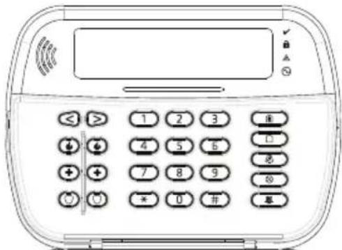
The HS2LED/HS2ICN(P)(RF)x/HS2LCD(RF)(P)x keystads are compatible with the PowerSeries Nco HS2016/32/64, HS2014- 4* and HS2128 panels. The RF keystads combine a wireless transceiver with the respective HS2 keypad.
Specifications
NOTE: Keypads contain no serviceable parts.
NOTE: Only models operating in band 912-919MHz are UL/ULC listed.
Unpack
The keypad package includes the following:
HS2LED/ICN(RF)/LCD(RF)
HS2ICN(RF)P/LCD(RF)P
-1 kcpad -1 kcpad
- 4 mounting screws - 4 mounting screws
- 2 end-of-line resistors - 2 end-of-line resistors
Keypad inner door labels
- 1 tamper switch - 1 tamper switch
Table 1: Compatible Devices
| Wireless PG smoke detector | PGx926UL |
| Wireless PG smoke and heat detector | PGx916UL |
| Wireless PG CO detector PGx913 | |
| Wireless PG PIR motion detector PGx904(P) | UL |
| Wireless PG PIR + camera motion detector | PGx934(P)UL |
| Wireless PG curtain motion detector | PGx924UL |
| Wirelccss PG dual tech motion detector PGx984(P) | |
| Wireless PG mirror motion detector PGx974(P) | UL |
| Wireless PG outdoor motion detector | PGx994UL |
| Wireless PG glass break detector PGx912 | |
| Wireless PG shock detector | PGx935UL |
| Wireless PG flood detector | PGx985UL |
| Wirelccss PG temperature dctcctor (indoor) | PGx905UL |
| Outdoor temperature probe (requires PGx905) | PGTEMP-PROBE |
| Wireless PG key | PGx939UL |
| Wireless PG key | PGx929UL |
| Wirelccss PG panic key | PGx938UL |
| Wireless PG 2-button key | PGx949UL |
| Wireless PG indoor siren | PGx901UL |
| Wireless PG outdoor siren | PGx911UL |
| Wirelccss PG repcater | PGx920UL |
| Wirelccss PG door/window contact | PGx975UL |
| Wireless PG door/window contact w/AUX | PGx945UL |
| NOTE: In this chart, x in the model number represents the operating frequency of the device as follows: 9 (912-919 MIIz), 8 (868MHz), 4 (433MHz). |
| NOTE: Only models operating in the band 912-919 MIIz are UL/ULC or cUL listed where indicated. Only UL approved devices arc to be used with UL/ULC listed systems. |
Mount
Mount the keypad where it is accessible to designated points of entry and exit. Once a dry and secure location is selected, perform the following steps to mount the keypad.
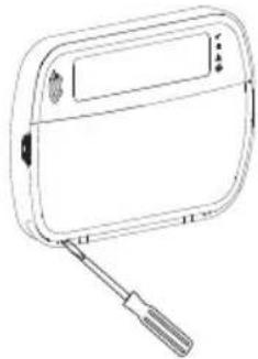
Disassemble Keypad
- Insert the tip of a flat-head screwdriver into the slots at the bottom lcf and right of the kypad.
- Gently pry open the faceplate. This will remove it and allow access for mounting.
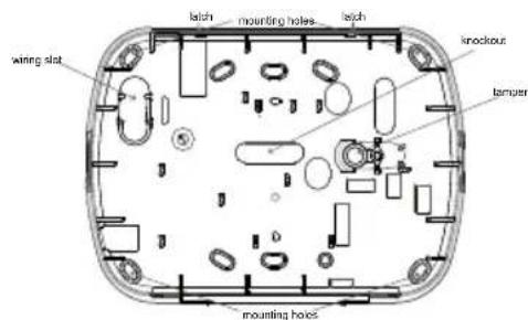
Mount and Wire Keypad
- Secure keypad to wall using mounting holcs. Use all four screws provided unless mounting on a single gang box. Use the plastic anchors supplied if the unit is to be mounted on drywall.
- If using the keypad tamper, secure the tamper plate to the wall with a screw.
NOTE: For UL/ULC listed commercial burglary installations, the use of the keypad tamper is mandatory.
- Run wire through wiring slot or knockouts. Connect Corbus and PGM/Zone wiring to keypad. Place tamper switch into tamper hole on backplate.
- Place keypad into backplate, ensuring the wire is pushed back into the wall as much as possible. Route the wire inside the keypad, ensuring high components are avoided. Snap the front assembly closed, ensuring that there is no pressure to the keypad from the wire below.
NOTE: If any tension is found between the front keypad assembly and the wiring, open the keypad, reroute the wire and close again. Repcat thscst steps until the keypad is closed properly.
Wiring
- Before wiring the unit, ensure that all power (AC transformer and battery) is disconnected from the control panel.
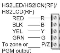
- Connect the four Corbus wires from the control panel (red, black, yellow and green) to the keypad terminals. Refer to the diagram:
-
If programmed as an input, a device - such as a door contact
-
may be connected to the 'P/Z' terminal of the keypad. This eliminates the need to run wires back to the control panel for the device. To connect the zone, run one wire from the device to the 'P/Z' terminal and the other wire from the device to the B (black) terminal. For powered devices, run the red wire to the R (positive) terminal and the black wire to the B (negative) terminal. When using end of line supervision, connect the zone according to one of the configurations described in the PowerSeries Neo Reference manual.
NOTE: For UL/ULC installations, the zone input is a supervised type (SEOL/DEOL). The supervision resistor is 5600 . If no EOL supervision is used, there is a three foot maximum distance required for the connected device. Use only in conjunction with UL/ULC listed devices.
NOTE: This initiating device connected to this input contact is not to be used for medical or fire applications.
- If the P / Z^ terminal is programmed as an output, a small relay (such as DSC model RM-1 or RM-2) or buzzer or other DC operated device may be connected between the positive supply voltage and the P / Z^ terminal (max.load is 50mA ).
NOTE: For UL/ULC-listed installations, use UL/ULC listed devices.
Apply Power
Once all wiring is complete, and the equipment is secured to the building structure with at least two serews, apply power to the control panel:
- Connect the battery leads to the battery.
- Connect the AC transformer
For more information on control panel power specifications, see the PowerSeries Neo Reference manual.
Program the Keypad
- Press [^*][8][ Installer Code].
- Use the [<][>] keys to navigate through the menus or jump directly to a specific section by entering the section number.
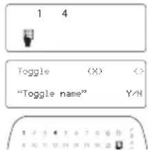
Programming consists of toggling on and off options in each section or by populating data fields. Toggle options are enabled or disabled by pressing the corresponding number on the keypad. For example, to enable toggle options 1 and 4, press the [1] and [4] keys. All enabled options are displayed (see the following diagram).
- To input data, use the [<][>] keys to select a character then press the keypad button for the number/letter.
- Using the |<|>>| keys, scroll to the next character and repeat the procedure. For information on entering IEX data, refer to the PowerSeries Neo Reference manual.
Language Programming
Enter [000][000]. Enter the two-digit number corresponding to the language desired:
Table 2: Languages
| 01 = English
(default) | 10 = German 20 = Romanian |
| 11 = Swedish 21 = Russian |
| 02 = Spanish 12 = Norwegian 22 = Bulgarian |
| 03 = Portuguese 13 = Danish 23 = Latvian |
| 04 = French 14 = Hebrew 24 = Lithuanian |
| 05 = Italian 15 = Greek 25 = Ukrainian |
| 06 = Dutch | 16 = Turkish | 26 = Slovak |
| 07 = Polish | 17 = FFU | 27 = Serbian |
| 08 = Czech | 18 = Croatian | 28 = Estonian |
| 09 = Finnish | 19 = Hungarian | 29 = Slovenian |
Enroll the Keypad
Keypads can be enrolled automatically or manually. In either case, the serial number of the device is used as an identifier.
NOTE: If there is no keypad enrolled on the system, once you power up, the keypad will display the message: Press any key to enroll. Other keypads can then be enrolled from the first keypad. Use one of the following enrollment options:
[902][000] Auto Enroll
When this mode is selected, the total number of keypoints currently crolled is displayed on the kypad.
1. Enter [902][000] to begin the auto-enrollment of new keypads. As each device is enrolled, the keypad displays the model type, serial number and slot assignment. Keypads are assigned to the next available slot.
[902][001] Manual Enrollment
To manually enroll individual keypads:
- Enter [902][001] or use the [ ][ ] keys and press [^*]
- When prompted, enter the serial number of the kcpad found on the back of the device.
- An error tone is sounded if an invalid serial number is received. Once enrolled, the device model, serial number and slot assignment are displayed. Keycaps are enrolled into the next available slot for the device. The slot assignment can be changed using the |<|>| keys.
- To cancel the enrollment of a module, press [#].
NOTE: Once the maximum number of devices have been enrolled, an error tone sounds and a warning message is displayed. [902][002] - Module Slot Assignment (LED, LCD, ICON) This section is used to change the slot number in which a module is enrolled. To change the slot number: 1. Enter [902][002] or use the |<||>| keys and press [^*] .
-
Enter the serial number of the module.
-
When prompted, enter the new two-digit slot number. The previous slot assignment is replaced with the new one. An error tone sounds if an invalid slot number is entered.
[902][003] - Module Slot Assignment (LCD Keypad)
Only)
Similarly to [002], this section is also used to change the slot number of a module. With this option, however, the serial number is not required. To change the slot number:
1. Enter [902][003] or the use the [< ][>] keys and press [ ]
2. Use the |<|>| keys to locate the module then press [^*] to select.
3. Enter the new two-digit slot number. The previous slot assignment is replaced with the new one. An error tone sounds if an invalid slot number is entered.
[902][101] Unenroll Keypads
- Enter [902][101] or use the [<][>] keys and press [] .
- Use the | < || > | keys to scroll to the specific keypad to delete.
- Press [^] to select the module and when prompted, press [^] again to delete it.
[903][101] Confirm Keypad
To confirm the enrollment of individual keystads and to locate them physically:
- Enter [903][101] or use the [ ][ ] and press [ ]
- Use the < > keys to scroll to the applicable keypad. The module's serial number and slot number are displayed on the keypad and the status LEDs on the device flash.
- To confirm the keypad, press [^*] . If communication with a module is lost at the time of confirmation, a warning message is displayed for 1 second before exiting the section.
Assign a Partition to the Keypad
The keypad must be assigned to a partition if supervision or keypad zones are required. Keypad assignments and keypad option programming must be done at each keypad individually.
At each keypad installed on the system:
At each key position, install on the 1. Prcess [+][8][] Installer Codel.
2. Enter [861]-[876] for Keypad Programming and Keypad Partition Mask, corresponding to keypads 1-16.
3. Press [^*] for partition assignment.
4. Enter 01 to 08 for partition assignment or use the [<][>] keys to scroll to the specific partition if partitioning is not used, enter [01]. For Global kcpads, enter [00].
5. Press [#] twice to exit programming.
6. Continue this procedure for each keypad until all have been assigned to the correct partition.
Program Labels (LCD keypads only)
- Press [*][8] [Installer Code].
-
Press [^] and use the [<][>] keys to scroll to Zone Labels and press [^] again. The first zone is displayed. Alternatively, enter, [000][001].
-
Use the [ < ][ > ] keys to scroll to the zone label to be programmed and press [^*] or enter the zone number (e.g., 001, for zone label 1).
- Use the |<||>| keys to scroll to the desired character's location, using the |<||>| keys.
- Enter the number of the corresponding character group until the desired character is displayed (see the following table). Example, press the "2" key three times to enter the letter "F". Press the "2" key four times to enter the number "2". Press [*], then scroll to "Save". Press [+]
| [1] - A, B, C, 1 | [5] - M, N, O, 5 | [9] - Y, Z, 9, 0 |
| [2] - D, E, F, 2 | [6] - P, Q, R, 6 | [0] - Space |
| [3] - G, H, I, 3 |7 | -S, T, U, 7 | [*] - Select |
| [4] - J, K, L, 4 [8] | -V, W, X, 8 | [#] - Escape |
again to save the label. To delete a character, use the [<][>] keys to move the cursor under the character, then press [0]. If any key other than [<][>] is pressed before [0], the cursor moves one space to the right and deletes that character.
CHANGE CASE - Will toggle the next letter entries between upper case (A, B, C...) and lower case letters (a, b, c...).
ASCII ENTRY - Used to enter uncommon characters. Valid entries range from 000 to 255. Use the [<] keys to scroll through the characters or enter a 3-digit number from 000-255. Press [^*] to enter the character into the label.
CLEAR TO END - Clears the display from the character where the cursor was located to the end of the display.
CLEAR DISPLAY -Clears the entire label.
6. Continue from Step 2, until all labels are programmed.
Label Library
The Label Library is a database of words commonly used when programming labels. Individual words can be combined as needed (e.g., Front + Door). Each line of the display supports a maximum of 14 characters. If a word will not fit on a line, scroll right until the cursor appears at the first character of the second line and then add the word. To program a custom label using the Label Library:
- Press [^*][8][Installer Code][000][001] .
- Enter [001] (to program the label for zone 01), or use the [< ][> keys to scroll to the Zone Labels and then press | . The current label name is displayed for that zone.
- Press [^] to open the menu.
- Press again to select the "Word Entry" option.
- Enter the 3-digit number corresponding to a word (see Words Library) or use the [< ][> keys to view words in the library.
- Press [] to select the word.
- To add another word, repeat the previous procedures from step 3.
- To add a space, press the right scroll key [>] .
- To clear characters, select "Clear to End" or "Clear Display" from the menu.
10.To save the current label and exit, press [].
Broadcast LCD Labels
If more than one LCD keypad is present on the system, labels programmed on one keypad will be broadcast to all other LCD keypads, after the change is confirmed.
Change Brightness/Contrast/Buzzer
LCD Keypads
- Press [^*][6][Master Code] .
- Use the [< ][>] keys to scroll to either Bright Control, Contrast Control, or Buzzer Control.
- Press [^*] to select one of the following settings:
- Brightness/LED Bar Control: 15 backlighting levels are available.
- Contrast Control: 15 different display contrast levels are available.
- Buzzer Control: 15 different buzzer control levels are available.
- Use the [<][>] keys to scroll to the desired setting.
Keypad Programming
-
Press [*][8][Installer Code].
-
Select one of the programming options identified in the following.
[860] Keypad Slot Number
Not for programming; the two-digit slot number is displayed for informational purposes only.
[861]-[876] Keypad Programming Sections
[000] Address of Partition
A 2-digit entry is required to assign the keypad to a partition. Entering 00 assigns the keypad as Global, Valid entries are 00-32. The default is 01.
[001]-[005] Keypad Function Key Programming
To program a function key:
1. Press [^][8][ Installer Code].
2. Enter [861]-[876] for keypad programming.
3. Enter [001]-[005] for function keys 1-5 or use the [ ][ ] keys and press [^]
4. Enter a 2-digit number to assign a function key operation - [00]-[68]. See the following table.
5. Repeat from step 3 until all function keys are programmed.
6. Press [#] twice to exit Installer Programming.
[001]-[005] Function Key Assignment
| Function Key | Button | Valid Range | Default Function |
| [001] | Key 1 | 00-68 | 03 Stay Arm | _ | _ | _ |
| [002] | Key 2 | 00-68 | 04 Away Arm | _ | _ | _ |
| [003] | Key 3 | 00-68 | 06 Chime ON/OFF | _ | _ | _ |
| [004] | Key 4 | 00-68 | 22 Command Output 2 | _ | _ | _ |
| [005] | Key 5 | 00-68 | 16 Quick Exit | _ | _ | _ |
Keypad Function Keys
Refer to your system installation manual for a complete list of available function key options.
[00] - Null [21] - [°][7][1]Command Output 1
[02] - Instant Stay Arm [22] - [][7][2]Command Output 2
[03] - Stay Arm [23] - [][7][3]Command Output 3
[04] - Away Arm [24] - [][7][4]Command Output 4
[05] -[][9] No-Entry Arm [29] - Bypass Group Recall
[06] - [][4] Chime ON/OFF [31] - Local PGM Activate
[07] -*||6|---||4 System Test [32] -Bypass Modc
[09] - Night Arm [33] - Bypass Recall
[12] - Global Stay Arm [34] - User Programming
[13] - Global Away Arm [35] - User Functions
[14] - Global Disarming [37] - Time & Date Program
[16] -[][0] Quick Exit [39] - TroubL Display
[17] - Arm Interior [40] - Alarm Memory
[011] Keypad Input/Output Programming
| Zone or PGM Number | Default 000 | 1 | 1 | 1 |
[012] Local PGM Output Pulse Activation Time
1
Minutes (00-99)
1
Seconds (00-99)
[021] First Keypad Options
Default Opt. ON OFF
ON
1 Fire Key Enabled Fire Key Disabled
ON
2 Medical Key Enabled Medical Key Disabled
ON
3 Panic Key Enabled Panic Key Disabled
4 Display Access Code When Programming
Display Xs When Programming Access Codes
[022] Second Keypad Options
Default Opt. ON OFF
ON 1
1 Local Clock Display ON Local Clock Display OFF
OFF 1 ON
2 Local Clock Displays 24-hrClock Displays AM/PM 3.应收 Alarm Macro Squirrel ON应收 Alarm
ON
4 For Future Issues:
OFF
5 Power LED Enabled
ON
6 Power LED Indicates AC Present ON
ON
7 Alarms Displayed While Armed
OFF
8 Auto-Scroll Open Zones ON
Auto-Scroll Open Zones OFF
[023] Third Keypad Options
Default
Opt. ON
OFF
Armed LED Power Save
ON
Keypad Status Shows Stay Arm
OFF
5th Terminal is Kcypad PGM Output
OFF
Local Display of Temperature
OFF
Low Temperature Warning Enabled
OFF
Armed LED Off in Sleep Mode
Keypad Status Shows Stay/Away Arm
5th Terminal is Keypad Zone Input
No Local Display of Temperature
Low Temperature Warning Disabled
[030] Downloaded LCD Message
![DSC HS2ICN - [030] Downloaded LCD Message - 1](/content/2026/02/416853/images/be51cc66575f2e4713caac9798a619be2fe2b8e103c5312ef7efe7658115aad7.jpg)
[031] Downloaded LCD Message Duration
Default: 000 | | | | | (Valid entries are 000-255, 000=Unlimited Msg Display)
This number represents the number of times the downloaded message must be cleared before it is permanently removed. This message can be cleared by pressing any key.
[041] Indoor Temperature Zone Assignment
Default: 000
1 1 1
(Valid entries are 000-128)
[042] Outdoor Temperature Zone Assignment
Default: 000
1 1 1
(Valid entries are 000-128)
[101]-[228] Door Chime for Zones 1-128
The keypad can be programmed to make up to four different chime sounds for individual zones. (e.g., for Zone 1, enter section [101], for Zone 2 enter section [102]). Default: 01 | 11
Valid Entries
01 6 bccps
02 Bing-Bing tone
03 Ding-Dong tone
04 Alarm tone (4 second duration)
05 Zone name
[991] Reset Keypad Programming to Factory Defaults
- Press [*][8][Installer Code].
- Enter [991].
- Use the [ ][ ] keys to scroll to the applicable keypad.
- Press * to select the key
- Re-enter [Installer Code].
- Press [^*] to reset the selected keypad to factory defaults.
Table 3: Keypad Display Symbols
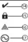
Memory-Indicates that alarms are in mem
ORY.
Fire-Indicates that fire alarms are in mem
P 10.4.2.3.4.5.6.7.8.9.10.11.12.13.14.15.16.17.18.19.20.21.22.23.24.25.26.27.28.29.30.31.32.33.34.35.36.37.38.39.40.41.42.43.44.45.46.47.48.49.50.51.52.53.54.55.56.57.58.59.60.61.62.63.64.65.66.67.68.69.70.71.72.73.74.75.76.77.78.79.80.81.82.83.84.85.86.87.88.89.90.91.92.93.94.95.96.97.98.99.
Clock Digits - These digits indicate the hour
and minutes when the local clock is active,
and also identify the zone when the OPEN or
ALARM icons are active. These digits show are zone non second from the lowest zone.
one zone per second from the lowest zone number to the highest when scrolling through
Zones.
1 to 8-These numbers display toggles or dig
its in binary while they are needed.
Bypass-Indicates that there are zones auto
matically or manually bypassed.
b Open-When zones are opened, this icon will
turn on and the open zones are displayed.
Program-If the system is in Installer's or
User's Programming, or the keypad is busy,
this icon flashes. If an access code is required
while accessing star menus, this LED is on
steadily to indicate that the code is required.
Chime -Turns on when Door Chime is ena+
blcd and off when Door Chime is disabled.
Away-Indicates that the panel is armed in
away mode.
Stay - Indicates that the panel is armed in
stay modc.
Night - Indicates that the panel is armed in
night mode.
Ready Light (green) - If the Ready light is
on, the system is ready for arming.
Armed Light (red) - If the Armed light is
on, the system has been armed successfully.
System Trouble - Indicates that a system
trouble is active.
AC Indicates that AC is present at the
main panel.
The prox tag can perform any keypad function that would normally require a user access code. Present the tag to the tag reader to the left of the keypad LCD.
Using an LCD keyboard:
-
Press [][5][Master/Supervisor Code] .
-
Enter a 2-digit user code
-
Press 2.
-
Pass the enrolled tag near the tag reader on the keypad.
To delete a prox tag, select the user as outlined previously. Swipe the associated prox tag. The alarm system recognizes the tag. Press [^*] to delete when prompted.
LED Bar
On the HS2ICNP/HS2ICNFP/HS2LCDP keypads, a blue LED bar indicates that a prox tag is approaching.
The LED bar flashes three times when a valid prox tag is being read by the keypad.
-
If the prox tag is invalid, the LED bar stays on steadily and the keypad sounds an error tone.
-
The brightness of the LED bar is adjustable from the [^*][6] menu. When the backlight brightness is modified, the LED bar brightness is changed accordingly.
Downloading
The IIS2LCDRF/IIS2ICNRF products can be programmed over DLS V. This auto-detects the key pad type and downloads programming accordingly.
Wireless Device Setup and Programming (HS2ICNRF(P)x/HS2LCDRF(P)x)
This section describes how to enroll and program wireless devices such as contacts, motion sensors and sirns on the alarm panel.
[804][000] Enroll Wireless Devices
-
Once the HSM2HOST is installed and enrolled on the alarm panel wireless devices can be enrolled using the following method: Enter Installer Programming section |804|000|
-
When prompted, either activate the device (see device installation sheet) to enroll immediately or enter a device ID number. Do the latter to pre-enroll devices then enroll them later at the customer site.
The alarm panel determines the type of device being enrolled and presents the appropriate programming options.
Table 4: Wireless Device Options
| Device Type Programming Options |
| Zone | (01) Zone type
(02) Partition assignment
(03) Zone label |
| Wireless key | (01) Partition assignment
(02) User label |
| Siren | (01) Partition assignment
(02) Siren label |
| Repeater (01) Repeater label | |
-
Use the scroll keys or type in the corresponding number to select an option.
-
Scroll through the available selections, key in a number or enter text as appropriate.
-
Press [串] to accept and move to the next option.
-
Once all options are configured, the system prompts to enroll the next device.
-
Repeat the process described above until all wireless devices are enrolled.
NOTE: The configuration options listed above can be modified using [804][911] Modify Device. [804][001]-[716] Wireless Device Configuration
To configure wireless devices:
- Enter Installer Programming section [804] then select one of the following sub-sections:
Table 5: Wireless Zone Sub-Sections
| Sub-Section Description |
| 001-128 Configure wireless zones |
| 551-556 Configure wireless sirens |
| 601-632 Configure wireless keys |
| 701-716 Configure wireless keys pads |
-
Select a device to configure using the scroll keys or go directly to a specific device by entering a hotkey.
-
Use the scroll buttons or enter a hotkey to select a configuration option for the device. See device sheets for details.
-
Press [^*] to accept and move to the next option.
-
Once all options are configured, the system returns to the base configuration menu.
Repeat the process described above to configure other wireless devices.
[804][801] RF Jam Detect
RF jam detection (continuous interfering transmissions on the radio network) can be turned on or off. When on, RF jamming is logged and reported.
To configure RF jamming:
-
Enter Installer Programming section [804][801].
-
Select one of the following options by scrolling or entering the hotkey:
Table 6: Jam Detect Options
| 00 Enabled | d/Disabled | Jamming detection and reporting is enabled/disabled
Note: Must be Enabled for UL/ULC listed installations. |
| 01 UL 20/20-USA Continuous RF jamming for 20 seconds |
| 02 EN 30/60-Europe 30 seconds of accumulated jamming within 60 seconds |
| 03 Class | 6 30/60-British | As EN (30/60) but reported only if the jamming duration exceeds 5 minutes |
-
Press [^*] to accept the selection.
-
Press [#] to exit the section.
[804][802] Wireless Supervision Window
This option is used to program the length of time a wireless device can be absent from the system before a fault is generated.
NOTE: For EN installations, 1 hour or 2 hours must be selected.
When option 06 is used, which configures the system to generate fault conditions after a device has been detected as absent for 24 hours, smoke detectors generate a fault condition after a maximum of 18 hours when the 200s supervision toggle option is disabled.
To program the Wireless Supervisory Window: 1. First, Install the Progrive
-
Enter Installer Programming section [804][802].
-
Select one of the following options by scrolling or entering the hotkey:
Table 7: Wireless Supervisory Window Options
| 00 Enabled/Disabled |
| 01 After 1 Hour |
| 02 After 2 Hour |
| 03 After 4 Hour |
| 04 After 8 Hour |
| 05 After 12 Hour |
| 06 After 24 Hour |
-
Press [^*] to accept the selection.
-
Press [#] to exit the section.
NOTE: For UL Residential Burglary (UL1023), Home Health Care (UL1637), ULC Residential Burglary (ULC/ORD-C1023) installations, the maximum Supervision window shall be set to 24 hours.
For UL Residential Firc (UL985) installations, the maximum supervision window is set to 200s. For UL Commercial Burglary (UL1610/UL365) and ULC Residential Fire (ULC-S545), the maximum supervision window shall be set to 4 hours.
[804][810] Wireless Option 1
To program wireless options:
1. Enter Installer Programming section [804][810].
2. Select one of the following options by scrolling or entering the hotkey:
Table 8: Wireless Options
| 01 RF | Delinquency | On: the system cannot bc armed if a wireless supervisory trouble exists. An RF delinquency trouble is generated. Off: wireless supervisory troubles do not prevent arming. |
| 02 | Wireless Supervisory/ RF Jam Alarm | On: if a supervisory or jamming trouble occurs during Away arming, the siren activates and the event is logged and reported. Off: supervisory or RF jam troubles during Away arming do not activate the siren or get logged and reported. |
| 03 Module Tamper | On: module tampers are logged and reported. Off: module tampers are not logged or reported. |
| 04 Fire | Supervision | On: fire devices are supervised every 200 seconds. If the device fails to report within this window, a supervision trouble is generated. Off: fire devices follow the supervision window programmed in section 802, up to a maximum of 18 hours. The supervisory window can be programmed with a higher value, but detectors still go into fault after 18 hours. |
- Press [^*] to accept the selection and [# ] to exit.
[804][841] Visual Verification Programming
To program wireless options:
- Enter Installer Programming section [804][841].
- Select one of the following options by scrolling or entering the hotkey:
Table 9: Visual Verification Sub-Sections
| 001 Visual Verification | On: Alarms trigger image capture from PIR Cameras
Off: Alarms do not trigger image capture from PIR Cameras |
| 002 View Time Window | 01 Alarm + 5 Minutes
02 Alarm + 15 minutes
03 Alarm + 1 Hour |
| 003 View Other Alarms | 01 Fire key enabled/disabled
02 Duress key enabled/disabled
03 Medical key enabled/disabled
04 Panic key enabled/disabled |
[804][901]-[905] Delete Wireless Devices
To delete wireless devices
- Enter Installer Programming section [804] then select one of the following sub-sections:
Table 10: Module Label Sub-Sections
| Sub-Section Description |
| 901 Delete wireless zone devices |
| 902 Delete wireless key | |
| 903 Delete sirens | |
Table 10: Module Label Sub-Sections
| 904 Delete repeaters | |
| 905 Delete keypads | |
- Select a device to delete using the scroll keys or go directly to a specific device by entering a hotkey.
- Press [^*] to delete or [# ] to exit
[804][921]-[925] Replace Wireless Devices
Use this option to replace a faulty device enrolled on the system with another device of the same type. While maintaining the configuration of the original. The faulty device does not need to be deleted.
To replace a wireless device:
- Enter Installer Programming section [804] then select one of the following sub-sections:
Table 11: Replace Device Sub-Sections
| Sub-Section Description |
| 921 Replace wireless zone devices |
| 922 Replace wireless keys | |
| 923 Replace sirens | |
| 924 Replace repeater | |
| 925 Replace keypad | |
-
Press [^*] to select a sub-section. The first available device is displayed.
-
Select a device to replace using the scroll keys or go to a specific device by entering a hotkey. Press [^*] . When prompted, activate the device (full enrollment) or enter the device ID (pre-enrollment). A message is displayed confirming enrollment.
[804][990][001-005] Show All Devices
Use this section to review wireless devices enrolled on the system and to view serial numbers associated with each device.
To review wireless device information:
- Enter Installer Programming section [804][990] then select one of the following sub-sections: [001] all zones
[002] - repeaters
·[003] ciirrs
[003] -sirens 1964
- [004] - wireless keys
- [005] - keystads
-
Press [^*] to select a wireless device type. The first available device is displayed.
-
Use the scroll keys to view the enrolled devices.
NOTE: This option is not fully supported by LED and ICON keypads.
[904] Placement Testing Wireless Devices
This test is used to determine RF signal status for wireless devices and can be performed at a system keypad or at the individual device. These instructions pertain to testing at the keypad. For instructions on placement testing at the device, refer to the installation sheet provided with the wireless equipment. The following test modes are available:
Table 12: Wireless Device Placement Test Modes
| 001-128 Test wireless zones Test wireless devices individually by zone. |
| 520 Test | all repeaters | Test each enrolled wireless repeater. 521-528 for repeaters 1-8 |
| 550 Test | all sirens | Test each enrolled wireless siren. 551-556 for sirens 1-16 |
| 600 Test | all wireless keys | Test individual wireless keys. Once in this section, press a button on the wireless key to begin the test. 601-632 for wireless keys 1-32. |
Table 12: Wireless Device Placement Test Modes
| 700 Test | all kcpads | Test each enrolled keypad
701-716 for keypads 1-16 |
Two test results are provided:
24-hour: Average results of signal strength testing over a 24-hour period.
- Now: Signal status results of the current test.
During testing, the Ready and Armed LED's flash to indicate data is being received. A flashing Trouble LED indicates RF interference. The following status indicators may be displayed:
Table 13: Wireless Device Status Indicators
| LCD Icon* LED+ Status Repeater [905] | |
| Strong 1 9 Strong signal strength Repeater 1 | |
| Good 2 10 Good signal strength Repeater 2 | |
| Poor 3 11 Poor signal strength Repeater 3 | |
| 1-Way 4 12 | | | The device is operating in 1-way mode only. The alarm panel cannot configure or control the device | Repeater 4 |
| Not Test | 5 13 | | Displayed as the Now result if no test was performed. | Repeater 5 |
| None | | 14 | Always displayed as the 24-hour result when testing wireless keys. | Repeater 6 |
NOTE: For UL/ULC installations, only STRONG signal levels are acceptable.
*For Icon keyboards, digit 1 indicates 24-hour test results; digit 2 indicates Now test results.
+For LED keypads, the first digit indicates 24-hour results; the second digit indicates Now test results.
Troubleshooting
-
When attempting to assign a zone number to a wireless device, the kcpad responds with a long beep.
-
Ensure that the keypad is properly connected to the Corbus.
-
After entering the ESN of a wireless device, then tripping it, the keypad does not indicate the zone is open.
-
Ensure the ESN has been entered correctly.
-
Ensure that the zone is enabled for the partition (if partition programming is used).
- Ensure that the wireless zone is not assigned to a zone used by IISM2108 modules, an on-board zone or a keypad zone.
- Ensure that the zone is programmed for something other than "Null Operation". "Poor" or no results are received from a module placement test.
- Verify that you are testing the correct zone.
- Verify that the device is in range of the keypad. Try testing the device in the same room as the receiver.
- Confirm that the keypad is properly connected to the Corbus.
- Check that the zone is being tested correctly. Refer to the instructions that came with the device.
- Check that the batteries are working and installed correctly.
- Look for large metal objects that may be preventing the signal from reaching the keypad.
- The device must be located where consistent "Good" results are obtained. If several devices show "Poor" results, or if panic pendants and wireless keys operate inconsistently, move the receiver.
NOTES:
Word Library
| Item # Text Item # Text Item # Text Item # Text Item # Text |
| 001 Aborted | 042 Control 083 Garage 124 Mo | ion 165 Shock 206 D | | | | | | | | |
| 002 | AC | 043 | Date | 084 | Gas | 125 | No | 166 | Shop | 207 |
| 003 | Access | 044 | Daughter's | 085 | Glass | 126 | North | 167 | Side | 208 |
| 004 Active | 045 Degrees 086 Goodbye 127 Not | 168 Siren | | 209 G | | | | | | |
| 005 | Activity | 046 | Dclay | 087 | Gym | 128 | Now | 169 | Sliding | 210 |
| 006 Alarm | 047 Den | | 088 Hallway 129 | Number 170 Smoke 211 I | | | | | | |
| 007 | All | 048 | Desk | 089 | Heat | 130 | Off | 171 | Son's | 212 |
| 008 | AM | 049 | Dctector | 090 | Hello | 131 | Office | 172 | Sound | 213 |
| 009 | Area | 050 | Dining | 091 | Help | 132 | OK | 173 | South | 214 |
| 010 | Arm | 051 | Disarmed | 092 | High | 133 | On | 174 | Special | 215 |
| 011 | Armed | 052 | Door | 093 | Home | 134 | Open | 175 | Stairs | 216 |
| 012 | Arming | 053 | Down | 094 | House | 135 | Opening | 176 | Stay | 217 |
| 013 | Attic | 054 | Download | 095 | In | 136 | Panic | 177 | Sun | 218 |
| 014 | Auxiliary | 055 | Downstairs | 096 | Install | 137 | Partition | 178 | Supervisory | 219 |
| 015 | Away | 056 | Drawer | 097 | Interior | 138 | Patio | 179 | System | 220 |
| 016 | Baby | 057 | Driveway | 098 | Intrusion | 139 | Pet | 180 | Tamper | 221 |
| 017 | Back | 058 | Duct | 099 | Invalid | 140 | Phone | 181 | Temperature | 222 |
| 018 | Bar | 059 | Duress | 100 | s | 141 | Please | 182 | Test | 223 |
| 019 | Basement | 060 | East | 101 | Key | 142 | PM | 183 | Time | 224 |
| 020 | Bathroom | 061 | Energy | 102 | Kids | 143 | Police | 184 | To | 225 |
| 021 | Battery | 062 | Enter | 103 | Kitchen | 144 | Pool | 185 | Touchpad | 226 |
| 022 | Bedroom | 063 | Entry | 104 | Latchkey | 145 | Porch | 186 | Trouble | 227 |
| 023 | Bonus | 064 | Error | 105 | Laundry | 146 | Power | 187 | Unbypass | 228 |
| 024 | Bottom | 065 | Exercise | 106 | Left | 147 | Press | 188 | Unit | 229 |
| 025 | Breczeway | 066 | Exit | 107 | Level | 148 | Program | 189 | Up | 230 |
| 026 | Building | 067 | Exterior | 108 | Library | 149 | Progress | 190 | West | 231 |
| 027 | Bus | 068 | Factory | 109 | Light | 150 | Quiet | 191 | Window | 232 |
| 028 | Bypass | 069 | Failure | 110 | Lights | 151 | Rear | 192 | Zone | 233 |
| 029 | Bypassed | 070 | Family | 111 | Living | 152 | Receiver | 193 | 0 | 234 |
| 030 | Cabinet | 071 | Father's | 112 | Load | 153 | Report | 194 | 1 | 235 |
| 031 | Canceled | 072 | Feature | 113 | Loading | 154 | RF | 195 | 2 | 236 |
| 032 | Car | 073 | Fence | 114 | Low | 155 | Right | 196 | 3 | 237 |
| 033 | Carbon | 074 | Fire | 115 | Lower | 156 | Room | 197 | 4 | |
| 034 | Central | 075 | First | 116 | Main | 157 | Safe | 198 | 5 | |
| 035 | Chime | 076 | Floor | 117 | Master | 158 | Saver | 199 | 6 | |
| 036 | Closed | 077 | Force | 118 | Mat | 159 | Schedule | 200 | 7 | |
| 037 | Closet | 078 | Foyer | 119 | Medical | 160 | Screen | 201 | 8 | |
| 038 | Closing 079 Freeze | | 20 Memory 161 Second 202 9 | | | | | | | |
| 039 | Code | 080 | Front | 121 | Menu | 162 | Sensor | 203 | A | |
| 040 | Communicator | 081 | Furnace | 122 | Monoxide | 163 | Service | 204 | B | |
| 041 | Computer | 082 | Gallery | 123 | Mother's | 164 | Shed | 205 | C | |
Limited Warranty
Digital Security Controls (DSC) warrants that for a period of 12 months from the date of purchase, the product shall be free of defects in materials and workmanship under normal use and that in fulfillment of any breach of such warranty, DSC shall, at its option, repair or replace the defective equipment upon return of the equipment to its repair depot. This warranty applies only to defects in parts and workmanship and not to damage incurred in shipping or handling, or damage due to causes beyond the control of Digital Security Controls such as lightning, excessive voltage, mechanical shock, water damage, or damage arising out of abuse, alteration or improper application of the equipment. The foregoing warranty shall apply only to the original buyer, and is and shall be in lieu of any and all other warranties, whether expressed or implied and of all other obligations or liabilities on the part of Digital Security Controls. Digital Security Controls neither assumes responsibility for, nor authorizes any other person purporting to act on its behalf to modify or to change this warranty, nor to assume for it any other warranty or liability concerning this product. In no event shall Digital Security Controls be liable for any direct, indirect or consequential damages, loss of anticipated profits, loss of time or any other losses incurred by the buyer in connection with the purchase, installation or operation or failure of this product. WARNING: Digital Security Controls recommends that the entire system be completely tested on a regular basis. However, despite frequent testing, and due to, but not limited to, criminal tampering or electrical disruption, it is possible for this product to fail to perform as expected. IMPORANT INFORMATION: Changes/modifications not expressly approved by DSC could void the user's authority to operate this equipment.
IMPORTANT - READ CAREFULLY: DSC Software purchased with or without Products and Components is copyrighted and is purchased under the following license terms:
This End-User License Agreement ("EULA") is a legal agreement between You (the company, individual or entity who acquired the Software and any related Hardware) and Digital Security Controls, a division of Tyco Safety Products Canada Ltd. ("TSC"), the manufacturer of the integrated security systems and the developer of the software and any related products or components ("HARDWARE") which You acquired.
If the DSC software product ("SOFTWARE PRODUCT" or "SOFTWARE") is intended to be accompanied by HARDWARE, and is NOT accompanied by new HARDWARE, You may not use, copy or install the SOFTWARE PRODUCT. The SOFTWARE PRODUCT includes computer software, and may include associated media, printed materials, and "online" or electronic documentation.
Any software provided along with the Software Product that is associated with a separate end-user license agreement is licensed to You under the terms of thal license agreement. By installing, copying, downloading, storing, accessing or otherwise using the Software Product, You agree unconditionally to be bound by the terms of this EULA, even if this EULA is deemed to be a modification of any previous arrangement or contract. If You do not agree to the terms of this EULA, DSC is unwilling to license the Software Product to You, and You have no right to use it.
SOFTWARE PRODUCT LICENSE
The SOFTWARE PRODUCT is protected by copyright laws and international copyright treaties, as well as other intellectual property laws and treaties. The SOFTWARE PRODUCT is licensed, not sold.
- GRANT OF LICENSE This EULA grants You the following rights:
(a) Software Installation and Use - For each license You acquire, You may have only one copy of the SOFTWARE PRODUCT Installed.
(b) Storage/Network Use - The SOFTWARE PRODUCT may not be installed, accessed, displayed, run, shared or used concurrently on or from different computers, including a workstation, terminal or other digital electronic device ("Device"). In other words, if You have several workstations, You will have to acquire a license for each workstation where the SOFTWARE will be used.
(c) Backup Copy - You may make back-up copies of the SOFTWARE PRODUCT, but You may only have one copy per license installed at any given time. You may use the back-up copy solely for archival purposes. Except as expressly provided in this EULA, You may not otherwise make copies of the SOFTWARE PRODUCT, including the printed materials accompanying the SOFTWARE.
2.DESCRIPTION OF OTHER RIGHTS AND LIMITATIONS
(a) Limitations on Reverse Engineering, Decomposition and Disassembly - You may not reverse engineer, decompose, or disassemble the SOFTWARE PRODUCT, except and only to the extent that such activity is expressly permitted by applicable law notwithstanding this limitation. You may not make any changes or modifications to the Software, without the written permission of an officer of DSC. You may not remove any proprietary notices, marks or labels from the Software Product. You shall instil reasonable measures to ensure compliance with the terms and conditions of this EULA.
(b) Separation of Components - The Software Product is licensed as a single product. Its component parts may not be separated for use on more than one HARDWARE unit. (c) Single INTEGRATED PRODUCT - If You acquired this SOFTWARE with HARDWARE, then the SOFTWARE PRODUCT is licensed with the HARDWARE as a single integrated product. In this case, the SOFTWARE PRODUCT may only be used with the HARDWARE as set forth in this EULA.
(c) Rental - You may not rent, lease or lend the SOFTWARE PRODUCT. You may not make it available to others or post it on a server or web site.
(e) Software Product Transfer - You may transfer all of Your rights under this EULA only as part of a permanent sale or transfer of the HARDWARE, provided You retain no copies. You transfer all of the SOFTWARE PRODUCT (including all component parts, the media and printed materials, any upgrades and this EULA), and provided the recipient agrees to the terms of this EULA. If the SOFTWARE PRODUCT is an upgrade, any transfer must also include all prior versions of the SOFTWARE PRODUCT.
(f) Termination - Without prejudice to any other rights, DSC may terminate this EULA if You fail to comply with the terms and conditions of this EULA, in such event, You must destroy all copies of the SOFTWARE PRODUCT and all of its component parts.
(g) Trademarks - This EULA does not grant You any rights in connection with any trademarks or service marks of DSC or its suppliers.
-
Copyright - All title and intellectual property rights in and to the SOFTWARE PRODUCT (including but not limited to any images, photographs, and text incorporated into the SOFTWARE PRODUCT), the accompanying printed materials, and any copies of the SOFTWARE PRODUCT are owned by DSC or its suppliers. You may not copy the printed materials accompanying the SOFTWARE PRODUCT. All title and intellectual property rights in and to the content which may be accessed through use of the SOFTWARE PRODUCT are the property of the respective content owner and may be protected by applicable copyright or other intellectual property laws and treaties. This EULA grants You no rights to use such content. All rights not expressly granted under this EULA are reserved by DSC and its suppliers. 4. EXPORT RESTRICTIONS - You agree that You will not export or re-export the SOFTWARE PRODUCT to any country, person, or entity subject to Canadian export restrictions. 5. CHOICE OF LAW - This Software License Agreement is governed by the laws of the Province of Ontario, Canada.
-
ARBITRATION - All disputes arising in connection with this Agreement shall be determined by final and binding arbitration in accordance with the Arbitration Act, and the parties agree to be bound by the arbitrator's decision. The place of arbitration shall be Toronto, Canada, and the language of the arbitration shall be English.
LIMITED WABBAN
(a) NO WARRANTY. DSC PROVIDES THE SOFTWARE "AS IS" WITHOUT WARRANTY. DSC DOES NOT WARRANTY THAT THE SOFTWARE WILL MEET OUR REQUIREMENTS OR THAT OPERATION OF THE SOFTWARE WILL BE UNINTERRUPTED OR ERROR-FREE.
(b) CHANGES IN OPERATING ENVIRONMENT - DSC shall not be responsible for problems caused by changes in the operating characteristics of the HARDWARE, or for problems in the interaction of the SOFTWARE PRODUCT with non-DSC-SOFTWARE or HARDWARE PRODUCTS.
(c) LIMITATION OF LIABILITY. WARRANTY REFLECTS ALLOCATION OF RISK - IN ANY EVENT. IF ANY STATUTE IMPLES WARRANTY OR CONDITIONS NOT STATED IN THIS LICENSE AGREEMENT, DSC'S ENTIRE LIABILITY UNDER ANY PROVISION OF THIS LICENSE AGREEMENT SHALL BE LIMITED TO THE GREATER OF THE ANOUNT ACTUALLY PAID BY YOU TO LICENSE THE SOFTWARE PRODUCT AND FIVE CANADIAN DOBS (CAD$500). BECAUSE SOME JURISDICTIONS DO NOT ALLOW THE EXCLUSION OR LIMITATION OF LIABILITY FOR CONsequential OR INCIDENTAL DAMAGES, THE ABOVE LIMITATION MAY NOT APPLY TO YOU.
DISCLAIMER OF WARRANTY: THIS WARRANTY CONTAINS THE ENTIRE WARRANTY AND SHALL BE IN LEIEU OF ANY AND ALL OTHER WARRANTY, WHETHER EXPRESSED OR IMplied (INCLUDING IMPLIED WARRANTY OF MERCHANTABILITY OR FITNESS FOR A PARTICULAR PURPOSE) AND OF ALL OTHER OBLIGATIONS OR LIABILITIES ON THE PART OF DSC. DSC MAKES NO OTHER WARRANTY. DSC NEITHER ASSUMES NOR AUTHORIZES ANY OTHER PERSON PURPORTING TO ACT ON ITS BEHALF TO MODIFY OR TO CHANGE THIS WARRANTY. NOR TO ASSUME FOR IT ANY OTHER WARRANTY OR LIABILITY CONCERNING THIS SOFTWARE PRODUCT.
(6) EXCLUSIVE REMEDY AND LIMITATION OF WARRANTY - UNDER NO CIRCUMSTANCES SHALL DSC BE TAXABLE FOR ANY SPECIAL, INCIDENTAL, CONSEQUENTIAL OR INDIRECT DAMAGE BASED UPON BREACH OF WARRANTY, BREACH OF CONTRACT, NEGLIGENCE, STRICT LIABILITY, OR ANY OTHER LEGAL THEORY SUCH DAMAGES INCLUDE, BUT ARE NOT LIMITED TO, LOSS OF PROFITS, LOSS OF THE SOFTWARE PRODUCT OR ANY ASSOCIATED EQUIPMENT, COST OF CAPITAL, COST OF SUBSTITUTE OR REPEACEMENT EQUIPMENT, FACILITIES OR SERVICES, DOWN TIME, PURCHASES TIME, THE CLAIMS OF THIRD PARTIES, INCLUDING CUSTOMERS, AND INJURY TO PROPERTY.
WARNING: DSC recommends that the entire system be completely tested on a regular basis. However, despite frequent testing, and due to, but not limited to, criminal tampering or electrical disruption, it is possible for this SOFTWARE PRODUCT to fail to perform as expected. FCC Compliance Statement - CAUTION. Changes or modifications not expressly approved by DSC could void your authority to use this equipment.
This equipment generates and uses radio frequency energy and if not installed and used properly, in strict accordance with the manufacturer's instructions, may cause interference to radio and television reception. It has been type tested and found to comply with the limits for
Class B device in accordance with the specifications in Subpart "B" of Part 15 of FCC Rules, which are designed to provide reasonable protection against such interference in any residential installation. However, there is no guarantee that interference will not occur in a particular installation. If this equipment does cause interference to television or radio reception, which can be determined by turning the equipment off and on, the user is encouraged to try to correct the interference by one or more of the following measures:
Re-orient the receiving antenna
Relocate the alarm control with respect to the receiver
If necessary, the user should consult the dealer or an experienced radio/television technician for additional suggestions. The user may find the following booklet prepared by the FCC helpful: "How to Identify and Resolve Radio/Television Interference Problems". This booklet is available from the U.S. Government Printing Office, Washington, D.C. 20402, Stock # 004-000-00345-4.
Operating Instructions shall be made available to the user
Models:HS2LCDRF9,HS2LCDRF9H52CINRF9,H52CNFFP9 operating in 912- 919MHz band are compliant with applicable FCC Part 15.27 and IC RSS 210 rules.
WARNING! To comply with FCC and IC RF exposure compliance requirements, the HS2LC-DRF(P)9 or HS2CNRF(P)9 key pads should be located at a distance of at least 20 cm from all persons during
normal operation. The antennas used for this product must not be co-located or operated in conjunction with any other antenna or transmitter.
This device complies with FCC Rules Part 15 and with Industry Canada license-exempt RSS standards.(1). Operation is subject to the following two conditions: (1) This device may not cause harmful interference, and (2) this device must accept any interference that may be received or that may cause undesired operation.
IC:160A-HS2KBFEP
The term "IC" before the radio certification number only signifies that Industry Canada technical specifications were met.
-912-919 MHz (HS2ICNRF9/HS2LCDRF9)
128 zones sans fil max.
Carillon Active/ Desirable
[004] Touche 4 00-68
[005] Touche 5 00-68
![DSC HS2ICN - [005] Touche 5 00-68 - 1](/content/2026/02/416853/images/89bfe93e0bf41e9500cfafce46738f09631f51cb140e373898fbc9cdcc3bb204.jpg)
Sortic dc com-
mandc2
Sortie rapide
HS21CN(RF)P/LCD(RF)P
[12] - Armar Modo Interior 1311 - Atiyar PGM Local
Global
[13] - Armar Total Global
[32] - Modo Omitir
3 5to terminal e saida PGM do
DESLIGA
Exibicao Local de Temperatura
DESLIGAR
1
Aviso de baixa temperatura
Para programar as opçocscm fio: