TR5164 - Alarm system DSC - Free user manual and instructions
Find the device manual for free TR5164 DSC in PDF.

| Product Type | Wireless receiver for alarm system |
| Brand | DSC |
| Model | TR5164 |
| Frequency | 433.92 MHz |
| Power Supply | Via the Keybus of the control panel (60 mA) |
| Current Consumption | 60 mA |
| Max Number of Wireless Zones | 60 zones + 4 zones reserved for wireless keypads |
| Max Number of Wireless Keypads | 4 |
| Max Number of Wireless Keys | 16 |
| Supervision Window | Configurable from 1 hour to 24 hours (default 24 h in North America, 2 h in EU) |
| Operating Temperature | 0 °C to +49 °C (32-122 °F) |
| Relative Humidity | 93% non condensing |
| Compatibility | PowerSeries panels PC1616, PC1832, PC1864 version 4.6 and later |
| Tamper Protection | Wall and enclosure tamper |
| Max Wiring Distance | 230 m (750 ft) with 22 AWG wire |
| Maintenance | Test the system completely every week and after any event (intrusion, fire, storm, etc.) |
| Safety | Installation by a qualified technician. Do not open or repair yourself. |
| Warranty | 12 months against material and assembly defects |
| General Information | Two-way receiver for DSC wireless devices, compatible with PowerSeries systems. |
Frequently Asked Questions - TR5164 DSC
User questions about TR5164 DSC
0 question about this device. Answer the ones you know or ask your own.
Ask a new question about this device
Download the instructions for your Alarm system in PDF format for free! Find your manual TR5164 - DSC and take your electronic device back in hand. On this page are published all the documents necessary for the use of your device. TR5164 by DSC.
USER MANUAL TR5164 DSC
natural_image
Exterior view of a modern office building (no signage)DSC
A Tyco International Company
PowerSeries™
TR5164-433
SECURITY SYSTEM
Version 1.0


Warning - This manual contains information on limitations regarding product use and function and information on the limitations as to liability of the manufacturer.
Warning Please Read Carefully
Note to Installers
This warning contains vital information. As the only individual in contact with system users, it is your responsibility to bring each item in this warning to the attention of the users of this system.
System Failures
This system has been carefully designed to be as effective as possible. There are circumstances, however, involving fire, burglary, or other types of emergencies where it may not provide protection. Any alarm system of any type may be compromised deliberately or may fail to operate as expected for a variety of reasons. Some but not all of these reasons may be:
- Inadequate Installation
A security system must be installed properly in order to provide adequate protection. Every installation should be evaluated by a security professional to ensure that all access points and areas are covered. Locks and latches on windows and doors must be secure and operate as intended. Windows, doors, walls, ceilings and other building materials must be of sufficient strength and construction to provide the level of protection expected. A reevaluation must be done during and after any construction activity. An evaluation by the fire and/or police department is highly recommended if this service is available.
• Criminal Knowledge
This system contains security features which were known to be effective at the time of manufacture. It is possible for persons with criminal intent to develop techniques which reduce the effectiveness of these features. It is important that a security system be reviewed periodically to ensure that its features remain effective and that it be updated or replaced if it is found that it does not provide the protection expected.
- Access by Intruders
Intruders may enter through an unprotected access point, circumvent a sensing device, evade detection by moving through an area of insufficient coverage, disconnect a warning device, or interfere with or prevent the proper operation of the system.
• Power Failure
Control units, intrusion detectors, smoke detectors and many other security devices require an adequate power supply for proper operation. If a device operates from batteries, it is possible for the batteries to fail. Even if the batteries have not failed, they must be charged, in good condition and installed correctly. If a device operates only by AC power, any interruption, however brief, will render that device inoperative while it does not have power. Power interruptions of any length are often accompanied by voltage fluctuations which may damage electronic equipment such as a security system. After a power interruption has occurred, immediately conduct a complete system test to ensure that the system operates as intended.
- Failure of Replaceable Batteries
This system's wireless transmitters have been designed to provide several years of battery life under normal conditions. The expected battery life is a function of the device environment, usage and type. Ambient conditions such as high humidity, high or low temperatures, or large temperature fluctuations may reduce the expected battery life. While each transmitting device has a low battery monitor which identifies when the batteries need to be replaced, this monitor may fail to operate as expected. Regular testing and maintenance will keep the system in good operating condition.
- Compromise of Radio Frequency (Wireless) Devices
Signals may not reach the receiver under all circumstances which could include metal objects placed on or near the radio path or deliberate jamming or other inadvertent radio signal interference.
- System Users
A user may not be able to operate a panic or emergency switch possibly due to permanent or temporary physical disability, inability to reach the device in time, or unfamiliarity with the correct operation. It is important that all system users be trained in the correct operation of the alarm system and that they know how to respond when the system indicates an alarm.
- Smoke Detectors
Smoke detectors that are a part of this system may not properly alert occupants of a fire for a number of reasons, some of which follow. The smoke detectors may have been improperly installed or positioned. Smoke may not be able to reach the smoke detectors, such as when the fire is in a chimney, walls or roofs, or on the other side of closed doors. Smoke detectors may not detect smoke from fires on another level of the residence or building.
Every fire is different in the amount of smoke produced and the rate of burning. Smoke detectors cannot sense all types of fires equally well. Smoke detectors may not provide timely warning of fires caused by carelessness or safety hazards such as smoking in bed, violent explosions, escaping gas, improper storage of flammable materials, overloaded electrical circuits, children playing with matches or arson.
Even if the smoke detector operates as intended, there may be circumstances when there is insufficient warning to allow all occupants to escape in time to avoid injury or death.
- Motion Detectors
Motion detectors can only detect motion within the designated areas as shown in their respective installation instructions. They cannot discriminate between intruders and intended occupants. Motion detectors do not provide volumetric area protection. They have multiple beams of detection and motion can only be detected in unobstructed areas covered by these beams. They cannot detect motion which occurs behind walls, ceilings, floor, closed doors, glass partitions, glass doors or windows. Any type of tampering whether intentional or unintentional such as masking, painting, or spraying of any material on the lenses, mirrors, windows or any other part of the detection system will impair its proper operation.
Passive infrared motion detectors operate by sensing changes in temperature. However their effectiveness can be reduced when the ambient temperature rises near or above body temperature or if there are intentional or unintentional sources of heat in or near the detection area. Some of these heat sources could be heaters, radiators, stoves, barbeques, fireplaces, sunlight, steam vents, lighting and so on.
- Warning Devices
Warning devices such as sirens, bells, horns, or strobes may not warn people or waken someone sleeping if there is an intervening wall or door. If warning devices are located on a different level of the residence or premise, then it is less likely that the occupants will be alerted or awakened. Audible warning devices may be interfered with by other noise sources such as stereos, radios, televisions, air conditioners or other appliances, or passing traffic. Audible warning devices, however loud, may not be heard by a hearing-impaired person.
- Telephone Lines
If telephone lines are used to transmit alarms, they may be out of service or busy for certain periods of time. Also an intruder may cut the telephone line or defeat its operation by more sophisticated means which may be difficult to detect.
- Insufficient Time
There may be circumstances when the system will operate as intended, yet the occupants will not be protected from the emergency due to their inability to respond to the warnings in a timely manner. If the system is monitored, the response may not occur in time to protect the occupants or their belongings.
- Component Failure
Although every effort has been made to make this system as reliable as possible, the system may fail to function as intended due to the failure of a component.
- Inadequate Testing
Most problems that would prevent an alarm system from operating as intended can be found by regular testing and maintenance. The complete system should be tested weekly and immediately after a break-in, an attempted break-in, a fire, a storm, an earthquake, an accident, or any kind of construction activity inside or outside the premises. The testing should include all sensing devices, keypads, consoles, alarm indicating devices and any other operational devices that are part of the system.
• Security and Insurance
Regardless of its capabilities, an alarm system is not a substitute for property or life insurance. An alarm system also is not a substitute for property owners, renters, or other occupants to act prudently to prevent or minimize the harmful effects of an emergency situation.
Table of Contents
0.1 Specifications and Features ....1
0.2 Compatible Wireless Devices .....2
0.3 Safety Instructions ....3
Section 1: Introduction ....3
1.1 TR5164 Installation Procedure .....3
1.2 Controls & Indicators......4
Section 2: TR5164 Setup & Wiring .....5
2.1 Unpack the TR5164 5
2.2 Choose a Mounting Location......5
2.3 Connect the TR5164 Receiver .....5
2.4 Receiver Placement Test ....5
Section 3: Receiver Programming ......6
3.1 Enroll Wireless Keypad ......6
3.2 Quick Enroll Wireless Devices......6
3.3 Keypad Slot Assignment .....6
3.4 Enroll Wireless Devices .....7
Section 4: Other Programming ....8
4.1 Program Zones and Partitions ..... 8
4.2 TR5164 Supervision 8
4.3 Wireless Zone Supervision 9
4.4 Wireless Key Reporting 9
4.5 Programming Wireless Keys ...... 10
4.6 TR5164 Software Default 10
Section 5: Testing & Mounting .... 11
5.1 Wireless Device Reception Test ... 11
5.2 Mounting 12
Section 6: Additional Notes ...... 13
6.1 Trouble Conditions ..... 13
6.2 Wireless Zone Low Battery ..... 13
Section 7: Troubleshooting ..... 14
Section 8: Programming Worksheets ..... 15
Section 9: Français....23
Section 10: Español.... 49
Use this manual in conjunction with the installation manual of the alarm control panel.
IMPORTANT - READ CAREFULLY: DSC Software purchased with or without Products and Components is copyrighted and is purchased under the following license terms:
- This End-User License Agreement ("EULA") is a legal agreement between You (the company, individual or entity who acquired the Software and any related Hardware) and Digital Security Controls, a division of Tyco Safety Products Canada Ltd. ("DSC"), the manufacturer of the integrated security systems and the developer of the software and any related products or components ("HARDWARE") which You acquired.
- If the DSC software product ("SOFTWARE PRODUCT" or "SOFTWARE") is intended to be accompanied by HARDWARE, and is NOT accompanied by new HARDWARE. You may not use, copy or install the SOFTWARE PRODUCT. The SOFTWARE PRODUCT includes computer software, and may include associated media, printed materials, and "online" or electronic documentation.
- Any software provided along with the SOFTWARE PRODUCT that is associated with a separate end-user license agreement is licensed to You under the terms of that license agreement.
- By installing, copying, downloading, storing, accessing or otherwise using the SOFTWARE PRODUCT, You agree unconditionally to be bound by the terms of this EULA, even if this EULA is deemed to be a modification of any previous arrangement or contract. If you do not agree to the terms of this EULA, DSC is unwilling to license the SOFTWARE PRODUCT to You, and You have no right to use it. SOFTWARE PRODUCT LICENSE
The SOFTWARE PRODUCT is protected by copyright laws and international copyright treaties, as well as other intellectual property laws and treaties. The SOFTWARE PRODUCT is licensed, not sold. 1. GRANT OF LICENSE This EULA grants You the following rights:
(a) Software Installation and Use - For each license You acquire, You may have only one copy of the SOFTWARE PRODUCT installed.
(b) Storage/Network Use - The SOFTWARE PRODUCT may not be installed, accessed, displayed, run, shared or used concurrently on or from different computers, including a workstation, terminal or other digital electronic device ("Device"). In other words, if You have several workstations, You will have to acquire a license for each workstation where the SOFTWARE will be used.
(c) Backup Copy - You may make back-up copies of the SOFTWARE PRODUCT, but You may only have one copy per license installed at any given time. You may use the back-up copy solely for archival purposes. Except as expressly provided in this EULA, You may not otherwise make copies of the SOFTWARE PRODUCT, including the printed materials accompanying the SOFTWARE.
2. DESCRIPTION OF OTHER RIGHTS AND LIMITATIONS
(a) Limitations on Reverse Engineering, Decompilation and Disassembly - You may not reverse engineer, decompile, or disassemble the SOFTWARE PRODUCT, except and only to the extent that such activity is expressly permitted by applicable law notwithstanding this limitation. You may not make any changes or modifications to the Software, without the written permission of an officer of DSC. You may not remove any proprietary notices, marks or labels from the Software Product. You shall institute reasonable measures to ensure compliance with the terms and conditions of this EULA.
(b) Separation of Components - The SOFTWARE PRODUCT is licensed as a single product. Its component parts may not be separated for use on more than one HARDWARE unit.
(c) Single INTEGRATED PRODUCT - If You acquired this SOFTWARE with HARDWARE, then the SOFTWARE PRODUCT is licensed with the HARDWARE as a single integrated product. In this case, the SOFTWARE PRODUCT may only be used with the HARDWARE as set forth in this ELLA.
(d) Rental - You may not rent, lease or lend the SOFTWARE PRODUCT. You may not make it available to others or post it on a server or web site.
(e) Software Product Transfer - You may transfer all of Your rights under this EULA only as part of a permanent sale or transfer of the IARDWARE, provided You retain no copies. You transfer all of the SOFTWARE PRODUCT (including all component parts, the media and printed materials, any upgrades and this EULA), and provided the recipient agrees to the terms of this EULA. If the SOFTWARE PRODUCT is an upgrade, any transfer must also include all prior versions of the SOFTWARE PRODUCT.
(f) Termination - Without prejudice to any other rights, DSC may terminate this EULA if You fail to comply with the terms and conditions of this EULA. In such event, You must destroy all copies of the SOFTWARE PRODUCT and all of its component parts.
(g) Trademarks - This EULA does not grant You any rights in connection with any trademarks or service marks of DSC or its suppliers.
-
COPYRIGHT - All title and intellectual property rights in and to the SOFTWARE PRODUCT (including but not limited to any images, photographs, and text incorporated into the SOFTWARE PRODUCT), the accompanying printed materials, and any copies of the SOFTWARE PRODUCT, are owned by DSC or its suppliers. You may not copy the printed materials accompanying the SOFTWARE PRODUCT. All title and intellectual property rights in and to the content which may be accessed through use of the SOFTWARE PRODUCT are the property of the respective content owner and may be protected by applicable copyright or other intellectual property laws and treaties. This EULA grants You no rights to use such content. All rights not expressly granted under this EULA are reserved by DSC and its suppliers.
-
EXPORT RESTRICTIONS - You agree that You will not export or re-export the SOFTWARE PRODUCT to any country, person, or entity subject to Canadian export restrictions.
-
CHOICE OF LAW - This Software License Agreement is governed by the laws of the Province of Ontario, Canada
-
ARBITRATION - All disputes arising in connection with this Agreement shall be determined by final and binding arbitration in accordance with the Arbitration Act, and the parties agree to be bound by the arbitrator's decision. The place of arbitration shall be Toronto, Canada, and the language of the arbitration shall be English.
-
LIMITED WARRANTY (a) NO WARRANTY - DSC PROVIDES THE SOFTWARE "AS IS" WITHOUT WARRANTY. DSC DOES NOT WARRANT THAT THE SOFTWARE WILL MEET YOUR REQUIREMENTS OR THAT OPERATION OF THE SOFTWARE WILL BE UNINTERRUPTED OR ERROR-FREE.
(b) CHANGES IN OPERATING ENVIRONMENT - DSC shall not be responsible for problems caused by changes in the operating characteristics of the HARDWARE, or for problems in the interaction of the SOFTWARE PRODUCT with non-DSC-SOFTWARE or HARDWARE PRODUCTS.
(c) LIMITATION OF LIABILITY; WARRANTY REFLECTS ALLOCATION OF RISK - IN ANY EVENT, IF ANY STATUTE IMPLIES WARRANTIES OR CONDITIONS NOT STATED IN THIS LICENSE AGREEMENT, DSC'S ENTIRE LIABILITY UNDER ANY PROVISION OF THIS LICENSE AGREEMENT SHALL BE LIMITED TO THE GREATER OF THE AMOUNT ACTUALLY PAID BY YOU TO LICENSE THE SOFTWARE PRODUCT AND FIVE CANADIAN DOLLARS (CAD\$5.00). BECAUSE SOME JURISDICTIONS DO NOT ALLOW THE EXCLUSION OR LIMITATION OF LIABILITY FOR CONSEQUENTIAL OR INCIDENTAL DAMAGES, THE ABOVE LIMITATION MAY NOT APPLY TO YOU.
(d) DISCLAIMER OF WARRANTIES - THIS WARRANTY CONTAINS THE ENTIRE WARRANTY AND SHALL BE IN LIEU OF ANY AND ALL OTHER WARRANTIES, WHETHER EXPRESSED OR IMPLIED (INCLUDING ALL IMPLIED WARRANTIES OF MERCHANTABILITY OR FITNESS FOR A PARTICULAR PURPOSE) AND OF ALL OTIHIR OBLIGATIONS OR LIABILITIES ON THE PART OF DSC. DSC MAKES NO OTHER WARRANTIES. DSC NEITHER ASSUMES NOR AUTHORIZES ANY OTHER PERSON PURPORTING TO ACT ON ITS BEHALF TO MODIFY OR TO CHANGE THIS WARRANTY. NOR TO ASSUME FOR IT ANY OTHER WARRANTY OR LIABILITY CONCERNING THIS SOFTWARE PRODUCT.
(e) EXCLUSIVE REMEDY AND LIMITATION OF WARRANTY - UNDER NO CIRCUMSTANCES SHALL DSC BE LIABLE FOR ANY SPECIAL, INCIDENTAL, CONSEQUENTIAL OR INDIRECT DAMAGES BASED UPON BREAKII OF WARRANTY, BREAKII OF CONTRACT, NEGELIGENCE, STRICT LIABILITY, OR ANY OTHER LEGAL THEORY, SUCH DAMAGES INCLUDE. BUT ARE NOT LIMITED TO, LOSS OF PROFITS, LOSS OF TIIE SOFTWARE PRODUCT OR ANY ASSOCIATED EQUIPMENT, COST OF CAPITAL, COST OF SUBSTITUTE OR REPLACEMENT EQUIPMENT, FACILITIES OR SERVICES, DOWN TIME, PURCHASERS TIME, THE CLAIMS OF TIIRD PARTIES, INCLUDING CUSTOMERS, AND INJURY TO PROPERTY. WARNING: DSC recommends that the entire system be completely tested on a regular basis.
However, despite frequent testing, and due to, but not limited to, criminal tampering or electrical disruption, it is possible for this SOFTWARE PRODUCT to fall to perform as expected.
Specifications and Features
- Current Draw: 60 mA
• Frequency: 433.92 MHz - Zones - can receive signals from up to 60 wireless zones, plus 4 dedicated zones for wireless keypads. Also supports up to 16 wireless keys
• Supervisory - programmable supervisory window - Location:
- can be wired up to 750 ft. / 230 m from the main panel with 22 gauge wire - connects to Keybus
- Compatibility: The TR5164 can be connected to the following panels: PC1616, PC1832, PC1864 version 4.6 and above
- Operating temperature: 0^ to +49^ (32-122°F)
• Relative humidity: 93% non-condensing - Separate, built-in wall and case tampers
NOTE: For UL/ULC Commercial Burglary and Residential Fire applications, the supervisory window must be set to 4 hours. For Residential Burglary only applications, the supervisory window can be set to 24 hours.
Compatible Wireless Devices
Please refer to the instruction sheets of the following devices for more information.
The TR5164 can receive signals from the following devices:
| Alarm Panel:PowerSeries V4.6+Keypad:ULWT5500-433 V1.4+Wireless Key:ULWS4939WS4949WS4959WS4969ULWT4989 | Panic Pendant:ULWS4938WS4938-2WHold-Up Alarm:ULWS4928Smoke Detector:ULWS4916***ULWS4926***CO Detector:ULWS4913*** | Door/Window Contact:ULWS4945ULWS4945CBULWS4965WS4975EV-DW4917EV-DW4955EV-DW4975**Glassbreak Detector:ULWLS912L-433 | Flood Sensor:WS4985Shock Sensor:ULEV-DW4927SSRepeater:ULWS4920-433Motion Detector:ULWS4904ULWS4904(P)ULWLS914-433 |
^UL Only these UL/ULC listed devices are to be used with UL/ULC listed systems.
** Available in North America, South America and New Zealand only.
*** For Residential Fire installations, two WS4920's must be used.
Safety Instructions
- This equipment must be installed by Service Persons only (service person is defined as a person having the appropriate technical training and experience necessary to be aware of hazards to which that person may be exposed in performing a task and of measures to minimize the risks to that person or other persons). It must be installed and used within an environment that provides the pollution degree max 2, over voltages category II, in non-hazardous, indoor locations only.
- The installer is responsible for instructing the system user in regards to electrical safety precautions when using a system which includes this equipment and also in regards to each of the following:
- Do not attempt to service this product. Opening or removing covers may expose the user to dangerous voltages or other risks.
-
Any servicing shall be referred to service persons only.
-
Use authorized accessories only with this equipment.
- Secure the receiver to the building structure before applying power to the alarm controller.
Use adequate mounting means to secure the receiver to the building structure (e.g., plastic/metal anchors and screws). Only UL listed devices can be used in UL listed installations: WS4904(P), WS4945NA (residential burg applications only), WS4945CB (commercial burg applications only), WLS912L-433, WS4939, WS4928 (Commercial burg applications only), EV-DW4927SS (residential burg applications only).
TR5164-433 is UL listed for Residential Fire, Residential Burglary and Commercial Burglary applications in accordance with the following standards:
UL985 Household Fire Warning System Units
UL1023 Household Burglar-Alarm System Units
UL1610 Central Station Burglar-Alarm Units
Section 1: Introduction
The TR5164-433 two-way wireless transceiver receives signals from wireless zones and wireless keys, and provides information to the alarm controller it is connected to. This manual describes how to install, program and maintain the TR5164.
Before installing:
- Plan the placement and wiring of the security system (see the system installation manual).
- Install the control panel, then install and enroll at least one keypad to use for programming.
- Install and enroll any hardwired zone expander modules (PC5108).
Once the above steps are complete, program the TR5164 from a system keypad. Read the system installation manual for more information.
1.1 TR5164 Installation Procedure
To install and set up the TR5164 and wireless devices:
- Temporarily mount and wire the TR5164 module (Section 2.2, page 5).
- Test the location for RF interference levels (Section 2.4, page 5).
- Enroll a keypad (Section 3.1, page 6).
- Enroll wireless devices (Section 3.2, page 6).
- Complete zone and other programming on the system (Section 4.1, page 8).
- Test the placement of all the wireless devices (Section 5.1, page 11).
- Permanently mount the TR5164 receiver and wireless devices (Section 5.2, page 12). For additional information on trouble conditions and battery replacement, see 6.1 “Trouble Conditions” on page 13. For help with troubleshooting, see Section 7: “Troubleshooting” on page 14.
1.2 Controls and Indicators
TR5164 LEDs
LEDs 3, 4, and 5 provide feedback regarding the installation, operation and troubleshooting of the TR5164. The LEDs function as follows:
| LED | Normal Operation | Placement Test Mode | 2-Minute Startup | Keybus Fault |
| #3(red) | Flashes when receiving signals from non-enrolled devices. | Flashes when receiving signals from all devices except the one being tested. | Flashes during 2-minute enrollment window.Note that signals received from non-enrolled devices are not indicated in this mode. | On when keybus fault condition is present. |
| #4(green) | Flashes when receiving signals from enrolled devices. | Flashes when receiving signals from the specific device being tested. | Flashes during 2-minute enrollment window.Note that signals received from enrolled devices are not indicated in this mode. | On when keybus fault condition is present. |
| #5(yellow) | On when RF interference is high.Off or flashing when RF interference is low. | On when RF interference is high.Off or flashing when RF interference is low. | On when RF interference is high.Off or flashing when RF interference is low. | On when RF interference is high.Off or flashing when RF interference is low. |
Tamper
The TR5164 has separate built-in wall and case tampers. The tampers are disabled by default on the NA version (enabled on EU version). Section [804][900] options 3 and 4 enable or disable the tampers.
When the TR5164 is properly installed, the wall tamper on the back of the unit should be depressed by the mounting surface. If the unit is removed, the tamper activates. The case tamper activates when the case is opened and restores when the case is closed.
For proper unit tamper operation, the surface that the TR5164 is mounted to should be smooth and free of obstructions that block access to the rear of the unit. Ensure that electrical wires do not run over and under the module when it is mounted.
NOTE: The built-in wall and case tamper must be installed and enabled for UL/ULC Listed Commercial Burglary applications.
This section describes how to set up and wire the TR5164 module.
2.1 Unpack the TR5164
Check that the following parts are in the package:
• TR5164 PCB • Installation manual
• TR5164 plastic cabinet
2.2 Choose a Mounting Location for the TR5164
NOTE: Permanently mount the TR5164 receiver and wireless devices after placement testing each device (Section 2.4, page 5; Section 5.1, page 11).
Find a place that is:
• Dry
- Within operating temperature range
- Central to the proposed placement of all wireless devices
- As high as possible. The range of the module is reduced if mounted below ground level.
- Far from sources of interference, including: electrical noise (computers, televisions, electric motors, appliances, heating and air conditioning units), large metal objects like heating ducts and plumbing which may shield the electro-magnetic waves
- Smooth and free of obstructions that block access to the rear of the unit
2.3 Connect the TR5164 Receiver
CAUTION: Remove all power (AC, DC, telephone lines) from the system while connecting modules to the Keybus. Connect the TR5164 to the four-wire Keybus of the control panel according to Figure 1.
Once the wiring is complete, reconnect power to the security system.
Next, enroll and program the wireless devices. See Section 3.1, page 6 for instructions.
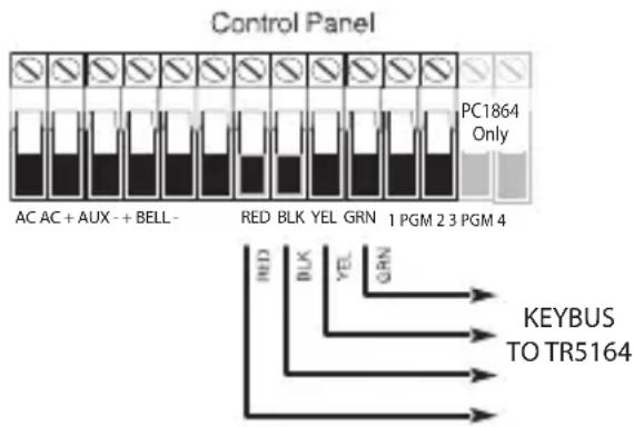
Figure 1
2.4 Receiver Placement Test
The TR5164 performs best in locations where RF interference is minimal. To find the best mounting location, perform the following placement test:
- Apply power to the TR5164 and hold it in the intended mounting location.
- If the yellow Trouble LED is on, interference levels are high and a new mounting location should be found. If the LED is flashing or off, interference is low and the location is good.
Enrollment consists of programming the device's Electronic Serial Number (ESN) into the TR5164 so it can be identified when an event is communicated. The ESN is located on the back of each device.
This section describes how to enroll and program:
- wireless devices using zones
- wireless keys
For more information, read the instruction sheet included with each device.
3.1 Enroll the Wireless Keypad On The TR5164
During initial power-up of the alarm panel, a 2-minute window is established for enrolling the wireless keypad (indicated by flashing red and green LEDs). If the enrollment window expires, power down the panel then power it up again. By default, WT5500 keypads are automatically assigned to slot numbers 8, 7, 6, 5.
To enroll a keypad:
- Power up the alarm system.
-
Power up the keypad. After a few seconds, "Hold [1] and [*] to Enroll Keypad" is displayed.
-
Press the [1] and [ *] keys together to enroll. "WFKP Enrollment Successful" is displayed.
If the “Failed to Enroll” message is displayed, perform the following:
- Retry the enrollment.
- Reposition the keypad closer to the control panel.
- Verify that the red and green indicators are flashing on the TR5164. If not, disconnect the panel from AC and DC power sources then reconnect.
- Check for RF interference. If the yellow LED is lit, RF traffic or noise floor level is too high.
NOTE: Set the zone definitions for wireless keypad slots as type 26 - 24Hr Non-Alarm.
3.2 Quick Enroll Wireless Devices/Keypads (WT5500 only)
- Enter [*][8][Installer Code][898]. "Wireless Enrollment Mode" is displayed.
-
Activate the device as indicated below.
-
Keypad: Press the [] and [1] keys at the same time.
- Wireless key: Press any key to activate.
- Detectors (PIR, Smoke, Glass break): Press the Tamper button.
-
Repeater: Press the Tamper button. Note: Ensure that dip switch 3 on the repeater is in the off position before quick enrolling a repeater.
-
The Electronic Serial Number (ESN) is displayed on the keypad. Press [*] to confirm the ESN. If the ESN is incorrect, press [#] then repeat step 2.
-
After successful confirmation of the ESN, t he system prompts for the zone/slot number.
-
The next open slot for the device type is displayed. Press [] to accept or key in another slot.
- To re-enroll a wireless key on another system, press 📄 together for 3 seconds.
3.3 Change Keypad Slot Assignment
To change the default slot number for a WT5500 keypad:
- Enter Installer Programming [ *][8][installer code].
- Enter section [804][000]. A 2-dig it field is displayed.
- In the first field, enter 1 for Partition 1 (only Partition 1 is supported). In the second field, enter a keypad slot number from 1-8 (e.g., 1,8 represents Partition 1, keypad slot 8).
-
Record the assigned slot number in the programming worksheets at the back of this manual.
-
After re-assigning a keypad, perform a supervisory reset by entering[*][8][Installer Code][902] and wait for 60 seconds.
-
Press [#] twice to exit after 60 seconds.
3.4 Manually Enroll Wireless Devices/Keypads
To manually enroll a 2-way wireless device:
-
Enter [*][8][Installer Code][804].
-
Enter the 3-digit zone/slot corr esponding to the device type:
| Wireless sensors, pendants, repeaters [804][001]-[064] (excluding [029]-[032]) |
| Wireless Key [804][101]-[116] for wireless key numbers 01-16 |
| Wireless Keypad [804][029]-[032] |
NOTE: Hardwired and wireless devices cannot be assigned to the same zone. PC5108 zone expander modules occupy zones in 2 groups of 4 (e.g., zones 9-12 and zones 13-16). None of the zones assigned to a PC5108 module may be used for wireless devices. For more information on zone assignment, consult the system installation manual.
A wireless key can only be assigned to one partition (partition 1 by default). To assign keys to a different partition, see “[804][183] Wireless Key (1-16) Partition Assignments” on page 20.
-
Enter the device serial number. On PK keypads, this is a 6-digit entry. When entering an 8-digit ESN, do not program the first two digits. On WT keypads, this is an 8-digit entry. When programming a 6-digit ESN, enter 00 for the first two digits. To toggle between decimal and hexadecimal values, press [*]. For instructions on programming hexadecimal numbers, see the system installation manual. The device is now enrolled on the system.
-
Record the serial number and the assigned zone number in the programming worksheets at the back of this manual.
-
Continue with steps 2 - 4 until all wireless devices are enrolled.
-
Press [#] to exit.
NOTE: Zone and partition programming must be completed for the wireless devices to operate correctly (see Section 4.1, page 8).
NOTE: (For non-UL listed installations) For Repeaters and Wireless Keypads, non-alarm zone type 26 is recommended. With this zone type, loss of AC or a Low battery condition are not reported to the central station. The alarm panel does not show a trouble for the zone but will indicate it as open. Select the Force Arm attribute for this zone. Program a zone label to identify the WS4920 or WT5500. E.g., "Rptr 1 Pwr Trbl."
NOTE: (For UL listed installations) If AC loss and low battery must be reported to the central station, use a 24-hour zone type. Ensure the Audible attribute is set to Silent.
To delete a wireless device:
- At a system keypad, enter [ *][8][Installer code][804].
- Enter the 3-digit number corresponding to the zone you want to remove the device from.
- Program the ESN as [00000000]. The device is deleted.
- Press [#] to exit.
Once all wireless devices are enrolled, program the system to work with the devices. See 4.1
"Program Zones and Partitions" on page 8 for more information.
4.1 Program Zones and Partitions
Once all wireless devices are enrolled, complete zone programming on the system. Ensure that the following programming options are completed correctly for each wireless zone:
- Enable zones and/or assign zones to one or more partitions (programming sections [202] to [265]).
- Program the definition for each zone (programming sections [001]-[004]).
- Enable the wireless zone attribute for each wireless zone (sections [101]-[164]).
Refer to the system installation manual for more information on the above programming sections.
4.2 Enable TR5164 Supervision
The control panel can supervise the TR5164 receiver via the Keybus after at least one device has been enrolled on the module (Section 3.1, page 6).
To activate module supervision:
-
Enroll the first device(s).
-
Exit and then re-enter Installer Programming, [*][8].
-
Enter programming section [902]. Wait approximately 60 seconds while the system scans for connected modules.
-
To exit press [#].
The system generates a General System Supervisory trouble if the module is removed from the Keybus. If the TR5164 module must be removed from an existing system, first disable TR5164 supervision.
NOTE: Deleting all devices from the TR5164 or defaulting the TR5164 causes a supervisory fault.
To disable TR5164 supervision:
- Disconnect the TR5164 from the Keybus.
- Enter [*][8][Installer Code].
- Enter [902]. The control panel clears all supervision and re-scans the system for connected modules. The scan takes approximately 60 seconds.
- To exit press [#].
To verify control panel supervision of the TR5164 (not available on WT5000 keypads):
-
Enter [*][8][Installer Code].
-
Enter [903] to display all modules. On an LED 32 zone keypad, light [17] indicates that the TR5164 is present on the system. On LCD keypads, scroll until the TR5164 module name is displayed.
-
To exit press [#].
If the TR5164 is not detected, check for one of the following problems:
- The module is not connected properly to the Keybus
• The Keybus wiring run is faulty - The module does not have enough power
- No devices have been enrolled on the TR5164
Interference
An RF Jam happens when an unwanted transmission from an outside source occurs in the receiver's area of operation that impedes the function of one or more devices.
The receiver is able to detect an RF jam condition and indicate an appropriate trouble to the control panel. This feature may be disabled in section [804][900], option [7].
4.3 Enable Supervision of Wireless Zones
Each wireless device (excluding wireless keys) sends a supervisory signal periodically. If the receiver does not receive a signal within the time programmed for the Wireless Supervisory Window, it generates a supervisory fault.
NOTE: For wireless supervision to work, enable the wireless zone attribute on all wireless zones (sections [101] to [164], option [8] ON).
To program the wireless supervisory window:
- Enter [*][8][Installer Code] to access Installer Programming.
- Enter [804] to access TR5164 Module Programming.
- Enter section [081].
-
Enter the time period for the supervisory window. The window is programmed in 15 minute increments. The default programming is:
-
96 (x15minutes), which is equal to 24 hours for the NA version, or
- 8 (x15minutes), which is equal to 2 hours for the EU version.
Valid entries are (4) to (96), equal to 1 to 24 hours.
- To exit press [#].
NOTE: Supervision must be enabled for RF Delinquency.
To disable/enable zone supervision:
- Enter [*][8][Installer Code] to access Installer Programming.
- Enter [804] to access TR5164 Module Programming.
- Enter sections [082]-[089]. Enable or disable supervision for each wireless zone by turning each relevant option on or off. Supervision is enabled by default for all wireless zones.
- To exit press [#].
4.4 Reporting Openings/Closings by Wireless Keys
Openings, closings and command output activation (e.g., opening a garage door) by individual wireless keys can generate a system report on certain control panels.
To enable reporting for wireless key openings/closings:
- Program a valid access code for each key (using [*][5] access code programming). NOTE: Program these access codes on the system after the TR5164 is connected to the Keybus (Section 2.4, page 5). Access codes 17 – 32 are reserved for wireless keys 01-16 respectively. Refer to the alarm panel installation manual for information on access code programming.
- Program an opening and closing reporting code for each key ([339]-[340], [342]-[343]).
- Turn off the Quick Arm option in section [015] option [4] of Installer Programming. NOTE: To ensure that an unidentified wireless key cannot disarm the system, turn off section [017], option [1] in Installer Programming.
4.5 Program Wireless Key Function Buttons
Wireless keys have four or six programmable function buttons. Default functions have been assigned, but other functions may be programmed if desired.
NOTE: 2-way wireless keys (WT4989) can only be assigned to partition 1. Wireless keys do not work when the partition is being programmed or bypassed.
To program wireless key function buttons:
- At a system keypad, enter [*][8][Installer Code].
- Enter programming section [804].
- Enter programming section [141] to [156] for wireless keys 1-16.
- For each of the available buttons on the wireless key, enter the 2-digit number corresponding to the selected function. See “Wireless Key Function Key Options” on page 18 for a list of function key options.
- Record all programming choices in the worksheets in the back of the manual.
- To exit press [#].
For more information on programming wireless key function buttons, refer to the wireless key installation sheet.
4.6 TR5164 Software Default
Returning the TR5164 programming to factory default settings removes all enrolled devices from the system and resets programming in section [804].
NOTE: Performing this procedure does not reset any other programming sections on the control panel. Likewise, resetting the control panel to factory defaults does not effect TR5164 programming.
To reset TR5164 programming to factory default settings:
- Enter [*][8] [Installer Code].
- Enter programming section [996].
- Enter the Installer Code, followed by [996] again. The software for the TR5164 is reset to factory defaults.
- To continue programming the unit, exit and then re-enter Installer Programming by pressing [#][*][8] [Installer Code].
For instructions on resetting the control panel or any other connected module to factory defaults, see the control panel installation manual.
5.1 Test the Reception of Wireless Devices
Testing the proposed placement of each wireless device before it is mounted is very important.
Following these steps tests the signal strength between the TR5164 and the wireless devices.
All wireless devices can be tested together (global placement testing) or individually.
NOTE: After the wireless devices are enrolled, Installer Programming must be exited and then re-entered at least once before performing a placement test.
To perform a global placement test:
-
Temporarily place the wireless devices in the preferred mounting locations.
-
At a system keypad, enter [*][8][Installer Code].
-
For WT5500 keypads, enter section [904] then key in [00]. In this mode, all wireless devices are placement tested at the same time.
-
For PK keypads, set section [804][900] option 8 to ON. Enter section [904] then key in the zone number of any wireless device.
-
Activate the device(s) as described in the e associated installation sheet. For two-way wireless keypads, press any key except the # key. The device name and zone number are displayed on the LCD.
Read the test results at the keypad:
| Result | LED Keypad | LCD Keypad | Buzzer/Bell |
| Good | Light 1 On Steady | “Good” | 1 Beep/Squawk |
| Bad | Light 3 On Steady | “Bad” | 3 Beeps/Squawks |
- Activate the device until three "good" results in a row are achieved.
- Mount the wireless devices where results are good. Devices indicating a bad result must be moved to another location. The device may only have to be moved a few inches to correct a bad result. Do not mount any device where a “bad” test result is indicated.
- Perform step 4 for each wireless device enrolled on the TR5164.
Wait until the placement test of one device is shown/sounded before testing the next one.
Continue to test the devices until both the TR5164 and the devices are in good locations. If several wireless devices produce “bad” test results, consider moving the TR5164 to a different location (see Section 2.2, page 5 for tips on finding a suitable location).
- To exit the placement test and return to Installer Programming, press [#] twice.
Testing Individual Devices
- Temporarily place the device in the preferred mounting location.
- At a system keypad, enter [ *][8][Installer Code].
- Enter programming section [904] for wireless devices. For PK keypads, ensure section [804][900] option 8 is OFF.
- Enter the 2-digit zone number f or the device.
- Activate the device until a result is displayed on the keypad or sounded by the keypad or bell.
- To test another device, press [#] once, then repeat steps 4 - 5. Continue to test the devices until both the TR5164 and the devices are in acceptable locations.
If several wireless devices produce “bad” test results, consider moving the TR5164 to a better location (see Section 2.2, page 5 for tips on finding a location for the TR5164).
- To exit the placement test and Installer Programming, press [#] twice.
Testing Individual Wireless Keys
Do not use the individual device test described above to test wireless keys. To ensure that the TR5164 is receiving transmissions from these devices, use the function keys on the wireless keys at several different points throughout the installation.
NOTE: Two-way wireless keys must be activated by pressing any key before they become functional.
5.2 Mounting
Once reception between the TR5164 and all wireless devices has been tested and verified (Section 5.1, page 11), mount as follows:
TR5164
- Pull the Keybus wires through the holes at the back of the cabinet or through the breakaway tabs at the sides.
- Mount the cabinet securely to the wall using the supplied 2 (two) screws. See Figure 2.
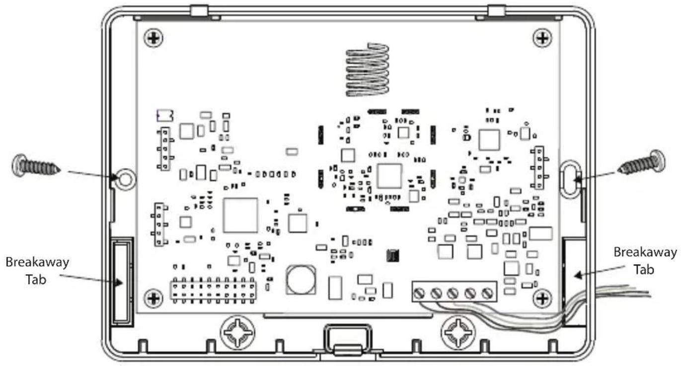
Figure 2
Wireless Devices
Mount the wireless devices once the placement test described in section 5.1 has been successfully completed and three “good” results in a row have been achieved for each device. See the installation sheet for each device for mounting instructions.
Now that the TR5164 and wireless devices are mounted and working properly, read Section 6.1, page 13, for information on potential wireless trouble conditions and battery replacement.
6.1 Trouble Conditions
The control panel constantly monitors for possible trouble conditions. If a trouble condition is detected, the keypad beeps and the “Trouble” light turns on. Press [*][2] to display trouble conditions.
The following trouble conditions apply to the TR5164 and/or any enrolled devices.
- RF Jam Detected (on Power panels v.2.01 and below) - This trouble is generated when the TR5164 detects an RF Jamming condition.
- Module Supervision- This trouble is generated if the panel loses communication with any module connected to the Keybus. The event buffer logs a detailed description of the event.
- Wireless Device Low Battery - This trouble is generated when a wireless device exhibits a low battery condition. Press [7] one, two, or three times to view which devices are experiencing battery failure. An LED keypad indicates battery failure using zone lights 1 to 8. See Section 6.2, page 13 for more information.
- Zone Tamper - This trouble is generated when an enrolled wireless device is removed from its mounting location.
- Zone Fault - Each wireless device sends a supervisory signal every 64 minutes (15 minutes for EU). If the receiver does not receive a signal within the time programmed for the Wireless Supervisory Window, a zone fault is generated.
- RF Delinquency (EU only) - Each wireless zone sends a supervisory signal every 15 minutes. If the receiver does not receive a signal within 15 minutes, an RF Delinquency trouble is generated for that zone.
NOTE: WT5500 keypad and wireless repeater AC and low battery troubles cause the corresponding zone to show as open on the alarm panel.
6.2 Wireless Zone Low Battery Transmission
The battery status of each device is regularly communicated to the alarm panel. If a battery is low, the system logs a Device Low Battery trouble.
The system delays reporting the event to the central station for the number of days programmed for Zone Low Battery Transmission Delay in section [377] of the panel. This prevents unnecessary reporting of the event if the user has been instructed on how to replace batteries.
Replacing Batteries in Wireless Devices
- Refer to the battery installation instructions on the installation sheet of each device. Be sure to observe correct polarity when installing new batteries.
-
When the new batteries are in place and the tamper is restored, the battery trouble is cleared and the device should function normally.
-
When I enter the 3-digit zone number for adding a wireless device, the keypad gives me a long beep.
ESNs can be entered only when a TR5164 wireless receiver is connected to the Keybus. See Section 2.3, page 5 for instructions on setting up and wiring the TR5164 module.
- I have entered the ESN for the device but when I activate it, the zone does not show open on the keypad.
Check the following:
- Ensure the ESN has been entered correctly.
- Ensure that the zone is enabled for the partition (if partition programming is used).
- Ensure that the wireless zone is not assigned to a zone used by PC5108 modules, an on-board zone, or a keypad zone.
-
Ensure that the zone is programmed for something other than “Null Operation,” and that the Wireless Zone attribute is turned on.
-
When I try a module placement test I get no result or "bad" results.
Check the following (see Section 5.1, page 11 for more information on testing devices):
- Verify that the correct zone is being tested.
- Verify that the correct ESN was entered when the device was enrolled.
- Verify that the device is in range of the TR5164. Try testing the device in the same room as the receiver.
- Confirm that the TR5164 is properly connected to the Keybus (see Section 2.4, page 5 for TR5164 set up and wiring instructions).
- Check that the zone is being tested correctly (see Section 5.1, page 11 for testing instructions).
- Check that the batteries are working and installed correctly.
-
Look for large metal objects that may be preventing the signal from reaching the TR5164.
The device must be located where consistent “good” results are obtained. If several devices show “bad” results, move the receiver. See Section 2.2, page 5 for tips on choosing a mounting location for the TR5164. -
The LED on the motion detector does not turn on when I walk in front of the unit.
The LED is for walk test purposes only. See the Wireless PIR Instruction Sheet for walk test instructions.
TR5164 Wireless Programming
Use the following worksheets to record wireless device programming options for future reference. NA= default value for North America; EU= default value for Europe
[804][000] Wireless Keypad Partition and Slot Programming
Keypad Default
| WT5500 #1 1,8 |
| WT5500 #2 1,7 |
| WT5500 #3 1,6 |
| WT5500 #4 1,5 |
NOTE: The first digit represents the partition (only partition 1 is supported). The second digit is the keypad slot number. (e.g., 1,8 = partition 1, slot 8) Wireless keypads can be programmed into slots 1-8. Default slots are 8,7,6,5.
[804][001]-[064] Wireless Zone Programming (for wireless devices, repeaters and keypads)
Wireless keypads 1-4 must be enrolled into zones 29-32 respectively. All other wireless devices may be enrolled into any of the remaining 60 zones.
Default = 00000000
Zone Zone
| [001] [0,12] | ||||||||
| [002] [0,13] | ||||||||
| [003] [0,14] | ||||||||
| [004] [0,15] | ||||||||
| [005] [0,16] | ||||||||
| [006] [0,17] | ||||||||
| [007] [0,18] | ||||||||
| [008] [0,19] | ||||||||
| [009] [0,20] | ||||||||
| [010] [0,21] | ||||||||
| [011] [0,22] |
Zone Zone
The window is programmed in 15 minute increments.
The default programming is:
- 96 (x15minutes), which is equal to 24 hours (NA), or
- 8 (x15minutes), which is equal to 2 hours (EU).
Valid entries are (004) to (096), equal to 1 to 24 hours.
NOTE:
[804][082]-[089] Zone Transmitter Supervision Options
| [082] Zone 1-8 [083] | Zones9-16 | [084] Zones17-24 | [085] Zones25-32 | ||||
| Opt Def. Def. Def. | |||||||
| 1 | √ □ Zone 1 | √ □ | Zone 9 | √ □ | Zone 17 | √ □ | Zone 25 |
| 2 | Zone√2 Zone 10 Zone 18 | Zone 26 | √ □ | √ □ | |||
| 3 | √ □ Zone 3 | √ □ | Zone 11 | √ □ | Zone 19 | √ □ | Zone 27 |
| 4 | Zone√4 Zone 12 Zone 20 | Zone 28 | √ □ | √ □ | |||
| 5 | Zone√5 Zone 13 Zone 21 | Zone 29 | √ □ | √ □ | |||
| 6 | Zone√6 Zone 14 Zone 22 | Zone 30 | √ □ | √ □ | |||
| 7 | Zone√7 Zone 15 Zone 23 | Zone 3□ | √ □ | √ □ | |||
| 8 | Zone√8 Zone 16 Zone 24 | Zone 32 | √ □ | √ □ | |||
| [086] | Zone33-40 | [087] Zones41-48 | [088] Zones49-56 | [089] Zones57-64 | |||
| Opt Def. Def. Def. | |||||||
| 1 | Zone√33 □ | Zone√41 Zone 49 Zone 57 | √ □ | √ □ | |||
| 2 | Zone√34 □ | Zone√42 Zone 50 Zone 58 | √ □ | √ □ | |||
| 3 | Zone√35 □ | Zone√43 Zone 51 Zone 59 | √ □ | √ □ | |||
| 4 | Zone√36 □ | Zone√44 Zone 52 Zone 60 | √ □ | √ □ | |||
| 5 | Zone√37 □ | Zone√45 Zone 53 Zone 61 | √ □ | √ □ | |||
| 6 | Zone√38 □ | Zone√46 Zone 54 Zone 62 | √ □ | √ □ | |||
| 7 | Zone√39 □ | Zone√47 Zone 55 Zone 63 | √ □ | √ □ | |||
| 8 | Zone√40 □ | Zone√48 Zone 56 Zone 64 | √ □ | √ □ | |||
NOTE: Panic transmitters are NOT supervised and must be disabled in this section.
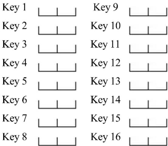
[804][101]-[116] Wireless Key Serial Numbers
| [101] [109] | |
| [102] [110] | |
| [103] [111] | |
| [104] [112] | |
| [105] [113] | |
| [106] [114] | |
| [107] [115] | |
| [108] [116] |
Wireless Key Function Key Options
| Entry Key Description Entry Key Description | |||
| 00 Null Key 18 Global Away Arm | |||
| 01-02 | Future Use | 19 | [*][7][3] Command Output #3 |
| 03 Stay Arm 20 Future Use | |||
| 04 | Away Arm | 21 | [*][7][4] Command Output #4 |
| 05 | [*][9] No-Entry Arm | 22 | Global Disarm |
| 06 | [*][4] Chime ON/OFF | 23-26 | Future Use |
| 7-12 | Future Use 27 Disarm (OFF) | ||
| 13 | [*][7][1] Command Output #1 | 28 | Future Use |
| 14 | [*][7][2] Command Output #2 | 29 | Auxiliary Alarm |
| 15 | Global Stay Arm | 30 | Panic Alarm |
| 16 | [*][0] Quick Exit | 31-33 | Future Use |
| 17 [*][1] Activate Stay/Away | |||
| NOTE: Wireless keys must have an access code for global arm/global disarm functions. | |||
[804][141]-[156] Wireless Function Key Options
| Function 1Default 0,3 | Function 2Default 0,4 | Function 3Default 2,7 | Function 4Default 3,0 | Function 5Default 1,3 | Function 6Default 1,4 | |
| [141] Key 1 | ||||||
| [142] Key 2 | ||||||
| [143] Key 3 | ||||||
| [144] Key 4 | ||||||
| [145] Key 5 | ||||||
| [146] Key 6 | ||||||
| [147] Key 7 | ||||||
| [148] Key 8 | ||||||
| [149] Key 9 | ||||||
| [150] Key 10 | ||||||
| [151] Key 11 | ||||||
| [152] Key 12 | ||||||
| [153] Key 13 | ||||||
| [154] Key 14 | ||||||
| [155] Key 15 | ||||||
| [156] Key 16 |
NOTE: Functions 5 and 6 are for WT4989 only.
[804][181]-[182] Enable/Disable 2-Way Wireless Keys 1-16
| [804][181] Enable/Disable 2-Way Wireless Keys 1-8 | [804][182] Enable/Disable 2-Way Wireless Keys 9-16 | |||||||||
| Opt | Def | ON | OFF | Opt | Def | ON | OFF | |||
| 1 | Off | ☐ | Key 1 is 2-way | Key 1 is 1-way | 1 | Off | ☐ | Key 9 is 2-way | Key 9 is 1-way | |
| 2 | Off | ☐ | Key 2 is 2-way | Key 2 is 1-way | 2 | Off | ☐ | Key 10 is 2-way | Key 10 is 1-way | |
| 3 | Off | ☐ | Key 3 is 2-way | Key 3 is 1-way | 3 | Off | ☐ | Key 11 is 2-way | Key 11 is 1-way | |
| 4 | Off | ☐ | Key 4 is 2-way | Key 4 is 1-way | 4 | Off | ☐ | Key 12 is 2-way | Key 12 is 1-way | |
| 5 | Off | ☐ | Key 5 is 2-way | Key 5 is 1-way | 5 | Off | ☐ | Key 13 is 2-way | Key 13 is 1-way | |
| 6 | Off | ☐ | Key 6 is 2-way | Key 6 is 1-way | 6 | Off | ☐ | Key 14 is 2-way | Key 14 is 1-way | |
| 7 | Off | ☐ | Key 7 is 2-way | Key 7 is 1-way | 7 | Off | ☐ | Key 15 is 2-way | Key 15 is 1-way | |
| 8 | Off | ☐ | Key 8 is 2-way | Key 8 is 1-way | 8 | Off | ☐ | Key 16 is 2-way | Key 16 is 1-way | |
[804][183] Wireless Key (1-16) Partition Assignments
(Default = 01)
[804][800] Keypad Miscellaneous Options
| Option | Default | Option ON | Option OFF |
| 1 | On | ☐ Chime on Openings Enabled | ☐ Chime on Openings Disabled |
| 2 Off | ☐ Chime on Closings Enabled | ☐ Chime on Closings Disabled | |
| 3-8 | Off | ☐ Future Use | ☐ |
[804][801] - [864] Custom Door Chime Programming (for zones 1-64)
Opt Default Description
1 On 6 Beeps□
2 Off "Bing-Bing" sound
3 Off "Ding-Dong" sound
4 Off Alarm Tone
5-8 Off Future Use
[801] [815] [829] [843] [857] 1 2 3 4 1 2 3 4 1 2 3 4 1 2 3 4 1 2 3 4
[802] [816] [830] [844] [858] 1 2 3 4 1 2 3 4 1 2 3 4 1 2 3 4 1 2 3 4
[803] [817] [831] [845] [859] 1 2 3 4 1 2 3 4 1 2 3 4 1 2 3 4 1 2 3 4
[804] [818] [832] [846] [860] 1 2 3 4 1 2 3 4 1 2 3 4 1 2 3 4 1 2 3 4
[805] [819] [833] [847] [861] 1 2 3 4 1 2 3 4 1 2 3 4 1 2 3 4 1 2 3 4
[806] [820] 1 2 3 4 1 2 3 4 1 2 3 4 1 2 3 4 1 2 3 4 [834
[807] [821] [835] [849] [863] 1 2 3 4 1 2 3 4 1 2 3 4 1 2 3 4 1 2 3 4
[808] [822] [836] [850] [864] 1 2 3 4 1 2 3 4 1 2 3 4 1 2 3 4 1 2 3 4
[809] [823] [837] [851]
1 2 3 4 1 2 3 4 1 2 3 4 1 2 3 4
[810] [824] [838] [852]
1 2 3 4 1 2 3 4 1 2 3 4 1 2 3 4
[811] [825] [839] [853]
1 2 3 4 1 2 3 4 1 2 3 4 1 2 3 4
[812] [826] [840] [854]
1 2 3 4 1 2 3 4 1 2 3 4 1 2 3 4
[813] [827] [841] [855]
1 2 3 4 1 2 3 4 1 2 3 4 1 2 3 4
[814] [828] [842] [856]
1 2 3 4 1 2 3 4 1 2 3 4 1 2 3 4
[804][900] General Wireless Options
| Option | Default Option ON Option OFF | |||
| NA EU | ||||
| 1-2 Off Off □ | Future Use □ Future Use | |||
| 3 | On | Off | □ Wall Tamper Disabled | □ Wall Tamper Enabled |
| 4 | Off | Off | □ Case Tamper Disabled | □ Case Tamper Enabled |
| 5 | On | Off | □ Wireless Delinquency Disabled | □ Wireless Delinquency Enabled |
| 6 | Off | Off | □ Future Use | □ Future Use |
| 7 | On | Off | □ RF Jam Disabled | □ RF Jam Enabled |
| 8 Off Off □ | Global Placement Test (PK keypads only) | □ Individual Placement Test | ||
NOTE: For UL Listed installations, the RF Jam feature must be enabled - [804][900] option 7 OFF.
[904] Wireless Device Placement Test
8.1 See "Testing Individual Devices" on page 11 for details.
[996] Restore Labels to Factory Default
Entering this section and pressing [*] returns all programmable system labels to their default settings in the currently active language. Keypad configuration sections are not affected.
Limited Warranty
Digital Security Controls warrants the original purchaser that for a period of twelve months from the date of purchase, the product shall be free of defects in materials and workmanship under normal use. During the warranty period, Digital Security Controls shall, at its option, repair or replace any defect vc product upon return of the product to its factory, at no charge for labour and materials. Any replacement and/or repaired parts are warranted for the remainder of the original warranty or ninety (90) days, whichever is longer. The original purchaser must promptly notify Digital Security Controls in writing that there is defect in material or workmanship, such written notice to be received in all events prior to expiration of the warranty period. There is absolutely no warranty on software and all software products are sold as a user license under the terms of the software license agreement included with the product. The Customer assumes all responsibility for the proper selection, installation, operation and maintenance of any products purchased from DSC. Custom products are only warranted to the extent that they do not function upon delivery. In such cases, DSC can replace or credit at its option.
International Warranty
The warranty for international customers is the same as for any customer within Canada and the United States, with the exception that Digital Security Controls shall not be responsible for any customs fees, taxes, or VAT that may be due.
Warranty Procedure
To obtain service under this warranty, please return the items) in question to the point of purchase. All authorized distributors and dealers have a warranty program. Anyone returning goods to Digital Security Controls must first obtain an authorization number. Digital Security Controls will not accept any shipment whatsoever for which prior authorization has not been obtained.
Conditions to Void Warranty
This warranty applies only to defects in parts and workmanship relating to normal use. It does not cover:
• damage incurred in shipping or handling;
• damage caused by disaster such as fire, flood, wind, earthquake or lightning;
- damage due to causes beyond the control of Digital Security Controls such as excessive voltage, mechanical shock or water damage;
- damage caused by unauthorized attachment, alterations, modifications or foreign objects;
- damage caused by peripherals (unless such peripherals were supplied by Digital Security Controls);
• defects caused by failure to provide a suitable installation environment for the products;
- damage caused by use of the products for purposes other than those for which it was designed;
• damage from improper maintenance;
- damage arising out of any other abuse, mishandling or improper application of the products.
Items Not Covered by Warranty
In addition to the items which void the Warranty, the following items shall not be covered by Warranty: (i) freight cost to the repair centre; (ii) products which are not identified with DSC's product label and lot number or serial number; (iii) products disassembled or repaired in such a manner as to adversely affect performance or prevent adequate inspection or testing to verify any warranty claim. Access cards or tags returned for replacement under warranty will be credited or replaced at DSC's option. Products not covered by this warranty, or otherwise out of warranty due to age, misuse, or damage shall be evaluated, and a repair estimate shall be provided. No repair work will be performed until a valid purchase order is received from the Customer and a Return Merchandise Authorisation number (RMA) is issued by DSC's Customer Service.
Digital Security Controls's liability for failure to repair the product under this warranty after a reasonable number of attempts will be limited to a replacement of the product, as the exclusive remedy for breach of warranty. Under no circumstances shall Digital Security Controls be liable for any special, incidental, or consequential damages based upon breach of warranty, breach of contract, negligence, strict liability, or any other legal theory. Such damages include, but are not limited to, loss of profits, loss of the product or any associated equipment, cost of capital, cost of substitute or replacement equipment, facilities or services, down time, purchaser's time, the claims of third parties, including customers, and injury to property. The laws of some jurisdictions limit or do not allow the disclaimer of consequential damages. If the laws of such a jurisdiction apply to any claim by or against DSC, the limitations and disclaimers contained here shall be to the greatest extent permitted by law. Some states do not allow the exclusion or limitation of incidental or consequential damages, so that the above may not apply to you.
Disclaimer of Warranties
This warranty contains the entire warranty and shall be in lieu of any and all other warranties, whether expressed or implied (including all implied warranties of merchantability or fitness for a particular purpose) and of all other obligations or liabilities on the part of Digital Security Controls. Digital Security Controls neither assumes responsibility for nor authorizes any other person purporting to act on its behalf to modify or to change this warranty, nor to assume for it any other warranty or liability concerning this product.
This disclaimer of warranties and limited warranty are governed by the laws of the province of Ontario, Canada.
WARNING: Digital Security Controls recommends that the entire system be completely tested on a regular basis. However, despite frequent testing, and due to, but not limited to, criminal tampering or electrical disruption, it is possible for this product to fail to perform as expected.
Out of Warranty Repairs
Digital Security Controls will at its option repair or replace out-of-warranty products which are returned to its factory according to the following conditions. Anyone returning goods to Digital Security Controls must first obtain an authorization number. Digital Security Controls will not accept any shipment whatsoever for which prior authorization has not been obtained.
Products which Digital Security Controls determines to be repairable will be repaired and returned. A set fee which Digital Security Controls has predetermined and which may be revised from time to time, will be charged for each unit repaired.
Section 1: Introduction......26
Section 5: Essai et installation ....35
5.1 Test de réception du dispositif sans fil 35
5.2 Installation ....36
Section 6: Remarques supplémentaires .....38
6.1 Situations de trouble ....38
6.2 Pile basse zone sans fil .....38
Section 7: Diagnostic de pannes ......39
Section 8: Feuilles de programmation .....40
Section 9: Español....49
Section 10: Portugais....73
UL985 Household Fire Warning System Units
UL1023 Household Burglar-Alarm System Units
UL1610 Central Station Burglar-Alarm Units
Section 1: Introduction
□□□□
□□□□
□□□□
□□□□
□□□□
□□□□
□□□□
□□□□
□□□□
□□□□
□□□□
□□□□
□□□□
□□□□
□□□□
[848][862]
The image contains three identical rectangular blocks, each containing four empty squares. There is no text or symbols present in the image.
□□□□
□□□□
□□□□
□□□□
□□□□
□□□□
□□□□
□□□□
□□□□
□□□□
□□□□
□□□□
□□□□
□□□□
□□□□
2 Off Som "bing-bing"
3 Off Som "ding-dong"
4 Off Tonalidade de alarme
5-8 Off Uso futurb
[801] [815] [829] [843] [857] 1 2 3 4 1 2 3 4 1 2 3 4 1 2 3 4 1 2 3 4
[802] [816] [830] [844] [858] 1 2 3 4 1 2 3 4 1 2 3 4 1 2 3 4 1 2 3 4
[803] [817] [831] [845] [859] 1 2 3 4 1 2 3 4 1 2 3 4 1 2 3 4 1 2 3 4
[804] [818] [832] [846] [860] 1 2 3 4 1 2 3 4 1 2 3 4 1 2 3 4 1 2 3 4
[805] [819] [833] [847] [861] 1 2 3 4 1 2 3 4 1 2 3 4 1 2 3 4 1 2 3 4
[806] [820] [834] [848] [862] 1 2 3 4 1 2 3 4 1 2 3 4 1 2 3 4 1 2 3 4
[807] [821][835][849][863] 1 2 3 4 1 2 3 4 1 2 3 4 1 2 3 4 1 2 3 4
[808] [822] [836] [850] [864] 1 2 3 4 1 2 3 4 1 2 3 4 1 2 3 4 1 2 3 4
[809] [823] [837] [851] 1 2 3 4 1 2 3 4 1 2 3 4 1 2 3 4
[810] [824] [838] [852] 1 2 3 4 1 2 3 4 1 2 3 4 1 2 3 4
[811] [825] [839] [853] 1 2 3 4 1 2 3 4 1 2 3 4 1 2 3 4
[812] [826] [840] [854] 1 2 3 4 1 2 3 4 1 2 3 4 1 2 3 4
[813] [827] [841] [855] 1 2 3 4 1 2 3 4 1 2 3 4 1 2 3 4
[814] [828] [842] [856] 1 2 3 4 1 2 3 4 1 2 3 4 1 2 3 4
□□□□ □□□□ □□□□
□□□□ □□□□ □□□□
□□□□ □□□□ □□□□
□□□□ □□□□ □□□□
□□□□ □□□□ □□□□
□□□□ □□□□ □□□□
□□□□ □□□□ □□□□
□□□□ □□□□ □□□□
□□□□ □□□□
□□□□ □□□□
□□□□ □□□□
□□□□ □□□□
□□□□ □□□□
□□□□ □□□□
FCC Compliance Statement
CAUTION: Changes or modifications not expressly approved by Digital Security Controls could void your authority to use this equipment.
This equipment generates and uses radio frequency energy and if not installed and used properly, in strict accordance with the manufacturer's instructions, may cause interference to radio and television reception. It has been type tested and found to comply with the limits for Class B device in accordance with the specifications in Subpart "B" of Part 15 of FCC Rules, which are designed to provide reasonable protection against such interference in any residential installation. However, there is no guarantee that interference will not occur in a particular installation. If this equipment does cause interference to television or radio reception, which can be determined by turning the equipment off and on, the user is encouraged to try to correct the interference by one or more of the following measures:
•Re-orient the receiving antenna
- Relocate the alarm control with respect to the receiver
- Move the alarm control away from the receiver
- Connect the alarm control into a different outlet so the alarm control & receiver are on different circuits.
Hereby, DSC, declares that this device is in compliance with the essential requirements and other relevant provisions of Directive 1999/5/EC. The complete R&TTE Declaration of Conformity can be found at http://www.dsc.com/listings_index.aspx
(CZE) DSC jako výrobce prohlašuje, že tento výrobek je v souladu se všemi relevantními požadavky směmice 1999/5/EC.
(DAN) DSC erklærer herved at denne komponenten overholder alle viktige krav samt andre bestemmelser gitt i direktiv 1999/5/EC.
(DUT) Hierbij verklaart DSC dat dit toestel in overeenstemming is bepalingen van richtlijn 1999/5/EC.
(FIN) DSC vakuuttaa laitteen täyttävän direktiivin 1999/5/EC olennaiset vaatimukset. (FRE) Par la présente, DSC déclare que ce dispositif est cont essentielles et autres stipulations pertinentes de la Directive 1999/5/EC.
(GER) Hierdurch erklärt DSC, daß dieses Gerät den erforderlichen Bedingungen und Vorrausetzungen der Richtlinie 1999/5/EC entspricht.
(GRE) Dia tou paróvtoç, η DSC, δηλύνει όπ αυτή η συσκευή είναι σύμφωνη με τις ουσιώδης απαιτήσει και με όλες τις άλλες σχετικές αναφορές της Οδηγίας 1999/5/EC.
(ITA) Con la presente la Digital Security Controls dichiara che questo prodotto conforme ai requisiti essenziali ed altre disposizioni rilevanti relative alla Direttiva 1999/05/CE.
(NOR) DSC erklærer at denne enheten er i samsvar med de grunnleggende krav og øvrige relevante krav i direktiv 1999/5/EF.
(POL) DSC oświadcza, że urządzenie jest w zgodności z zasadniczymi wymaganiami oraz pozostałymi stosownymi postanowieniami Dyrektywy 1999/5/WE.
(POR) Por este meio, a DSC, declara que este equipamento está em conformidade com os requisitos essenciais e outras determinações relevantes da Directiva 1999/5/EC.
(SPA) Por la presente, DSC, declara que este equipo está en conformidad con los requisitos esenciales y otros requisitos relevantes de la Directiva 1999/5/EC.
(SWE) DSC bekräftar hämed att denna apparat uppfyller de väsentliga kraven och andra relevanta bestämmelser i Direktivet 1999/5/EC.
If necessary, the user should consult the dealer or an experienced radio/television technician for additional suggestions. The user may find the following booklet prepared by the FCC helpful: "How to Identify and Resolve Radio/Television Interference Problems". This booklet is available from the U.S. Government Printing Office, Washington, D.C. 20402, Stock # 004-000-00345-4.
The term ‘IC:’ before the radio certification number only signifies that Industry Canada technical specifications were met.
© 2012 Tyco International Ltd. and its Respective Companies. All Rights Reserved.
Toronto, Canada • www.dsc.com
Tech. Support/Centre d'aide technique/Líneas Tech: 1-800-387-3630 (Canada, US), 905-760-3000
Printed in Canada / Imprimé au Canada / Impreso en Canadá / Impresso no Canadá


29008363R001