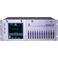
SG-System III - Receiver DSC - Free user manual and instructions
Find the device manual for free SG-System III DSC in PDF.


| Product Type | Receiver |
| Brand | DSC |
| Model | SG-System III |
| Dimensions (mm) | 200 x 150 x 50 |
| Weight (kg) | 0.5 |
| Power Supply | 12V DC |
| Operating Frequency | 433 MHz |
| Compatible Devices | DSC wireless sensors |
| Number of Zones | 8 |
| LED Indicators | Power, Signal, Tamper |
| Mounting | Wall mount |
| Operating Temperature | -10°C to 50°C |
| Humidity Range | 5% - 95% |
| Housing Material | Plastic |
| Color | White |
| Certifications | FCC, CE |
| Warranty | 2 years |
| Care Instructions | Clean with dry cloth |
| Safety Precautions | Avoid exposure to moisture |
Frequently Asked Questions - SG-System III DSC
User questions about SG-System III DSC
0 question about this device. Answer the ones you know or ask your own.
Ask a new question about this device
Download the instructions for your Receiver in PDF format for free! Find your manual SG-System III - DSC and take your electronic device back in hand. On this page are published all the documents necessary for the use of your device. SG-System III by DSC.
USER MANUAL SG-System III DSC
SG-System III
Operating Manual




version 2.0
NOTE: This manual contains information regarding product use and function, in addition to manufacturer liability and restrictions pertaining to it. The entire manual should be read carefully.
WARNING Please Read Carefully
Note to Installers
This warning contains vital information. As the only individual in contact with system users, it is your responsibility to bring each item in this warning to the attention of the users of this system.
System Failures
This system has been carefully designed to be as effective as possible. There are circumstances, however, involving fire, burglary, or other types of emergencies where it may not provide protection. Any alarm system of any type may be compromised deliberately or may fail to operate as expected for a variety of reasons. Some but not all of these reasons may be:
• Inadequate Installation
A security system must be installed properly in order to provide adequate protection. Every installation should be evaluated by a security professional to ensure that all access points and areas are covered. Locks and latches on windows and doors must be secure and operate as intended. Windows, doors, walls, ceilings and other building materials must be of sufficient strength and construction to provide the level of protection expected. A revaluation must be done during and after any construction activity. An evaluation by the fire and/or police department is highly recommended if this service is available.
• Criminal Knowledge
This system contains security features which were known to be effective at the time of manufacture. It is possible for persons with criminal intent to develop techniques which reduce the effectiveness of these features. It is important that a security system be reviewed periodically to ensure that its features remain effective and that it be updated or replaced if it is found that it does not provide the protection expected.
- Access by Intruders
Intruders may enter through an unprotected access point, circumvent a sensing device, evade detection by moving through an area of insufficient coverage, disconnect a warning device, or interfere with or prevent the proper operation of the system.
• Power Failure
Control units, intrusion detectors, smoke detectors and many other security devices require an adequate power supply for proper operation. If a device operates from batteries, it is possible for the batteries to fail. Even if the batteries have not failed, they must be charged, in good condition and installed correctly. If a device operates only by AC power, any interruption, however brief, will render that device inoperative while it does not have power. Power interruptions of any length are often accompanied by voltage fluctuations which may damage electronic equipment such as a security system. After a power interruption has occurred, immediately conduct a complete system test to ensure that the system operates as intended.
• Failure of Replaccable Batteries
This system's wireless transmitters have been designed to provide several years of battery life under normal conditions. The expected battery life is a function of the device environment, usage and type. Ambient conditions such as high humidity, high or low temperatures, or large temperature fluctuations may reduce the expected battery life. While each transmitting device has a low battery monitor which identifies when the batteries need to be replaced, this monitor may fail to operate as expected. Regular testing and maintenance will keep the system in good operating condition.
• Compromise of Radio Frequency (Wireless) Devices
Signals may not reach the receiver under all circumstances which could include metal objects placed on or near the radio path or deliberate jamming or other inadvertent radio signal interference.
- System Users
A user may not be able to operate a panic or emergency switch possibly due to permanent or temporary physical disability, inability to reach the device in time, or unfamiliarity with the correct operation. It is important that all system users be trained in the correct operation of the alarm system and that they know how to respond when the system indicates an alarm.
• Smoke Detectors
Smoke detectors that are a part of this system may not properly alert occupants of a fire for a number of reasons, some of which follow. The smoke detectors may have been improperly installed or positioned. Smoke may not be able to reach the smoke detectors, such as when the fire is in a chimney, walls or roofs, or on the other side of closed doors. Smoke detectors may not detect smoke from fires on another level of the residence or building.
Every fire is different in the amount of smoke produced and the rate of burning. Smoke detectors cannot sense all types of fires equally well. Smoke detectors may not provide timely warning of fires caused by carelessness or safety hazards such as smoking in bed, violent explosions, escaping gas, improper storage of flammable materials, overloaded electrical circuits, children playing with matches or arson.
Even if the smoke detector operates as intended, there may be circumstances when there is insufficient warning to allow all occupants to escape in time to avoid injury or death.
- Motion Detectors
Motion detectors can only detect motion within the designated areas as shown in their respective installation instructions. They cannot discriminate between intruders and intended occupants. Motion detectors do not provide volumetric area protection. They have multiple beams of detection and motion can only be detected in unobstructed areas covered by these beams. They cannot detect motion which occurs behind walls, ceilings, floor, closed doors, glass partitions, glass doors or windows. Any type of tampering whether intentional or unintentional such as masking, painting, or spraying of any material on the lenses, mirrors, windows or any other part of the detection system will impair its proper operation.
Passive infrared motion detectors operate by sensing changes in temperature. However their effectiveness can be reduced when the ambient temperature rises near or above body temperature or if there are intentional or unintentional sources of heat in or near the detection area. Some of these heat sources could be heaters, radiators, stoves, barbeques, fireplaces, sunlight, steam vents, lighting and so on.
- Warning Devices
Warning devices such as sircns, bells, horns, or strobes may not warn people or waken someone sleeping if there is an intervening wall or door. If warning devices are located on a different level of the residence or premise, then it is less likely that the occupants will be alerted or awakened. Audible warning devices may be interfered with by other noise sources such as stereos, radios, televisions, air conditioners or other appliances, or passing traffic. Audible warning devices, however loud, may not be heard by a hearing-impaired person.
- Telephone Lines
If telephone lines are used to transmit alarms, they may be out of service or busy for certain periods of time. Also an intruder may cut the telephone line or defeat its operation by more sophisticated means which may be difficult to detect.
- Insufficient Time
There may be circumstances when the system will operate as intended, yet the occupants will not be protected from the emergency due to their inability to respond to the warnings in a timely manner. If the system is monitored, the response may not occur in time to protect the occupants or their belongings.
- Component Failure
Although every effort has been made to make this system as reliable as possible, the system may fail to function as intended due to the failure of a component.
• Inadequate Testing
Most problems that would prevent an alarm system from operating as intended can be found by regular testing and maintenance. The complete system should be tested weekly and immediately after a break-in, an attempted break-in, a fire, a storm, an earthquake, an accident, or any kind of construction activity inside or outside the premises. The testing should include all sensing devices, keypads, consoles, alarm indicating devices and any other operational devices that are part of the system.
• Security and Insurance
Regardless of its capabilities, an alarm system is not a substitute for property or life insurance. An alarm system also is not a substitute for property owners, renters, or other occupants to act prudently to prevent or minimize the harmful effects of an emergency situation.
Limited Warranty
Digital Security Controls warrants the original purchaser that for a period of twelve months from the date of purchase, the product shall be free of defects in materials and workmanship under normal use. During the warranty period, Digital Security Controls shall, at its option, repair or replace any defective product upon return of the product to its factory, at no charge for labour and materials. Any replacement and/or repaired parts are warranted for the remainder of the original warranty or ninety (90) days, whichever is longer. The original purchaser must promptly notify Digital Security Controls in writing that there is defect in material or workmanship, such written notice to be received in all events prior to expiration of the warranty period. There is absolutely no warranty on software and all software products are sold as a user license under the terms of the software license agreement included with the product. The Customer assumes all responsibility for the proper selection, installation, operation and maintenance of any products purchased from DSC. Custom products are only warranted to the extent that they do not function upon delivery. In such cases, DSC can replace or credit at its option.
International Warranty
The warranty for international customers is the same as for any customer within Canada and the United States, with the exception that Digital Security Controls shall not be responsible for any customs fees, taxes, or VAT that may be due.
Warranty Procedure
To obtain service under this warranty, please return the item(s) in question to the point of purchase. All authorized distributors and dealers have a warranty program. Anyone returning goods to Digital Security Controls must first obtain an authorization number. Digital Security Controls will not accept any shipment whatsoever for which prior authorization has not been obtained.
Conditions to Void Warranty
This warranty applies only to defects in parts and workmanship relating to normal use. It does not cover:
• damage incurred in shipping or handling;
- damage caused by disaster such as fire, flood, wind, earthquake or lightning;
- damage due to causes beyond the control of Digital Security Controls such as excessive voltage, mechanical shock or water damage;
- damage caused by unauthorized attachment, alterations, modifications or foreign objects;
- damage caused by peripherals (unless such peripherals were supplied by Digital Security Controls);
- defects caused by failure to provide a suitable installation environment for the products;
- damage caused by use of the products for purposes other than those for which it was designed;
• damage from improper maintenance;
- damage arising out of any other abuse, mishandling or improper application of the products.
Items Not Covered by Warranty
In addition to the items which void the Warranty, the following items shall not be covered by Warranty: (i) freight cost to the repair centre; (ii) products which are not identified with DSC's product label and lot number or serial number; (iii) products disassembled or repaired in such a manner as to adversely affect performance or prevent adequate inspection or testing to verify any warranty claim. Access cards or tags returned for replacement under warranty will be credited or replaced at DSC's option. Products not covered by this warranty, or otherwise out of warranty due to age, misuse, or damage shall be evaluated, and a repair estimate shall be provided. No repair work will be performed until a valid purchase order is received from the Customer and a Return Merchandise Authorisation number (RMA) is issued by DSC's Customer Service.
Digital Security Controls's liability for failure to repair the product under this warranty after a reasonable number of attempts will be limited to a replacement of the product, as the exclusive remedy for breach of warranty. Under no circumstances shall Digital Security Controls be liable for any special, incidental, or consequential damages based upon breach of warranty, breach of contract, negligence, strict liability, or any other legal theory. Such damages include, but are not limited to, loss of profits, loss of the product or any associated equipment, cost of capital, cost of substitute or replacement equipment, facilities or services, down time, purchaser's time, the claims of third parties, including customers, and injury to property. The laws of some jurisdictions limit or do not allow the disclaimer of consequential damages. If the laws of such a jurisdiction apply to any claim by or against DSC, the limitations and disclaimers contained here shall be to the greatest extent permitted by law. Some states do not allow the exclusion or limitation of incidental or consequential damages, so that the above may not apply to you.
Disclaimer of Warranties
This warranty contains the entire warranty and shall be in lieu of any and all other warranties, whether expressed or implied (including all implied warranties of merchantability or fitness for a particular purpose) And of all other obligations or liabilities on the part of Digital Security Controls Digital Security Controls neither assumes responsibility for, nor authorizes any other person purporting to act on its behalf to modify or to change this warranty, nor to assume for it any other warranty or liability concerning this product.
This disclaimer of warranties and limited warranty are governed by the laws of the province of Ontario, Canada.
WARNING: Digital Security Controls recommends that the entire system be completely tested on a regular basis. However, despite frequent testing, and due to, but not limited to, criminal tampering or electrical disruption, it is possible for this product to fail to perform as expected.
Installer's Lockout
Any products returned to DSC which have the Installer's Lockout option enabled and exhibit no other problems will be subject to a service charge.
Out of Warranty Repairs
Digital Security Controls will at its option repair or replace out-of-warranty products which are returned to its factory according to the following conditions. Anyone returning goods to Digital Security Controls must first obtain an authorization number. Digital Security Controls will not accept any shipment whatsoever for which prior authorization has not been obtained.
Products which Digital Security Controls determines to be repairable will be repaired and returned. A set fee which Digital Security Controls has predetermined and which may be revised from time to time, will be charged for each unit repaired.
Products which Digital Security Controls determines not to be repairable will be replaced by the nearest equivalent product available at that time. The current market price of the replacement product will be charged for each replacement unit.
- Introduction ...... 1
System Overview 2
Approvals ....3
Description (Hardware) 5
Receiver Setup and Operation 13
Description (Operation) 14
- SG-CPM3 Operating Modes .....17
Contrast Adjust 18
Active Mode 18
Manual Mode 18
Standby Mode 19
System Trouble and System Information 19
AHS Table Management 19
- Line Card 20
Standby Mode 21
Line Fault 23
- Programming/Operation 27
Introduction 28
Console Software 28
Debug 28
Manual Programming 29
SG-CPM3 Options 30
- Advanced Programming 45
SG-DRL3-2L/DRL3E System Options 49
SG-DRL3/SG-DRL3-2L Static Options 51
SG-DRL3/SG-DRL3-2L Dynamic Options 63
- SG-DRL3-IP Programming 93
Options: 00 - 47 94
-
Printer Words 103
-
Telco Connector Pin Outs 108
-
DEC-HEX-BIN Conversion Chart .....112
-
ASCII Character Chart ..... 116
-
Communication Formats ...... 120
-
Ports 122
Serial Printer Port (COM2) 123
RS-232 Serial Automation 123
-
Events & Messages 124
-
Glossary 135
GENERAL DESCRIPTION of the EQUIPMENT and CLASSIFICATION.
CLASSIFICATION
The SG-SYSTEM III equipment is a class 1, rack-mounted, (fixed-stationary) equipment, pluggable type A using a detachable power supply cord, designed to be installed, operated and maintained by service personnel only - [persons having appropriate technical training and experience necessary to be aware of hazards to which they are exposed in performing a task and of measures to minimise the danger to themselves or other persons].
The equipment SG-SYSTEM III is designed to be installed in restricted access locations within an environment that provides the Pollution Degree max 2 and overvoltages category II - nonhazardous locations, indoor only.
The power supply cord serves as a means of disconnection from the mains. The outlet used to power the equipment shall be installed near the equipment and shall be easily accessible. The equipment must be connected to a socket-outlet with a protective earthing connection! The installation of the SG-SYSTEM III equipment must provide a reliable earth connection and it shall respect the local electrical wiring regulations.
IMPORTANT:
It is the responsibility of the installer to ensure that the SG-SYSTEM III is properly mounted within a metallic fire enclosure with a minimum thickness of 1.5 mm and the final assembly is compliant with all of the applicable requirements from the point of accessibility to the energized parts (hazardous voltages, TNV circuits, etc.) as these characteristics are defined within EN60950-1: 2006 standard.
The external enclosure shall meet all of the applicable requirements from the point of view of physical requirements, e.g., steady force 250N, impact and stability. The equipment must be secured to the building structure before operation; all wiring and installation shall be in accordance with electrical codes acceptable to the authorities that have jurisdiction where the equipment is installed, serviced and operated.
Not more than 3 (three) assemblies [each consisting of 2 (two) SG-SYSTEM III equipment] mounted within the same rack shall be powered from the same branch circuit. Use a different branch circuit for any group larger than 3 (three) assemblies.
The rack must be fixed in place; The subassemblies shall not be extended away from the rack for installation and/or any other purpose.
Internal wiring shall be routed in a manner that prevents:
• excessive strain on wire and on terminal connections;
- loosening of terminal connections;
• damage of conductor insulation.
The wireways within the enclosure shall be smooth and free from sharp edges. Wires shall be protected and routed so that they do not come in contact with burrs, cooling fan or heatsinks which could cause damage to the insulation of conductors. Holes in metal shall have smooth well-rounded surfaces or shall be protected with bushings.
The external enclosure shall be connected to the protective earth ground. The external cabinet (rack) must be secured to the building structure before operation in a such a way to fully meet the stability requirements as per EN60950-1: 2006 conditions.
An adequate marking, visible on the front of the door (cover), next to the access door (or cover) of the rack, with instructions for protection once the door (or covers) is (are) removed, stating that the "telephone cord is to be disconnected prior to opening the door" (or other acceptable marking), shall be provided by the installer.
An acceptable power supply cord (detachable) shall be used in accordance with the local outlets and voltages. It is the installer's responsibility to provide an appropriate acceptable power supply cord.
CAUTION:
This product uses lithium batteries. Improper handling of lithium batteries may result in heat generation, explosion or fire, which may lead to personal injuries.
Please ensure that the above precautions are strictly observed by the related divisions including but not limited to sales, service, customers and (or) outside contractors.
The equipment SG-SYSTEM III is equipped with lithium non replaceable battery. Do not attempt to replace the battery.
view of the
CONNECTION TO THE MAINS
- Connect first the detachable power supply cord to the IEC320 connector located on SG-SYSTEM III equipment.
- Connect all the telecommunications cord-sets to the appropriate connectors.
- Ensure that the enclosure of the equipment SG-SYSTEM III is fully installed (covers, doors, etc.) in a such a way that hazardous voltages and TNV Circuits will not be accessible when the equipment is connected to the mains and/or telecommunication network.
ATTENTION: The internal power supplies are not swappable. Disconnect power before attempting to change a power supply.
In order to change the internal Power Supply, first disconnect the detachable power supply cord from the socket outlet used to provide power, and then, from the IEC320 connector which is mounted on the SG-SYSTEM III equipment. Wait minimum 5 seconds to allow the capacitor (C8) within the unit to discharge. If the fuse is suspected of having opened, a discharge path for the involved capacitor (C8) shall be provided.
Do not touch the heatsinks within the equipment: these are live parts and/or may present a hazard related to high temperatures. In order to swap the boards use the provided plastic handles (inserters, extractors).
No repairs in the field are allowed. The SG-System III equipment must be returned to the manufacturer for repairs.

Introduction
In This Chapter...
System Overview on page 2
Approvals on page 3
Description (Hardware) on page 5
Receiver Setup and Operation on page 11
Description (Operation) on page 12
Figure 1-1, SG-System III
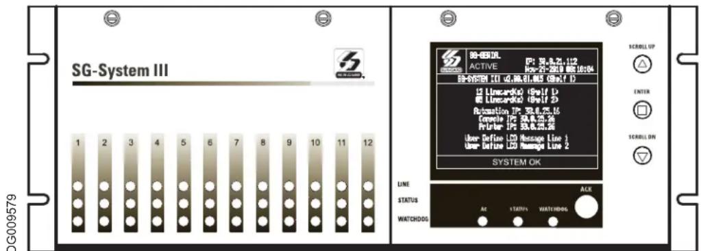
The SG-System III is a multi-platform receiver intended for remote monitoring of commercial fire and burglary systems. The SG-System III equipped with SG-DRL3/SG-DRL3E/SG-DRL3-2L/SG-DRL3-IP can monitor up to 48 telephone lines, 24 IP communication line cards, or a combination of the two. The SG-System III time and date stamps all received alarm signals which are then transmitted to a central station computer via TCP/IP or RS-232 port; transmitted directly to a printer using the parallel printer port, RS-232 printer port and/or TCP/IP; and viewed on the LCD of the front panel while the receiver is in the manual state. System configuration and phone line profiles can be programmed using a PC with SG-Systems Console or locally using the scroll buttons and LCD. Each shelf can house up to 12 SG-DRL3, SG-DRL3E, SG-DRL3-2L or SG-DRL3-IP in any combination.
System Overview
SG-DRL3/SG-DRL3E/SG-DRL3-2L
- Patented Caller Identification (Call Display) capability
- Patent pending AHS (Automatic Handshake selection)
• Patented virtual configurations
• Non-volatile memory on line cards for programming and event buffer - Flash download for software upgrades for all supported line cards and the SG-CPM3
• DSP technology (patent pending) - Up to 64 different options set (profiles per line card)
- Up to 8 different handshakes per profile
• Large, easy to read LCD (Liquid Crystal Display) - All modules function individually to help ensure uninterrupted operation during hardware or software upgrades
- All cards are Hot Swappable. Cards can be removed and replaced without removing power from the system or compromising the system performance
• 24 line cards maximum per redundant receiver - 512-event memory buffer on each individual line card
• Real-time clock - One parallel printer port, one serial printer port, one serial automation port and one ethernet (10/100BaseT) connection per rack
- Events can be manually acknowledged by an operator.
- Programmable serial ports
- Continuous verification of the computer-receiver links with the 'heartbeat' function
- Fast transmission of multiple alarms to the computer and printer to ensure operator's quick response
- Telephone Line and Ethernet link supervision
- Rack mountable in standard 19 inch rack. For UL listed installations use IMRAK 1400 or other equivalent listed enclosure.
SG-DRL3-IP
SG-DRL3-IP line card features include the following:
- Provides higher line security than conventional dial up panels with the polling feature.
- Quicker transmission since dialing or handshaking is not required.
• Network trouble detection is displayed on the LCD, printer and automation software. - Static IP address for programming of the network protocols.
- Ability to receive IP alarm messages from compatible communicators in either SIA or Contact ID.
- The T-LINK accounts and data encryption keys will be stored in the local line cards IP table.
- Data network polling environment for replacement of an existing DVACS network. Meets the 90-second ULC requirement for this option.
NOTE: The SG-DRL3-IP can receive data from all DSC IP communicators. Please see the communicator manual for compatibility limitations.
Approvals
Industry Approvals
• UL 1610 Central Station Burglar Alarm Units
- UL 864 Standard for Control Units and Accessories for Fire Alarm Systems
• CAN/ULC-S304:2016- REV 1 Control Units, Accessories and Receiving Equipment for Intrusion Alarm Systems.
• CAN/ULC-S559-13 Equipment for Fire Signal Receiving Centres and Systems
- FM approved
• EN60950-1:2006 Standard for Information Technology Equipment.
• AS/NZS 60950.1:2003 Information Technology Equipment - Safety
- CISPR22 Information Technology Equipment - Radio Disturbance Characteristics - Limits and Methods of Measurements
- EN50130-4 Immunity requirements for components of fire, intruder and social alarm systems
This equipment shall be installed in accordance with the requirements of NFPA72, NFPA70, UL827 and the authority having jurisdiction.
SG-System III with SG-DRL3-IP Line Card is ULC listed for active communication channel security level A1 - A4 when used in conjunction with T-Link TL250 and T-Link TL300(CF), TL260(R), TL280LE(R), LE2080(R), TL280(R)E, TL880LT,
TL880LE, LE9080, 3G9080, HS3128/032/248, LE4010(CF), LE4020(CF), 3G4010(CF) Internet/Intranet and/or LTE/HSPA alarm communicators. For this type of application the supervision and encryption features have to be enabled.
For ULC Installations the equipment shall be installed in accordance with the requirements of ULC-S561 and ULC-S301 Standards and the authority having jurisdiction.
For UL864 Commercial Fire applications, the following compatible communicators can be used with receiver model SG-System III SW Ver. 2.0x (using line card model SG-DRL3-IP SW Ver. 2.3x):
LE4010/LE4010CF SW Ver. 5.x
LE4020/LE4020CF SW Ver. 4.x
3G4010CF SW Ver. 4.x
TL300/TL300CF SW Ver. 1.5
The transmitter supervision (Option [13] in SG-DRL3-IP line card) shall be set to 60 minutes for single path and to 6 hours for multiple path performance-based technologies.
UL864 Programming Requirements
Table 1: UL864 Programming Requirements
| NOTICE to Users, Installers, Authorities having Jurisdiction, and other involved parties | ||||
| This product incorporates field programmable software. In order for the product to comply with the requirements in the Standard for Control Units and Accessories for Fire Alarms Systems, UL 864, certain programming features or options must be limited to specific values or not used at all as indicated below. | ||||
| SG-CPM3 | ||||
| Q# PogmOptPemichLL864 | (Y/N) | Possible Settings Settings Permitted (UL 864) | ||
| 12 | Heartbeat Timer | Y | 00-FF | Not allowed 00 |
| 13 | Mutc Buzzer | N | ON/OFF | OFF |
| 16 | PSU 1 Mask | N | ON/OFF | OFF |
| 17 | PSU 2 Mask | N | ON/OFF | OFF |
| 18 | DCA 1 Mask | N | ON/OFF | OFF |
| 19 | DCB 1 Mask | N | ON/OFF | OFF |
| 1A | DCA 2 Mask | N | ON/OFF | OFF |
| 1B | DCB 2 Mask | N | ON/OFF | OFF |
| 1C | Reserved | N | ON/OFF | OFF |
| 1D | Reserved | N | ON/OFF | OFF |
| 1E | Fan 1 Mask | N | ON/OFF | OFF |
| 1F | Fan 2 Mask | N | ON/OFF | OFF |
| 20 | Mask UPS 1 AC | N | ON/OFF | OFF |
| 21 | Mask UPS 1 Bat | N | ON/OFF | OFF |
| 22 | Mask UPS 2 AC | N | ON/OFF | OFF |
| 23 | Mask UPS 2 Bat | N | ON/OFF | OFF |
| 24 | Mask SG TCP 1 | N | ON/OFF | OFF |
| 25 | Mask SG Serial 1 | N | ON/OFF | OFF |
| 26 | Mask SG TCP 2 | N | ON/OFF | OFF |
| 27 | Mask SG Serial 2 | N | ON/OFF | OFF |
| 28 | Mask TCP Printer 1 | N | ON/OFF | OFF |
| 29 | Mask Parallel 1 | N | ON/OFF | OFF |
| 2A | Mask SG Serial 1 | N | ON/OFF | OFF |
| 2B | Mask TCP Printer 2 | N | ON/OFF | OFF |
| 2C | Mask Parallel 2 | N | ON/OFF | OFF |
| 2D | Mask SG Serial 2 | N | ON/OFF | OFF |
| SG-DRL3/SG-DRL3-2L | ||||
| Q# PogmOptPemichLL864 | (Y/N) | Possible Settings Settings Permitted (UL 864) | ||
| 04 | 2-Way Audio Activation Time | Y | 00-FF | 00 |
| 1C | BUSY OUT (For SG-DRL3 only) | Y | 00-FF | 00 |
| 042 | BUSY OUT (For SG-DRL3-2L only) | Y | 00-FF | 00 |
| 2F | Online Time Out | Y | 00-FF (00-255s) | 00 |
| 7A | 4 and 5 Digit Account Codes to Activate | Y | 00-FF | 00 |
| 7B | 2-Way Audio | |||
| 7C | 3-Digit Account Codes to Activate 2-Way | Y | 00-FF | 00 |
| 7D | Audio | Y | 00-FF | 00 |
| Alarm Codes to Activate 2-Way Audio | Y | 00-FF | 00 | |
| Audio Zone Code | ||||
| Note: for Commercial Fire applications, a DACT shall automatically initiate and complete a test signal transmission sequence to its associated receiver (SG-DRL3/SG-DRL3-2L line cards) at least once every 6 hours. The Automation Software connected to the receiver at the supervising station will indicate the absence of the test transmission (change settings from 24 hours to 6 hours). | ||||
| SG-DRL3-IP | ||||
| Opt# Program Option Permitted in UL 864? | (Y/N) | Possible Settings $settings Permitted (UL 864) | ||
| 13 | Transmitter Failure Debounce Time | Y | 5-65535 | 3600 (1 h)/21600 (6 h) |
| 15 | Transmitter Restoral Debounce Time | Y | 5-65535 | 300 |
| 19 | Mask Transmitter Restoral | N | OFF | OFF |
| 1A | Mask Transmitter Failure | N | OFF | OFF |
| 1B | Mask Transmitter Swap | N | OFF | OFF |
| 1C | Mask Transmitter Unencrypted | N | OFF | OFF |
| 1D | Mask Invalid Report | N | OFF | OFF |
| 1E | Mask Unknown Account | N | OFF | OFF |
| 1F | Mask Supervised Acc Exceeded | N | OFF | OFF |
Parallel Printers
For UL and ULC Listed applications the following UL/ULC Listed printer can be used with the SG-System III:
- Seiko DPU-414
Serial Printers
For UL and ULC Listed applications the following UL/ULC Listed printer can be used with the SG-System III:
- Seiko DPU-414
NOTE: Do NOT use printer cables that have only 1 common ground wire.
UL Manual Mode
For UL manual mode, each event will activate the internal buzzer to be acknowledged manually. Each event will also be sent automatically to the connected printer.
For Central Station applications, the signaling performance of each DACT (Digital Alarm Communication Transmitter) shall be manually tracked. Failure to receive a signal from a DACT over 24 hour period shall be handled as a trouble signal.
Description (Hardware)
Basic Configuration: The basic configuration consists of one 19" rack mounted chassis comprising the following:
- SG-BP3 Backplane provides interconnection of modules and communications interface
- SG-CPM3 Module contains the CPU that controls all communication to and from up to 24 receiver modules, printers, including 2 serial ports, a parallel port and an ethernet connection.
- SG-PSU3 Power Supply Unit provides power to all modules of the system.
- SG-DC/DC3 provides 5VDC power output required for the SG-DRL3 line cards. A slot exists for a second SG-DC/DC3 voltage converter. In the event of a failure, the redundant SG-DC/DC3 can be removed/replaced without powering down the unit.
- SG-PSC3 (Power Supply Controller) monitors the states of the power and fan for each SG-MLRF3.
- SG-MLRF3: The metal rack of the SG-System III that incorporates the LCD and SG-BP3.
- SG-DRL3/DRL3E Line Card: Each SG-DRL3/DRL3E line card monitors one telephone line. Stores on the card up to 64 profiles for data management including 8 different handshaking protocols. Each card has a 512-event buffer.
- SG-DRL3-2L Line Card: Each SG-DRL3-2L line card monitors up to two telephone lines. Stores on the card up to 64 profiles for data management including 8 different handshaking protocols. Each card has a 512-event buffer.
- SG-DRL3-IP Line Card: Each SG-DRL3-IP line card supports up to 1536 IP transmitters and can supervise up to 512 transmitters. Each line card has a 512-event buffer.
SG-BP3 Backplane
The SG-BP3 interconnects system modules and racks as well as providing communication outputs as indicated in figure 1-6. Figure 1-2
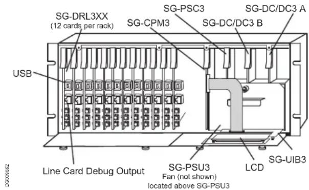
SG-PSU3 Power Supply Unit
The SG-PSU3 is the SG-System III power supply. The SG-System III requires a 120VAC/60Hz input power source. A power cord with a IEC connector is required. The model SG-System III CE requires a 240VAC, 50Hz input power source.
NOTE: For UL/ULC installations use only 120VAC/60Hz to power the SG-System III.
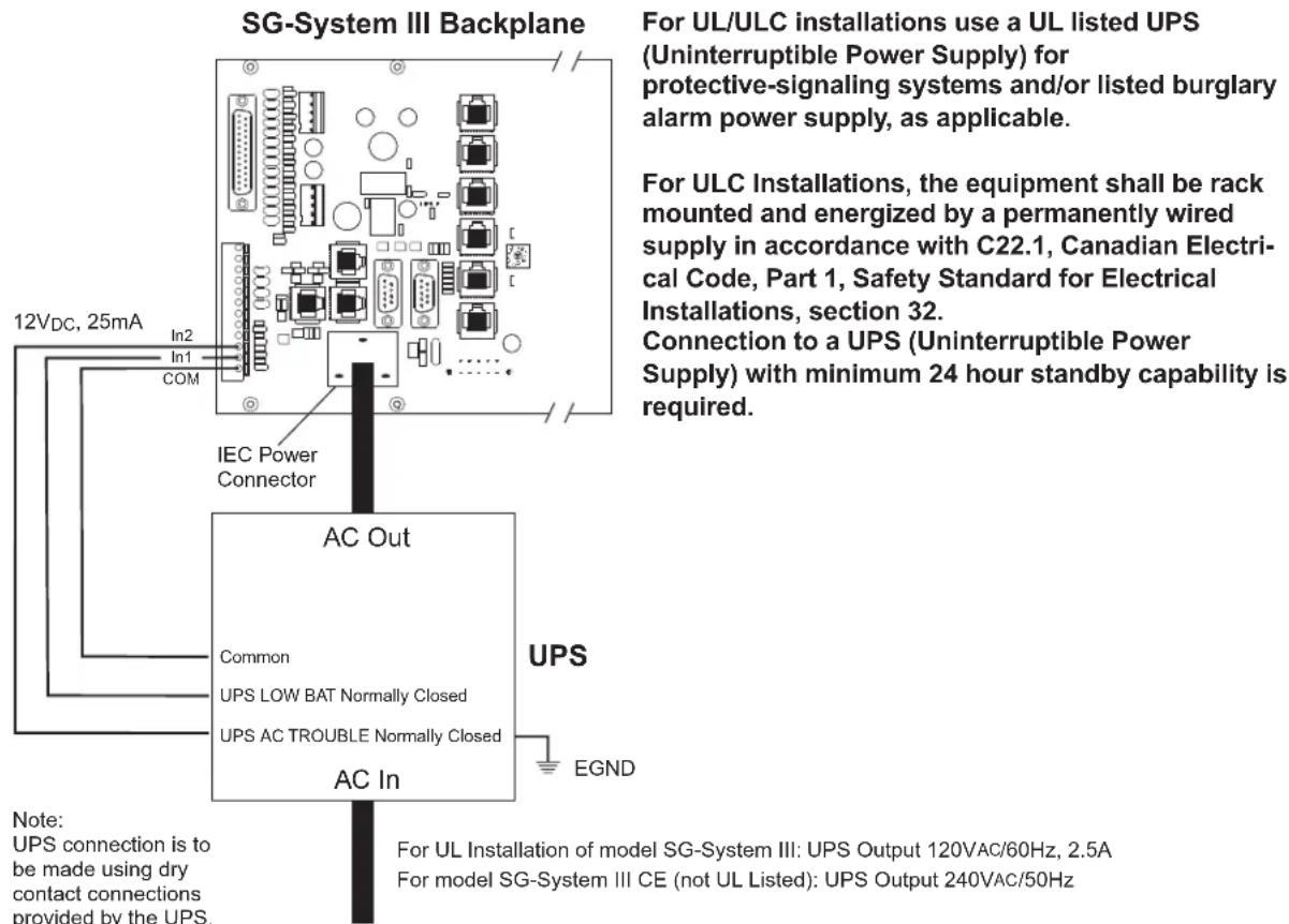
For UL installations use UL listed UPS Power Supply for protective signaling systems and/or listed burglar alarm power supply, as applicable.
The model SG-System III CE is not UL/ULC Listed.
Electrical Specifications:
SG-System III UL
- Input voltage range: 120VAC
• Frequency: 60Hz - Input current: 2.5A max (RMS) @120VAC
SG-System III CE
- Input voltage range: 240VAC
- Frequency: 60Hz
- Input current: 2.5A max (RMS) @ 240VAC
In a 2-rack configuration, a redundant SG-PSU3 can be inserted in the second shelf. In the event of a SG-PSU3 failure, the redundant SG-PSU3 automatically assumes operation. These modules are Hot Swappable (can be removed/replaced while the system is in operation) if a working redundant SG-PSU3 is installed.
SG-CPM3 Central Processing Module
The SG-CPM3 Central Processing Module collects system information and directs line card information to the appropriate outputs. Along with its built-in scroll buttons and large LCD message screen, the SG-CPM3 features TCP/IP, parallel printer and two serial RS-232 ports for computer interface capability. The printer is supervised for loss of power, off-line, paper out and other trouble conditions. The communication link to the automation computer through the RS-232 and TCP/IP port can be monitored by the supervisory heartbeat transmissions.
Line Cards
The SG-System III supports a maximum of 24 line cards. Each line card is equipped with non-volatile memory to record events. For each POTS card (SG-DRL3, SG-DRL3E and SG-DRL3-2L), calling source (Caller ID, ANI and calling name) capability is built-in and telephone numbers can be printed out, sent to automation and stored in memory. Events and informa-
1
tion stored in memory may be printed at any time. The SG-DRL3-2L and SG-DRL3E may perform flash updates over the front edge USB port connection.
The SG-DRL3/SG-DRL3E/SG-DRL3-2L receives ANI (Automatic Number Identification) and/or DNIS (Dialed Number Identification Service) via the Telco connection. This information allows the Sur-Gard System III to automatically change profiles for each received call. This eliminates dedicated line pool hardware. The DNIS information is used in a look-up table, which sets up virtual line pools to identify security formats and extend account numbers. Standard DNIS is supported up to 10 digits. Each dialed number would have formerly been a line pool on conventional line cards.
The SG-DRL3-IP (UDP) Receiver Module functions as a LAN or WAN server to many remote clients (the transmitters). The SG-DRL3-IP line card receives alarm events from the transmitter/panel decoding them before forwarding the signals to the SG-CPM3 for subsequent output to the printer and automation outputs.
After a SG-DRL3-IP has been installed and configured, it will listen on a programmed port and await communications from transmitters which have been configured to connect to that specific receiver. After communication has been established, the transmitter will enter its normal operating mode (waiting for panel polls, transmit heartbeat signals, alarm messages and DLS/SA download messages). The SG-DRL3-IP will log the connection and generate the appropriate event which will be forwarded to the SG-CPM3. The SG-DRL3IP also features flash downloads through Ethernet for fast software upgrades.
When an alarm message is generated by the transmitter, it will send the message in a UDP/IP frame and transmit it to the receiver (this communication can be optionally encrypted - reference transmitter documentation to determine if encryption is supported by the device). When an alarm message is received from the transmitter/panel, the receiver will strip off the UDP frame and decrypt the message. It will then send an appropriate response (ACK or NAK) back to the transmitter/panel. The timing will follow the standard timing requirements of the panel. If the message was a valid alarm event, the event will be sent to the appropriate connected printer and automation devices.
The SG-DRL3-IP line card receives heartbeats from all network supervision enabled transmitters periodically. This allows the receiver to determine whether the transmitters are still online. The receiver maintains a table of all installed transmitters and monitors their status (presence/absence, installed software versions, MAC addresses for swap detection purposes, and other network statistics).
The SG-DRL3-IP line card can be programmed with various configuration parameters and options, including receiver IP address, sub net mask, and default gateway address. Configuration parameters are password protected. The default password can be changed for maximum security.
The SG-DRL3-IP line card is programmed with a globally unique MAC address during production. This MAC address is NOT re-programmable.
NOTE: Each SG-DRL3-IP Receiver Module can monitor up to a maximum of 1536 accounts of which 512 accounts can be supervised.
SG-BP3X Interface Module
(One required per rack if SG-DRL3, SG-DRL3E, or DRL3-2L are used)
This 19" Rack-mounted panel interfaces with the SG-System III Telco connector to provide 24 RJ-11 connectors for direct connection to telephone lines.
NOTE:
SG-DRL3/SG-DRL3E: On the BP3X, the B ports are the channels used for 2-way audio or back-up telephone line.
SG-DRL3-2L: On the BP3X the B ports are the channels used for channel 2 of the line card.
Figure 1-3 Front

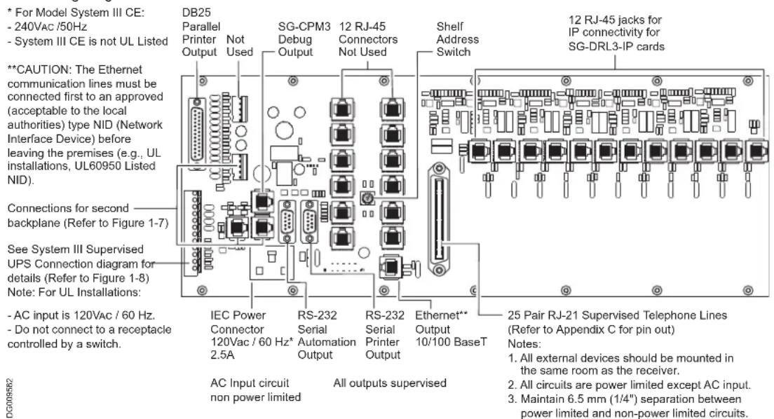
- Connections for Redundant SG-System III: Refer to Figure 1-7 SG-System III Redundancy Wiring Diagram.
- Line Card Debug Output: Connect the RJ-45 end of the debug cable to the debug output jack.
Connect the female DB-9 connector to the serial port of a computer (COM1 port - DB-9 male).
Figure 1-4 SG-CPM3 Debug Cable
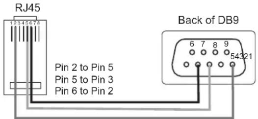
- SG-DRL3 Debug Output: Connect the RJ-45 end of the debug cable to the debug output jack on the front of the line card. Connect the female DB-9 connector to the serial port of a computer (COM1 port - DB-9 male).
Figure 1-5 SG-DRL3 Debug Cable

- IEC Power Connector: Provides local power line connection (cable is not supplied).
Figure 1-6, SG-System III Wiring Diagram
WARNING: To reduce the risk of electric shock the product is provided with a grounding type power supply IEC receptacle. Connect product using an appropriate IEC cable to a grounded receptacle.
- RS-232 Serial Automation Output: Provides serial connection to a local computer running automation software. A null modem serial cable must be used.
1
- RS-232 Serial Printer Output: Provides serial connection to a local computer or serial printer. A null modem serial cable must be used.
- 25 Pair Telco Connection: Connects directly to the local PBX or to SG-BP3X (Refer to Appendix B for pinouts).
- Ethernet Output 10/100 BaseT: Traditional automation communication is provided via port 1025 on the Ethernet connection. This primary port is a Sur-Gard standard output and provides Sur-Gard standard automation protocol output. All or a number of virtual receiver types can be mapped to the Sur-Gard output.
CAUTION: The Ethernet communication lines must be connected first to an approved (acceptable to the local authorities) type NID (Network Interface Device) before leaving the premises (e.g., UL installations, UL60950 Listed NID).
Figure 1-7, SG-System III Redundancy Wiring Diagram

| Switch Setting | Speed(Printer and Automation) | Shelf |
| 1 57,600 1 | ||
| 2 57,600 2 | ||
| 5 520,000 1 | ||
| 6 520,000 2 |
Figure 1-8, SG-System III UPS Supervision Connection Diagram
WARNING: To reduce the risk of electrical shock, the product is provided with a grounding type power supply IEC receptacle. Connect product using an appropriate IEC cable to a grounded receptacle.
Table 2: Loading Capacities for Hunt Groups
| Number of Lines in Hunt Group | |||||
| S y s t | e | m | L | o | |
| Number of initiating circuits NA 5,000 10,000 20,000 20,000 | |||||
| Number of DACTs | NA | 500 | 1,500 | 3,000 | 3,000 |
| With DACR lines processed serially (put on hold, then answered one at a time) | |||||
| Number of initiating circuits | NA | 3,000 | 5,000 | 6,000 | 6,000 |
| Number of DACTs | NA | 300 | 800 | 1,000 | 1,000 |
NA: Not allowed
Figure 1-9, SG-System III Power Limited Circuit Separation from Non-Power Limited Circuit Diagram

Receiver Setup and Operation
Sur-Gard recommends testing the receiver before actual installation. Becoming familiar with the connections and setup of the unit on the workbench will make final installation more straightforward.
The following items are required:
• IEC power supply cord
- One telephone line
• One or more dialer or digital control panel(s)
- Unpack the components for the SG-System III.
NOTE: Carefully unpack the receiver and inspect for shipping damage. If there is any apparent damage, notify the carrier immediately.
- Unscrew the front thumb screws and open the front plates.
NOTE: Before inserting the SG-CPM3, connect the ribbon cable from the SG-UIB3 board. Before inserting the SG-PSC3 connect the LCD power cable.
- Starting with slot 1, insert all cards in the rack to their appropriate positions. Ensure that there are no open slots between cards. (refer to figure 1-2).
- Insert the SG-PSU3 into the rack and screw in the thumb screw.
- Connect a telephone line to the corresponding line on the SG-BP3.
- Connect the main power using a standard computer IEC cable (not supplied).
- The LCD will power up and display internal troubles (e.g., printer, computer, telephone line fault). The SG-DRL3 that has the telephone line connected to it will have its red LED off. If the LED is on, make sure the telephone line is connected to the correct port.
- Press the ACK button until all of the initial signals have been acknowledged (ACK button has stopped flashing and the buzzer has been silenced).
NOTE: Internal diagnostics may require more than one minute during the power up sequence.
- Send a signal from a control panel to the receiver. The signal will be displayed on the LCD. Press the [ACK] button to silence the buzzer and clear the signal from the LCD.
Description (Operation)
Operation with Default Programming
Without any changes to the factory default programming, the receiver operates as indicated below:
- Answers incoming calls on the first ring
- Sends the following handshake order:
1 2300 Hz
2 1400 Hz
3 Dual-tone
4 SIA FSK
5 ITI, Modem IIE/IIIa2
6 Modem II
- Receives most communication formats, except for 3/2, 3/1 checksum, SKFSK, 4/2 extended, and 4/2 checksum (see Option 95).
- The above formats can be manually selected
- Signals can be displayed on the debug output computer as they are received. The signals are then sent to the printer and computer connected to serial port COM1 or to the 10/100BaseT. The default event codes described in the SG-DRL3 Library Decoding and Event Codes Table will be used with the Sur-Gard automation communication protocol to send signals to the computer, if connected.
- If a computer is not connected press the [ACK] button on the SG-CPM3 to silence the buzzer and to clear the alarm(s) from the LCD display.
1
Virtual Connectivity
Each SG-CPM3 has one static IP address and a number of associated ports. The configuration management, done from the Console Software, is located on port 1024. The SG-Systems Console software is provided for Microsoft Windows operating system (refer to the console documentation for compatibility listing), which provides a graphical style menu for configuration management. Additional features are available with the SG-Systems Console software including storage of virtual receiver setups and configuration wizards.
Status Addressing
Line card status is reported via physical addressing. Shelf and slot number are assigned automatically to each line card. All device status information is in Sur-Gard format. The reporting of status on this port, automation output and printer will relate to physical addressing.
Automation Input/Output (Port 1025)
Traditional automation communication is provided via port 1025 on the Ethernet connection. This primary port is a Sur-Gard standard output and provides Sur-Gard standard automation output.
Compatibility
Central station automation software packages such as:
• MAS • DICE • SIMS II • GENESYS
• S.I.S. • IBS • MicroKey • Bold
support the SG-System III Sur-Gard interface. Refer to automation software specifications for compatibility.
NOTE: Automation connections are considered supplementary per UL864 Listing. Compatibility with the automation software in a system used at a central station is intended to be handled under a separate UL1981 software and/or site certification evaluation.
Automation Protocols
The SG-System III receiver sends a variety of protocols to report signals to the central station computer via a TCP/IP and/or RS-232 port. A complete list of protocols is listed in Appendix E.
Data Byte Protocol
The SG-System III receiver uses a default configuration of 9600 Baud rate, 1-start bit, 8-data bits, 0-parity bits and 2-stop bits structure, to transmit and receive signals on the RS-232 port. This protocol can be programmed on the receiver to enable different configurations.
Acknowledgment of the Signal
The SG-System III receiver requires an acknowledgment signal [ACK] (Hex 06) from the computer software within 4 seconds for each message sent. Failure to receive the [ACK] will result in retransmission of the signal. After the fourth attempt, the SG-System III will indicate a communication failure on with the automation port. During a communication failure the SG-System III receiver will stop transmitting except for the heartbeat. In case of communication failure with the computer, the SG-System III receiver can store up to 512 events in its internal memory. Communication is resumed when the first heartbeat acknowledgment is received; all buffered information is then transmitted.
COM Responses
When the SG-CPM3 sends an event to the computer, it checks for 3 responses: ACK, NAK or Unknown/No Response. An ACK indicates that the computer automation received the event successfully. A NAK indicates the computer automation received the message but didn't understand it. The line card will attempt to send the messages 25 times. If after the 25th
1
attempt it receives a NAK from the computer automation, the SG-DRL3 will generate an internal communication error. After 20 NAKs the SG-CPM3 will send an internal communication error event to the printer and output the message to the printer in ASCII and attempt to move onto the next signal. Any other response from the computer automation, including no response will cause the SG-CPM3 to attempt to send the message again, up to 4 times. If after 4 attempts the SG-CPM3 does not receive a response or receives an unknown response, it will assume nothing is connected, generate an alarm and fall to the next active automaton port or manual mode.
Automation Absent
When the computer is not responding to transmissions, the SG-CPM3 will generate a 'SG-Serialx fail' or 'SG-TCP/IPx Fail' trouble. When the trouble occurs, the SG-CPM3 will continue to attempt to send a heartbeat signal to the computer until it gets a response. The SG-System III receiver will make 4 attempts, then wait for the next heartbeat period before making another 4 attempts. The typical heartbeat interval is 30 seconds.
| Supervisory Heartbeat Signal Protocol (1) | |
| 00000 R | 100000sssssssssss@sss[DC4]receiver number (First two digits are programmed section [14] of the CMP3. The remaining digits are always zeros). |
| s Space @ [DC4] | Character. |
| Supervisory Signal.Terminator, 14 Hex | |
This signal is used to supervise the communication between the receiver and computer automation. It is sent to the computer automation every 30 seconds and is programmable from the receiver. The computer automation should acknowledge this signal with an [ACK]. The SG-CPM3 can be programmed to send a heartbeat signal to the computer automation once every 01-99 seconds to test the connection between the SG-CPM3 and the computer automation (30 seconds is recommended). If a heartbeat fails to get a response from the computer automation, the SG-CPM3 will immediately transmit the heartbeat again, up to 4 attempts. The SG-System III, by default, will output the automation signals via TCP/IP. If TCP/IP fails it will switch to the Serial Automation output.
If the serial output fails, the SG-CPM3 will switch to manual mode, all signals will be displayed on the LCD and will require a manual acknowledgement. To re-establish connection with the TCP/IP a reset SG fall-back command must be generated from the Console software. If the line card buffers are full, the line cards will stop answering calls.
SG-System III SIA Internal Status Output
| 0RRLLL[#0000|NYYZZZZ] | |
| 0 Protocol ID | |
| RR Receiver number of the SG-CPM3 | |
| LLL Line card number, 000 signifies a SG-CPM3 Event. | |
| 0000 SG-System III account. | |
| NYYZZ SIA Event | |
| [DC4] Terminator, 14 Hex | |


SG-CPM3 Operating Modes
In This Chapter...
Contrast Adjust on page 18
Active Mode on page 18
Manual Mode on page 18
Standby Mode on page 19
System Trouble and System Information on page 19
AHS Table Management on page 19
2
Contrast Adjust
Press the Up and Enter buttons together to increase the contrast or press Down and Enter together to decrease the contrast. This operation can be done at any time after the power up sequence.
Active Mode
In Active mode, the primary connection to the computer is via TCP/IP networking on the 10/100 BaseT Ethernet connection for the automation computer. If this fails, then the output will go via serial RS-232. A command can then be sent through the SG-Systems Console software to revert back to TCP/IP when the connection is restored. The IP of the SG-CPM3 is displayed on the screen.
Figure 2-1, Active Mode
![SG-SERIAL(SG-SQLM) ACTIVE IP: 30.0.21.12 - 90.0.21.12 Nov-29-2010 08:18:04 Nov-29 SG-SYSTEM III v2.00.01.015 (Shelf) [SCL] = 16.00.01.015 12 Linecard(s) (Shelf 1) 12 Linecard(s) (Shelf 2) 05 Linecard(s) (Shelf 2) 05 Linecard(s) (Shelf 3) Automation IP: 30.0.25.16 (Full machines) Console IP: 30.0.25.26 (Newer IP: 30.0.25.26) Printer IP: 30.0.25.26 (Newer IP: 30.0.25.26) User Define LCD Message Line 1 User Default Line User Define LCD Message Line 2 User Default Line SYSTEM OK](/content/2026/06/1395096/images/16ceea0b59e28e4520d2bc019110918c6daf9ad00cd365d5ea05175298ded74f.jpg)
Manual Mode
For Manual mode, each event will activate the internal buzzer to be acknowledged manually. Each event will be sent automatically to the connected printer and displayed on the SG-CPM3 LCD. Messages longer than 80 characters will be displayed on two lines. Once the signal is acknowledged, it will be cleared from the screen.
Figure 2-2, Manual Mode
![IP: 30.0.21.112 Nov-17 2011 09:46:04 Alarm Buffer [0000, 0000] (Use to be BURGER) (No.2) 01/00-0000-NSC0000-Switching To Manual Mode [AOC-5800-5800] de: 02/02-0000-01-PER TEST REPORT [AOC-5800-5800-5800-5800-5800-5800-5800-5800-5800-5800-5800-5800-5800-5800-5800-5800-5800-5800-5800-5800-580 02/01-1234-NIV/8001 02/01-0000-02-PER TEST REPORT 02/02-0000-03-PER TEST REPORT 02/01-1112-38-BURGLARY SYSTEM OK](/content/2026/06/1395096/images/9e0d9e5ef224fb6fb8a470633eb955203b770dd0576cd6cc5e5ff00c90ff32c7.jpg)
NOTE: The SG-CPM3 will display a maximum of 5000 events which have not been acknowledged.
2
Standby Mode
When two SG-CPM3s are present, one SG-CPM3 will be in Active or Manual mode, and the other SG-CPM3 will be in Standby. If the active SG-CPM3 fails, the standby unit will automatically take over the control of the system. The IP of the SG-CPM3 is displayed on the screen.
Figure 2-3, Standby Mode

System Trouble and System Information
When a trouble is present on the SG-System III, the message "SYSTEM TROUBLE" will be displayed at the bottom of the screen.
- To view which trouble is present, press the UP and DN buttons simultaneously. All signals must be acknowledged before this is available.
- If no troubles are present, pressing the UP and DN buttons will enter open the System Information menu. In this menu items such as Version information, Product ID, IP address can be viewed. If troubles occur once the user is in the Trouble menu, pressing the UP and DN buttons again will allow the user to access the System Information menu.
• To return to the main screen, press the UP and DN buttons simultaneously, or wait for it to timeout before this is available.
AHS Table Management
New and modified AHS entries that are generated by incoming calls to line cards will be added to the backup CPM3. This operation will happen every 5 minutes. At this time, all entries that are new/modified will be synchronized with the other CPM3. If the two CPM3's are not able to communicate to each other then the synchronization of the new entries will fail.
When the SG-Systems Console sets the AHS table to the CPM3 it will be written to flash once the set is complete.
The SG-System III will log "AHS Database Full" once the AHS table has reached capacity. The SG-System III will continue to log "AHS Database Full" every day, at midnight, until space in the AHS table is made by deleting entries.
The AHS table size is 250,000 entries. This may be increased to 500,000 with the purchase of a license. Please contact your local sales representative for more information on how to acquire additional licenses.
NOTE: The SG-CPM3ROHS is required in order to have the additional AHS entries.

3
Line Card
In This Chapter...
Standby Mode on page 21
Line Fault on page 23
Standby Mode
SG-DRL3
After start-up, the line card enters Standby mode and monitors the telephone line and the SG-CPM3. Depending on the system's status, the following conditions will be displayed for each line card:
| LED ON OFF FLASHING | |||
| LINE(Red) | LineFault | LineNormal | N/A |
| STATUS(Yellow) | On-line Off-line *Error condition | ||
| WATCHDOG(Blue) | Line Card notfunctional | Line Card functional | |
*The number of flashes on the yellow LED indicates the following errors:
| Flashes Error | |
| 1 CPM absent | |
| 2 Line card clock not set | |
| 3 EBUS command to disable the line card was sent | |
| 4 Printer or computer buffer full. | |
| 5 Checksum failed when downloading flash ROM files. |
SG-DRL3E
After start-up, the line card enters standby mode and monitors the telephone line and the SG-CPM3. Depending on the system's status, the following conditions will be displayed for each line card:
| LED ON OFF FLASHING | |||
| Channel 1LINE (Red) Line Status (Yellow) | Fault NormalOn-line | Off-line | *Error condition |
| empty | |||
| WATCHDOG(Purple) | Line Cardnot functional | Line Cardfunctional | |
*The number of times the yellow LED flashes indicates the following errors:
| Flashes Error |
| 1 CPM Absent |
| 2 Line card clock not set |
| 3 EBUS command to disable the line card was sent |
| 4 Printer or computer buffer full |
| 5 Checksum failed when downloading flash ROM files. |
SG-DRL3-2L
After start-up, the line card enters Standby mode and monitors the telephone line and the SG-CPM3. Depending on the system's status, the following conditions will be displayed for each line card:
| LED ON OFF FLASHING | |||
| Channel 1Line (Red)Status (Yellow) | Line FaultOn-line | NormalOff-line *Error condition | |
| Channel 2Line (Red)Status (Yellow) | Line FaultOn-line | NormalOff-line | *Error condition |
| WATCHDOG(Purple) | Line Cardnot functional | Line Cardfunctional | |
NOTE: The SG-DRL3-2L has two channels. The Line LED will be used to indicate the status of channel 1. The Status LED will be used to indicate the status of channel 2 per table above.
*The number of flashes on the yellow LED indicates the following errors:
| Flashes Error | |
| 1 CPM absent | |
| 2 Line card clock not set | |
| 3 EBUS command to disable the line card was sent | |
| 4 Printer or computer buffer full. | |
| 5 Checksum failed when downloading flash ROM files. |
SG-DRL3-IP
After start-up, the line card enters Standby mode and monitors the network connection and the SG-CPM3. Depending on the system's status, the following conditions will be displayed for each line card:

| LED ON OFF FL | ASHING | ||
| LINE(Green) | NetworkPresent | NetworkAbsent | N/A |
| STATUS(Yellow) | TroubleCondition(s) | Off-line *Errorcondition | |
| WATCHDOG(Blue) | Line Cardnot functional | Line Cardfunctional | |
*The number of flashes on the yellow LED indicates the following errors:
| Flashes Error | |
| 1 | C P M a b s |
| 2 Linc card busy | |
| 3 Printer buffer full | |
| 4 Computer buffer full | |
| 5 Checksum failed when downloading flash ROM files. | |
c n t
Line Fault
The SG-DRL3/SG-DRL3E/SG-DRL3-2L verifies the telephone line voltage. The 'Line Fault' LED (Red) will come ON when the voltage drops below 12VDC.
When the line condition returns to normal, the 'Line Fault' LED will be shut OFF.
NOTE: Additional line fault operation if Backup Line option is enabled. See Backup Line option (Option 0E) for explanation.
SG-CPM3 Error
If the line card cannot detect the SG-CPM3 polling, the line card will start buffering incoming calls. Up to 512 alarm messages for the printer and computer will be retained in the line card event buffer. When the event buffer is full, the line card will stop answering calls and the status LED will begin flashing. When the SG-CPM3 Error condition is corrected, the alarm messages in the event buffer will be transmitted to the SG-CPM3 with the corresponding time/date the alarm has been received.
SG-DRL3/SG-DRL3E/SG-DRL3-2L Data Reception
During data reception, the yellow STATUS LED will turn on. The line card decodes all information received and stores the information in its Event Buffer. When a valid signal is received, the line card sends a kiss-off signal and transmits the decoded alarm signal to the computer and to the printer through the SG-CPM3. The line card will send each message it receives to the printer for review by the system operator.
Two messages may be sent to the printer to indicate reception problems: invalid report and communication fail.
Fault Data Message
When this problem is encountered, the following information is transmitted to the printer and the computer:
3
SG-DRL3/SG-DRL3E/SG-DRL3-2L
Printer:
Jun 25 1998-11:18:07-SS/OO-SG-12-234-0000-INVALID REPORT
Computer:
012234[#0000|NYNSSOO]
This output for account code '0000' indicates that data has been received, but is not valid (for example, there are unmatched rounds or incorrect parity).
Printer:
Jun 25 1998-11:18:07-SS/OO-SG-12-234-0000-COMMUNICATION FAIL
Computer:
012234[#0000|NYCSSOO]
This output indicates that a call was received, but no data was detected. The call may have been a wrong number, or the calling control panel was unable to connect with the receiver's handshakes. Computer message NACKed 25 consecutive times.
Printer:
Internal Comm. Error
Computer:
RRLLL[#0000|NRTSSOO]
NOTE: SS00 represents the shelf and slot of the line card that received the signal.
SG-DRL3-IP Fault Data Message
When this problem is encountered, the following information is transmitted to the printer and the computer:
Printer:
SG-12-234-AAAAAA-YN-*Invalid Report 192.158.8.34*
Computer:
012234[#AAAAAA|NYN*192.158.8.34*]
This output for account code 'AAAAAA' indicates that data has been received, but is not valid (e.g., The packet is encrypted and the SG-DRL3-IP does not have the proper key) or the T-LINK transmitter packet was rejected (NAK) four times by the receiver. Please also refer to Option 45.
Ethernet Interface
The SG-DRL3-IP has an Ethernet interface which operates as a 10BaseT/100BaseT IEEE 802.3 compliant Ethernet port. This port is accessible via a standard RJ45 connector. The IP address of the SG-DRL3-IP is programmable. The Ethernet port is used for system connections, including the transmitter and console ports.
The Ethernet communication lines must be connected first to an approved (acceptable to the local authorities) type NID (Network Interface Device) before leaving the premises (e.g., UL installations, UL60950 Listed NID).
Supervised Receiver Database
The receiver has the capability of monitoring IP transmitters that are set up as supervised units. The receiver will automatically keep track of new transmitters and indicate whenever a transmitter has been lost.


Programming/Operation
In This Chapter...
Introduction on page 28
Console Software on page 28
Debug on page 28
Manual Programming on page 29
SG-CPM3 Options on page 30
4
Introduction
The SG-System III can be programmed manually using the front panel; from a local computer or remotely using the TCP/IP network and SG-Systems Console software. The Debug output is intended as a testing and troubleshooting tool. Manual programming allows the user to program all of the SG-System III options for remote and local operation. Manual programming does not support the grouping of line cards into hunt groups or line pools.
Console Software
The Console software is intended to be the primary method of programming the system. Refer to the SG-Systems Console Manual for details.
Debug
The debug output is another method of accessing the line card's programmed options and diagnostics features. A debug cable is required to connect by serial communication from the line card to a standard PC running Windows 95 or higher software.
NOTES:
DRL3E/DRL3E-2L/DRL3-2L - Profiles 1-63 cannot be set through debug
DRL3 - If the line card reboots, changes made with set option through debug are lost. To make changes permanent, use the Write option.
ALL PROGRAMMING WITH THE DEBUG SETUP IS LOST WHEN THE SYSTEM IS POWERED DOWN OR WHEN LINE CARDS ARE REBOOTED OR REMOVED FROM THE RACK.
Debug Cable Connectivity
- Connect the RJ-45 end of the debug cable to the debug jack on the front of the line card.
- Connect the female DB-9 connector to the serial port of a computer. For debug cable pinouts, refer to figure 1-5.
Debug Setup
• Using Windows 95 or higher, point and click on the

- Select Propecuencies ▶ Communications ▶ HyperTerminal.
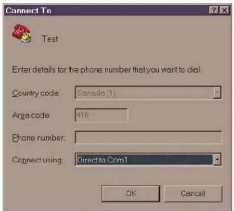
- A connection description window is displayed with a prompt on the 'Name' category. Type a name. Point and click on the 'OK' button.
- A phone number window is displayed. Choose the COM port required for connection and point and click on 'OK'.
NOTE: The SG-Systems Console may also be used allowing for PC's that do not have access to HyperTerminal to be able to program options and perform "logger functions". Refer to the SG-Systems console manual for setup instructions.
Figure 4-1
4
- The COMx properties windows are displayed. The configuration should be:
SG-DRL3 - bits per second 19200
SG-DRL3E/SG-DRL3-2L - bits per second 57600
SG-DRL3-IP - bits per second 19200
Data bits: 8
Parity: None
Stop bits: 1
Flow control: None
Figure 4-2

Set the DRL3E/DRL3-2L debug flags:
- Click on the 'OK' button after setting the configuration.
- The HyperTerminal window is displayed. Press any key. The debug menu is displayed.
- Press D to display the debug flags.
- Enter "06" for channel 1 or "07" for channel 2 and press enter. Channel 2 is on available on DRL3-2L line cards.
- Enter "03" and press enter.
If debug output is needed from 2 channels, repeat steps 3-5 for the other channel.
Manual Programming
The user interface consists of three buttons: the Scroll Up button, the Scroll Down button, and the Enter button. These buttons are used to access the programming of the SG-CPM3, and to view alarm and trouble messages in manual mode. They are located on the right side of the screen.
4
Figure 4-3

The Configuration mode allows programming of the various features and options available on the SG-System III. To enter the Configuration mode, press the [Enter] button.
Choose user 0 and enter the Master Access Code using the buttons; the default Master Access Code is "CAFE".
When the access code is entered, the screen will display the Configuration Menu.
CPM3 Options allow the user to customize the operation of the system TCP/IP addressing, Passwords, COM settings and other system functions. Refer to the description of all CPM3 options and their default settings.
System Functions
Reset the SG-CPM3
Restarts the SG-CPM3. This is required to make the changes to some options effective. For example, the IP address.
Date and Time
Sets the date and time of the SG-System III. This can also be done from the SG-Systems Console software.
System Information
Lists information such as CPM3 version, product ID, and MAC address.
Cold Boot Line Card
A cold boot will set the line card back to factory default settings.
Visual Indicator Test
When selected, the SG-CPM3 will activate all front user interface enunciators and buzzers for 5 seconds. All LEDs will activate and all pixels on the LCD will activate (display turns white) for this duration. Any outputs set for Buzzer Follow or Trouble Output activate during this test.
NOTE: Visual Indicator test should not be performed while other functions are active (such as line test/AHS Flash).
SG-CPM3 Options
NOTE: The following defaults are for the Primary SG-CPM3.
A Secondary SG-CPM3 will have the following MASK set to ON [1C, 1D, 20, 21, 22, 23, 25, and 27] at default, the remainder will be set to OFF. This is to reflect a full redundant system.
All references to OFF = option value of 00, and ON = option value of 01.
Option 01: IP Address
Default (10.0.7.100)
This section is the IP address of the SG-CPM3. The IP Address will be entered as a dotted decimal number. Example: 192.168.002.045.
Each segment of the IP address shall have a valid range from 000 to 255.
NOTE: For changes to this program option a reset of the unit is required before the new parameters are used.
Option 02: Subnet Mask
Default (255.255.0.0)
This section is the subnet mask of the SG-CPM3. The subnet mask will be entered as a dotted decimal number. Example: 255.255.000.000.
Each segment of the subnet mask shall have a valid range from 000 to 255.
4
NOTE: For changes to this program option a reset of the unit is required before the new parameters are used.
Option 03: Gateway Address
Default (0.0.0.0)
This section is the Gateway of the SG-CPM3. The gateway address will be entered as a dotted decimal number. Example: 192.168.002.001. Each segment of the Gateway IP address shall have a valid range from 000 to 254. The gateway is used in the event that the data being sent is not on the same network as the SG-CPM3. The data will need to be sent through a router. This is the IP address of the router.
NOTE: For changes to this program option a reset of the unit is required before the new parameters are used.
NOTE: The IP address and gateway must be on the same Subnet in order to change one or the other.
Option 04: Auto Update Time & Date
Default (0)
This option allows the automation to update the SG-CPM3 time via the TCP/IP port. When enabled, should the SG-CPM3 fail to get the time & date within 24 hours period (started after the last update is received or reset), it will generate a status message to the printer and automation, following the internal trouble protocol. The Trouble status on the SG-System III will not be affected. The Receiver Console time update function must be disabled when using this feature or there is a possibility that the SG-CPM3 will not remain synchronized with the automation PC.
Printer message: "Time&Date Update Fail"
Automation message: 0RRLLL[#0000|NRU0000]
NOTE: Confirm that the automation software package supports time and date update.
Option 05: Contrast Adjust
Default (80)
Allows the contrast of the message display screen to be adjusted. The contrast can also be adjusted from any screen by holding the UP and ENTER buttons simultaneously to increase the level, or by holding the ENTER and DOWN buttons simultaneously to decrease the level.
Option 06: Password Menu
Default (CAFE)
Allows the SG-System III users and passwords to be erased or changed. Sixteen users with 4-digit passwords are available for use on the SG-System III. User 0 is the Master user, and users 1 through F may be assigned to individual operators. The Master user will provide access to all menus, while the operators will have access to the SG-CPM3 settings as a view only (except passwords), other than to set the time and date.
This is to meet ULC-S559 Standard applicable to Fire Monitoring Equipment. All users are able to ACK alarm messages and view the Trouble menu.
To erase a user, program the password for that user to 'FFFF'.
NOTE: User "0" cannot be erased.
Option 07: COM1 Baud Rate
Default (9600)
Determines the baud rate at which the SG-CPM3 will communicate to the automation software via serial port 1. Valid selections are: 1200, 2400, 4800, 9600, 19200, 38400, 57600.
NOTE: For changes to this program option a reset of the unit is required before the new parameters are used.
4
Option 08: COM1 Data Bits
Default (8)
Determines the number of data bits used to communicate to the Automation Software connected on serial port 1. Choose 7 or 8 to indicate 7, or 8 data bits.
Option 09: COM1 Parity
Default (0)
Determines the parity of serial port 1.
| Numeric Setting Display Description | ||
| 0 None no parity (default) | ||
| 1 Odd odd parity | ||
| 2 Even even parity | ||
NOTE: The number of stop bits can not be changed and will always be 2.
NOTE: For changes to this program option a reset of the unit is required before the new parameters are used.
Option 0A: Serial Printer Format
Default (0)
The Serial printer is COM 2 on the receiver. Setting option [0A] to "01" (this will display as CTS pin high in programming mode), will require the CTS to be set high and print to both HyperTerminal™ and physical serial printer. By setting option [0A] to "02" (this will display as DCD pin high in programming mode), DCD will need to be set high. This option affects how the COM2 Serial Port is supervised. To disable the option set to [0].
To enable the printer messages to be outputted to a serial printer and a computer /HyperTerminal via the COM2, set to [1]. (This condition is for devices that set CTS pin HIGH.
To enable the printer messages to be outputted to a serial printer and a computer/Hyper Terminal via the COM2, set to [2].
(This condition is for devices that set the DCD pin HIGH.)
NOTE: For changes to this program option a reset of the unit is required before the new parameters are used.
Option 0B: Serial Baud Rate
Default (3) - 9600
Determines the baud rate at which the SG-CPM3 will communicate to the serial printer connected on serial port 2.
Valid entries are: 1200, 2400 4800 9600 19200 38400, 57600.
NOTE: For changes to this program option a reset of the unit is required before the new parameters are used.
Option 0C: Serial Data Bits
Default (8)
Determines the number of data bits used to communicate to the serial printer connected on serial port 2. Choose 7 or 8 to indicate 7 or 8 data bits.
NOTE: For changes to this program option a reset of the unit is required before the new parameters are used.
4
Option 0D: Serial Parity
Default (0)
Determines the parity of serial port 2.
| Numeric Setting Display Description | ||
| 0 None no parity (default) | ||
| 1 Odd odd parity | ||
| 2 Even even parity | ||
NOTE: The number of stop bits can not be changed and will always be 2.
NOTE: For changes to this program option a reset of the unit is required before the new parameters are used.
Option 0E: AHS Operation Options
Default (24) (disabled)
This option is used to program the time at which the AHS table will be saved to flash memory. Valid entries for this section are from 00 (12 AM) to 23 (11 PM) - and 24 (disabled).
Primary and Secondary SG-CPM3 must have this option programmed with the same value.
New and Modified AHS entries that are automatically generated by new incoming calls to line cards will be added to the backup CPM3 automatically via port 1030. This operation will happen every 5 minutes. At this time all entries that are new/modified will be synchronized with the other CPM3. If the two CPM3's are not able to communicate to each other then the synchronization of the new entries will fail.
A text message shall be outputted to the printer when AHS synchronization starts, stops, or fails.
A text message shall be outputted to the printer when AHS flash write starts, stops, or fails.
Option 0F: B32 Headers
Default (00)
Compatible with MAS B32 Automation Software through TCP/IP. To enable, change to [01].
B32 Headers apply only to TCP/IP automation messages, not serial messages or printer messages.
When enabled, ALL outgoing and incoming automation messages will contain 4 extra bytes at the start of each packet.
These four bytes are:
00 00 LL LL
Where:
LL LL = the BCD value of the size of the entire packet.
i.e., If the original length was 1B HEX bytes to be sent, the packet would be:
00 00 00 31
And the ACK back to the receiver would:
00 00 00 05 06
NOTE: The ACK back to the CPM3 (Ex."30 30-30 35 06" ASCII) will be at the end of the packet.
NOTE: For changes to this program option a reset of the unit is required before the new parameters are used.
4
Option 10: Input RRLLL Digits
Default (5)
Indicates the number of expected digits in the computer message header from the line card.
Option 11: Output RRLLL Digits
Default (5)
Indicates the number of digits the receiver will send in the header to the automation output. This should be left as 5 unless the automation software does not support the SG-System III output protocol. This will affect both System style message and Channel style messages.
Option 12: Heartbeat Timer
Default (30)
Determines at what time interval, in seconds, the heartbeat transmission will be sent to Serial Automation and TCP/IP port 1025. The heartbeat transmission is used to ensure that communications through Serial and TCP/IP are functioning normally when there is no traffic from the receiver. Any traffic from the receiver will reset the timer for the heartbeat. Therefore the heartbeat will only be sent if there is no signal sent during this programmed time. Enter a decimal number from 01 through 99 to determine the time interval between heartbeat transmissions. Enter the value 00 to disable heartbeat transmission.
NOTE: When 00 is used heartbeats will not be sent to automation software - this will result in the connection to the automation software being unmonitored.
NOTE: For UL Listed products, 00 is not permitted.
NOTE: For ULC-S304 applications, the heartbeat timer shall be set to 30 seconds.
Option 13: Mute Buzzer
Default (OFF)
A tone will sound when the system receives an alarm and is unable to forward the alarm message to automation (COM1 or TCP/IP). If enabled, the buzzer will not sound when an alarm is received and cannot be forwarded to an automation output.
For UL Listed products, the permitted setting is OFF.
Option 14: Receiver Number
Default (01)
The receiver number is used to identify the receiver when communicating to the TCP/IP Automation, COM1 and the printer. To change the receiver number, enter a new receiver number using the hexadecimal numbers "01" to "FE". This will be for all traffic unless overridden by other options.
Option 15: Printer Test
Default (01)
When this option is enabled, a test signal will be sent to all active printer(s) at 05:00 and 17:00 hrs. This option is set to "1" (on) by default. Printer message:
26 Nov 2003 16:41:25 - 26 Nov 2003-16:41:25-00/00-SG-01-000-0000--Printer Test Message
4
Option 16: Mask PSU 1
Default (00) - off
Some installations may not have the full configuration. This mask option is used to enable or disable the supervision of the Power Supply Unit for shelf 1. To disable reporting of the trouble, turn the appropriate option ON.
NOTE: PSU 1 is the SG-PSU3 installed in shelf 1
For UL Listed products, the permitted setting is 00.
Option 17: Mask PSU 2
Default (01) - on
Some installations may not have the full configuration. This mask option is used to enable or disable the supervision of the Power Supply Unit for shelf 2. To disable reporting of the trouble, turn the appropriate option ON.
NOTE: PSU 2 is the SG-PSU3 installed in shelf 2
For UL Listed products, the permitted setting is 00.
Option 18: Mask DCA 1
Default (00) - off
Some installations may not have the full configuration. This mask option is used to enable or disable the supervision of the right hand SG-DC/DC3 for shelf 1. To disable reporting of the trouble, turn the appropriate option ON.
NOTE: DCA 1 is the SG-DC/DC3 installed in shelf 1.
For UL Listed products, the permitted setting is 00.
Option 19: Mask DCB 1
Default (01) - on
Some installations may not have the full configuration. This mask option is used to enable or disable the supervision of the left SG-DC/DC3 for shelf 1. To disable reporting of the trouble, turn the appropriate option ON.
NOTE: DCB 1 is the SG-DC/DC3 installed in shelf 1.
For UL Listed products, the permitted setting is 00.
Option 1A: Mask DCA 2
Default (00) - off
Some installations may not have the full configuration. This mask option is used to enable or disable the supervision of the right SG-DC/DC3 for shelf 2. To disable reporting of the trouble, turn the appropriate option ON.
NOTE: DCA 2 is the SG-DC/DC3 installed in shelf 2.
For UL Listed products, the permitted setting is 00.
4
Option 1B: Mask DCB 2
Default (01) - on
Some installations may not have the full configuration. This mask option is used to enable or disable the supervision of the left SG-DC/DC3 for shelf 2. To disable reporting of the trouble, turn the appropriate option ON.
NOTE: DCB 2 is the SG-DC/DC3 installed in shelf 2.
For UL Listed products, the permitted setting is 00.
Option 1E: Mask Fan 1 Fail
Default (00) - off
Some installations may not have the full configuration. This mask option is used to enable or disable the supervision Fan trouble for shelf 1. To disable reporting of the trouble, turn the appropriate option ON.
For UL Listed products, the permitted setting is 00.
Option 1F: Mask Fan 2 Fail
Default (01) - on
Some installations may not have the full configuration. This mask option is used to enable or disable the supervision Fan trouble for shelf 2. To disable reporting of the trouble, turn the appropriate option ON.
For UL Listed products, the permitted setting is 00.
Option 20: Mask UPS AC 1
Default (01) - on
UPS AC trouble mask for shelf 1. If set, UPS AC trouble conditions are not reported.
OFF: Condition reported
ON: Condition not reported (masked)
Option 21: Mask UPS BAT 1
Default (01) - on
UPS Battery trouble mask for shelf 1. If set, UPS Battery trouble conditions are not reported.
OFF: Condition reported
ON: Condition not reported (masked)
For UL Listed products, the permitted setting is 00.
Option 22: Mask UPS AC 2
Default (01) - on
UPS AC trouble mask for shelf 2. If set, UPS AC trouble conditions are not reported.
OFF: Condition reported
ON: Condition not reported (masked)
For UL Listed products, the permitted setting is 00.
Option 23: Mask UPS BAT 2
Default (01) - on
UPS Battery trouble mask for shelf 2. If set, UPS Battery trouble conditions are not reported.
OFF: Condition reported
ON: Condition not reported (masked)
For UL Listed products, the permitted setting is 00.
Option 24: Mask SG TCP 1
Default (00) - off
SG TCP trouble mask for shelf 1. If set, SG TCP trouble conditions are not reported.
OFF: Condition reported
ON: Condition not reported (masked)
For UL Listed products, the permitted setting is 00.
Option 25: Mask SG Serial 1
Default (00) - off
SG Serial Automation trouble mask for shelf 1. If set, SG Serial automation trouble conditions are not reported.
OFF: Condition reported
ON: Condition not reported (masked)
For UL Listed products, the permitted setting is 00.
Option 26: Mask SG TCP 2
Default (00) - off
SG TCP trouble mask for shelf 2. If set, SG TCP trouble conditions are not reported.
OFF: Condition reported
ON: Condition not reported (masked)
For UL Listed products, the permitted setting is 00.
Option 27: Mask SG Serial 2
Default 01 - (on)
SG Serial Automation trouble mask for shelf 2. If set SG Serial automation trouble conditions are not reported.
OFF: Condition reported
ON: Condition not reported (masked)
For UL Listed products, the permitted setting is 00.
Option 28: Mask TCP Printer 1
Default 00 - (off)
SG TCP Printer trouble mask for shelf 1. If set, SG TCP Printer trouble conditions are not reported.
OFF: Condition reported
ON: Condition not reported (masked)
For UL Listed products, the permitted setting is 00.
Option 29: Mask Parallel Printer 1
Default 00 - (off)
SG Parallel Printer trouble mask for shelf 1. If set, SG Parallel Printer trouble conditions are not reported.
OFF Condition reported
ON Condition not reported (masked)
For UL Listed products, the permitted setting is 00.
Option 2A: Mask Serial Printer 1
Default 00 - (off)
SG Serial printer trouble mask for shelf 1. If set, SG Serial Printer trouble conditions are not reported.
OFF: Condition reported
ON: Condition not reported (masked)
For UL Listed products, the permitted setting is 00.
Option 2B: Mask TCP Printer 2
Default 01 - (on)
SG TCP Printer trouble mask for shelf 2. If set, SG TCP Printer trouble conditions are not reported.
OFF: Condition reported
ON: Condition not reported (masked)
For UL Listed products, the permitted setting is 00.
Option 2C: Mask Parallel Printer 2
Default (01) on
SG Parallel Printer trouble mask for shelf 2. If set, SG Parallel Printer trouble conditions are not reported.
OFF: Condition reported
ON: Condition not reported (masked)
For UL Listed products, the permitted setting is 00.
Option 2D: Mask Serial Printer 2
Default (01) on
SG Parallel Printer trouble mask for shelf 2. If set, SG Serial Printer trouble conditions are not reported.
OFF: Condition reported
ON: Condition not reported (masked)
For UL Listed products, the permitted setting is 00.
4
Option 2E: Number of Line Cards
Default (CC) - lines
This option is used to set the number of line cards polled by the SG-CPM3. The first digit of this option sets the number of line cards for shelf 2, and the second digit sets the number of line cards for shelf 1. Valid entries are from 1 to C (Shelf 1 CPM3) and 0 to C (Shelf 2 CPM3). The number of line cards being polled must be programmed the same for each CPM3.
Line cards must be installed in order occupying each slot sequentially starting from slot 1 of shelf 1 through to slot 12, for each shelf. This option does not require that shelf 1 be fully populated with line cards prior to populating cards on the second shelf.
Examples
12 line cards on shelf 1 and 3 line cards on shelf 2
-Both CPM3 would be programmed with 3C (shelf 1 - 12 line cards, Shelf 2 - 3 line cards)
6 line cards on shelf 1 and 9 line cards on shelf 2
-Both CPM3 would be programmed with 96 (shelf 1 - 6 line cards, Shelf 2 - 9 line cards)
Option 2F: Automation Mode
Default (01) Fallback
The TCP/IP connection is the primary output of the automation computer alarms. It is estimated that sockets may appear and disappear regularly as processes are terminated and reconstituted. After 5 seconds of socket loss, a socket loss is declared and automation output is shifted to the other connection levels.
This option is controlled by two digits. The first digit controls the 6th configuration option (split shelf reporting), the second digit controls the automation mode
| Value Description | |
| 00 Loop | |
| 01 Fallback | |
| 02 All | |
| 03 IP Fallback | |
| 04 Automatic IP | |
| 10 Loop – split shelf reporting enabled | |
| 11 Fallback – split shelf reporting enabled | |
| 12 All – split shelf reporting enabled | |
| 13 Setting is not valid – return to default setting | |
| 14 Automatic IP – split shelf reporting enabled | |
| 25-FF Setting is not valid – return to default setting | |
NOTE: For changes to this program option a reset of the unit is required before the new parameters are used.
First Configuration: Loop (0)
At start-up, the SG-CPM3 III will send to the TCP/IP until it fails, proceed to the RS232 until it fails, and proceed back to the TCP/IP until it fails, and so on. If neither TCP/IP nor RS232 are present, the CPM3 will switch to manual mode. See Automation Mode Diagrams for flow-charts of each mode.
4
Second Configuration: Fallback (1)
If both outputs are present, the SG-CPM3 will send to the TCP/IP until it fails, proceed to the RS232 until it fails, and if RS232 fails, switch to manual mode. While in manual mode, the SG-CPM3 will continuously try the RS232 connection and switch back to active mode if RS232 returns. The SG-CPM3 will not switch back to TCP/IP mode unless a reset SG fallback command is generated from the console. See Automation Mode Diagrams for flowcharts of each mode.
Third Configuration: All Mode (2)
The SG-CPM3 will always send to all connected outputs. If at least one output replies with an ACK, then the alarm is considered as transmitted whether the other output acknowledged it or not. This setting is NOT recommended. See Automation Mode Diagrams for flowcharts of each mode.
Fourth Configuration: IP Fallback Mode (3)
The system will send to the TCP/IP connection until it fails, reboot, and then send to the TCP/IP connection on the secondary shelf. If that fails, it will reboot, and then send to the serial output on the primary shelf. If that fails the CPM will reboot and send to the serial output on the secondary shelf. It will continue to send to the serial connection without stop, or until the reset fallback command is generated from the console, in which case it will re-try the TCP/IP connection.
Fifth Configuration: Automatic IP SG-Fallback (4)
This mode is similar to Fall Back except that when the TCP/IP connection is restored the SG-CPM3 will automatically return to the TCP/IP Interface to send events. This eliminates the need for the Reset SG Fall back from the SG-Systems Console.
Split Shelf Reporting
Split shelf reporting allows the receiver to have both shelves of the receiver output printer/automation messages independently. All signals for each shelf will be outputted by the corresponding CPM. In the event that one of the CPM modules is removed or fails, the other will automatically take over processing of all automation and printer messages.
Automation Mode Diagrams
Flow Diagram for Automation Loop Mode (0) and Automatic IP Fallback Mode (4)

flowchart
graph TD
    A["Power Up / Restart"] --> B["TCP Port Active?"]
    C["Automatic Fallback Mode (4)"] --> B
    D["Manual Re-start from Console (Reset Fallback)"] --> B
    E["Poll Automation"] --> B
    B -->|YES| F["Serial 1 Port Active?"]
    B -->|NO| G["Manual Mode"]
    F -->|YES| D
    F -->|NO| H["Manual Re-start from Console (Reset Fallback)"]
    G --> I["Manual Mode"]
    H --> J["Manual Re-start from Console (Reset Fallback)"]
Flow Diagram for Automation Fallback Mode (1)

flowchart
graph TD
    A["Power Up / Restart"] --> B{TCP Port Active?}
    B -->|YES| C["Poll Automation"]
    B -->|NO| D{Serial 1 Port Active?}
    D -->|YES| E["Manual Re-start from Console (Reset Fallback)"]
    D -->|NO| F["Manual Re-start from Console (Reset Fallback)"]
    E --> G["Manual Re-start from Console (Reset Fallback)"]
    F --> H["Manual Re-start from Console (Reset Fallback)"]
    G --> I["Power Up / Restart"]
    H --> J["Power Up / Restart"]
Flow Diagram for Automation All Mode (2)

flowchart
graph TD
    A["Power Up / Restart"] --> B{Serial 1 Port Active?}
    A --> C{TCP Port Active?}
    B --> D["YES YES"]
    C --> D
    D --> E["Poll Automation"]
    E --> F["NO"]
    F --> A
    C --> G["NO"]
4
Flow Diagram for Automation Automatic IP Fallback Mode (3)

flowchart
graph TD
    A["Power Up / Restart"] --> B{CPM (A) TCP Port Active?}
    B -->|NO| C["CPM(A) Reboot"]
    B -->|YES| D["Poll Automation"]
    C --> E{CPM (B) TCP Port Active?}
    E -->|NO| F["CPM(B) Reboot"]
    E -->|YES| D
    F --> G{Serial 1 (A) Port Active?}
    G -->|NO| H["CPM(A) Reboot"]
    G -->|YES| D
    H --> I{Serial 1 (B) Port Active?}
    I -->|NO| D
    I -->|YES| D
    J["Manual Re-start from Console (Reset Fallback)"] --> B
    K["Manual Re-start from Console (Reset Fallback)"] --> E
    L["Manual Re-start from Console (Reset Fallback)"] --> F
    M["Manual Re-start from Console (Reset Fallback)"] --> G
Option 30: Printer Mode
Default (00) - Loop
The printer outputs can be configured in a similar approach as the automation outputs except that only acceptable values are LOOP (01) or ALL (02). ALL is transmitting the printer message to all active ports. The first acknowledgement received will be used to process the next printer message.
NOTE: Order of sequence is TCP, Parallel and finally Serial. Sur-Gard does NOT recommend changing the default setting unless using more than one printer.
NOTE: The display for programming of the Printer Mode shall display the text label for the mode rather than the numeric value (example instead of 00 - it displays LOOP, instead of 02 - it displays ALL).
NOTE: For changes to this program option a reset of the unit is required before the new parameters are used.
4
Option 31: ACK Wait
Default (40)
Determines the acknowledge wait time, in tenths of a second, to be used for automation outputs before the CPM3 will try again (if no response is received within this interval). This timer starts after the signal is sent to the automation.
Enter a decimal number from 40 to 99 for 4.0 seconds to 9.9 seconds.
NOTE: For changes to this program option a reset of the unit is required before the new parameters are used.
Option 32: Date Format
Default (0)
Selects the format used to represent date for printer output.
Format [1] represents US format (display will read MM/DD/YY).
Format [0] represents International format (display will read DD/MM/YY).
Option 33: Protocol ID
Default (0)
When this option is programmed as "0" the CPM3 will output its internal messages in the following format:
0RRLLL[#AAAA|Nxxyy]
When this option is programmed as "S" the SG-System III will output its internal messages in the following format:
SRRLLL[#AAAA|Nxxyy]
S,0 (zero): protocol number
RR: Receiver number
LLL: Line number
AAAA: Account code, always 0000
Nxxyy: SIA event
Option 34: Time Correct
Default (000)
The SG-System III will synchronize its time with the SG-System III console application PC. However in some situations it may be desirable to automatically correct the time of the SG-System III. The SG-System III will update its time once an hour. Valid values are -590 to +590; value represents time in tenths of a second (i.e., 243 means 24.3 seconds).
NOTE: Positive values adjust the time forward and negative values adjust the time backward.
Option 37 and Option 38: License Key
Option 37: License key #1 Default (0000 0000 0000 0000 0000 0000 0000 0000)
Option 38: License key #2 Default (0000 0000 0000 0000 0000 0000 0000 0000)
The default size of the AHS table is 250000 entries. With the purchase of a license the table size can be increased to 500000 entries. When purchasing the license key for the CPM3 the Product ID will be needed. The product ID can be found in the System Information menu or retrieved via the SG-Systems Console in the Status Menu for the CPM3. Both CPM3's will need to have a valid license entered in order to have 500000 AHS entries on each. There are two sections for the license key (Option [37]: License key #1, and Option [38]: License key #2) and both of them must be programmed correctly. If the user has entered a license key in the product that is incorrect the receiver will output a printer only message "Invalid License Key" so that the user knows that the key entered is incorrect. If the key is 0's or correct no message will be generated. A key of all zeros is disabled.
NOTE: A cold boot will erase the license key.
4
Options 3E: RBUS Speed
The system communication bus (RBUS) baud rate is programmable for two different settings 57600 and 520000. Each shelf of the CPM3 can have its own baud rate programming. This is done to accommodate line cards that have different setting capabilities. Each CPM3 has two RBUS connections, one for Shelf 1 and one for Shelf 2. This will allow one CPM3 to be able to poll/retrieve messages from any line card on the system regardless of the baud rate. When configuring the System all line cards on a shelf must have the same baud rate setting. Any cards that do not have the correct setting will not be seen by the CPM3 and signals received by that line card will not be outputted.
| Value Shelf-1Bus Speed Shelf-2Bus Speed | |
| 00 57600 57600 | |
| 01 520000 57600 | |
| 02 57600 520000 | |
| 03 520000 520000 | |
| 04 - FF 57600 57600 | |
Line Card compatible baud rates
| Line Card Type Supported Baud Rates | |
| SG-DRL3 57600 | |
| SG-DRL3-IP 57600 | |
| SG-DRL3E 57600 or 520000 | |
| SG-DRL3-2L 57600 or 520000 | |
NOTE: Line cards capable of higher bus speeds will determine their bus speed based on the shelf selector switch. This method does not apply to the CPM3.
| Shelf selection | Linecard RBUS Speed | Shelf to be reported (printer and automation) |
| 1 57600 Shelf 1 | ||
| 2 57600 | Shelf 2 | |
| 3 Not valid – 57600 | Shelf 1 | |
| 4 Not valid – 57600 | Shelf 1 | |
| 5 520000 | Shelf 1 | |
| 6 520000 | Shelf 2 | |
| 7-16 | Not valid– 57600 | Shelf 1 |

5
Advanced Programming
In this Chapter...
SG-DRL3-2L/DRL3E System Options on page 48
SG-DRL3/SG-DRL3-2L Static Options on page 50
SG-DRL3/SG-DR13-2L Dynamic Options on page 61
5
Profiles Introduction
The DRL3/DRL3E/DRL3-2L 'virtual receiver' will load unique 'profiles' in order to effectively communicate with control panels. A profile is a set of pre-programmed line card options unique for a particular DNIS number. The 'DNIS' will point to a particular profile, which will then be loaded into the line card before the first handshake is sent. It is essential that the correct option be programmed for a profile in order to correctly communicate with the control panel. Each 'virtual receiver' can have a maximum of 64 profiles. To change the options for a particular profile, the SG-Systems Console software is provided. This software will allow the user/operator to edit the profiles.
NOTE: DNIS (Dialled Number Identification Service): This number represents the dialled number, or the number being called. ANI (Automatic Number Identification): This number represents the source of a call and allows the system to determine the handshake protocol. Caller ID: This number identifies the source of a call. For the purpose of this document, Caller ID and ANI will be referred to as Caller ID, but both can not be used at the same time. Contact your provider to determine which service is available. DNIS cannot be used with Caller ID, only ANI.
DNIS or Caller ID can be used for profile selection.
Line Cards Identification Number Handling:
Figure 5-1, Call Processing Flowchart

flowchart
graph TD
    A["Receive DNIS or Caller ID"] --> B{Correct amount of DNIS digits?}
    B -->|NO| C["Hang up and generate Communication fail"]
    B -->|YES| D["Send string to Lookup Table"]
    D --> E{Corresponding Profile?}
    E -->|NO| F["Use Profile 0"]
    E -->|YES| G["Point to Profile #"]
    G --> H["Use options from profile"]
    F --> H
    H --> I["Done"]
5
Each profile is made up of Static Options and Dynamic Options. The static options are the same for all profiles, but the dynamic options can be programmed specifically per hunt groups, panel type, etc. By receiving the DNIS or Caller ID, the appropriate profile can be selected through a look-up table "stored" on the line card.

Profile 0 is the default. When no Caller ID or unknown DNIS is received, or when the received number does not point to a profile, the default will be used.
Profiles are used to reduce on-line time, and for specific customers or panel/format types, one can have a profile with certain handshakes sent first. Also, some formats require certain options, and this can be pre-defined as well. Profiles allow for a more customized system. Rather than having a line card (or a receiver itself) devoted to certain customers, the SG-System III can handle any format at any time through the use of profiles. Each line card holds its own look-up table that can be shared through line pools, or shared within the entire receiver. Two types of tables are available, but only one type can be chosen. The first type, which consists of 100,000 entries, is used strictly with DNIS of up to 5-digits.
Table type 1:
DNIS Received Profile# to be used
| 00001 | 01 |
| 00002 | 03 |
| 00003 | 24 |
| ... | ... |
| 99999 | 45 |
The second type is used if ANI-Caller ID and/or DNIS are received, and can consist of up to 10,000 entries, with Caller ID or DNIS of up to 10 digits.
Table type 2:
| Caller ID Number | Convert Data Profile | |
| 05 603000 | Not Used | 0 |
| 05 603001 | Not Used | 1 |
| 05 603002 | Not Used | 2 |
| 05 603003 | Not Used | 3 |
| DNIS Number Convert Data Profile | ||
| 12345 | 54321 | 0 |
| 12346 | 54322 | 1 |
| 1234 | 54333 | 2 |
5
Each portion may contain 0-100,00 entries with the total of all the entries not exceeding 10,000. The receiver will first check through the Caller ID section if a Caller ID number is received. If only a DNIS number is received, or Caller ID is received but the Caller ID was not found, it will check in the DNIS section. On a standard receiver, the Automation output would look similar to the following:
1RRLLLssssssAAAAAsYsZZ[DC4]
1DDDDDssssssAAAAAsYsZZ[DC4]
On the line card, it will replace the RRLLL, which is normally the receiver number and the line card number, by the DNIS received or the convert data found in the table. This makes possible the duplication of accounts, as long as they are dialling different numbers.
The output will become:
Where DDDDD is the DNIS number. See Option 20/120 for more information on how to enable the combined table.
SG-DRL3-2L/DRL3E System Options
Option 006: Password Menu
Default (CAFE)
This password is only required if connecting directly to the line card for Code Uploads or performing other console operations directly to the line card (VIA USB). The Password menu allows for a single password to be programmed. The password is 4 hex digits in length. All entries are valid 0000-FFFF hex.
NOTE: This user cannot be erased.
Option 040: Channel Enable
Default (02)
This option is used to set the number of channels to be present on the line card. Valid entries are from 01 to 02.
01 - Only Channel one POTS is used - all reporting of status/trouble conditions for the second line will be masked and the channel will be busied out. Programming menu display will be C1.
02 - Both POTS channels are used. Programming menu display will be C1+C2. All other values are not valid. For channels that are disabled no information shall be displayed and no status troubles will be generated – any trouble conditions that exist when the channels are disabled will be restored after the unit has been reset.
NOTE: This option is hidden for the DRL3E.
Option 041: Line card number length
Default (0A)
This option is used to determine how many digits from the line card number will be sent to the output. You also have the option of displaying the number in hex or decimal. This option will also determine the Program Option 02/102/202 with one of the following:
01 Send only one hex digit to the printer or computer output (if you have a 2-digit line card number only the last digit will be sent to the output). If using DNIS to replace RRLLL then the output will be 3 digits: RRL.
02 Send 2 hex digit line card number to the output. If using DNIS to replace RRLLL then the output will be 4 digits: RRLL.
03 Send 3 hex digit line card number to the output (leading Zeros will be inserted prior to the line card number) If using DNIS to replace RRLLL then the output will be 5 digits: RRLLL.
0A Send 3-digit line card number in decimal and the 2-digit receiver number in decimal. If using DNIS to replace RRLLL then the output will be 5 digits: RRLLL (this option will only affect message output for POTS Channels and IP Channel).
0D Send 3-digit line card number in decimal and the 2-digit receiver number in Hex. If using DNIS to replace RRLLL then the output will be 5 digits: RRLLL.
NOTE: When setting this option, the line card Number Length option should always correspond to the number of DNIS digits being received. For example, if 5 digits are being received then the line card Number Length Option should be programmed to 3. This would cause the 5 digits of DNIS DDDDD to overwrite the standard RRLLL.
5
Option 042: Line card Busy out
Default (00)
This option allows the line card to seize the phone line in case of checksum error after download or when its internal buffer is full after loss of communication with the CPM3. Program with one of the following:
00 The line is seized if any of the conditions mentioned above occur.
01 The line is NOT seized if any of the conditions mentioned above occur. Once the event buffers of the receiver are full, the oldest event in the buffer will be removed to make room for the new event(s).
04 The line will be seized if the automation computer is absent. System will busy out ONLY if the internal computer buffer is full. If there is a loss of printer(s), any new alarms will not be buffered in the internal printer buffer.
05 The line will be seized immediately if there is a loss of automation software or no communication to the CPM.
NOTE: The status condition will be indicated on the LED even though the unit does not busy out the line. Example – set option to 01 (do not busy out) and have a loss of time present. The status will still be displayed on the status LED, but the system will not busy out.
If the option is programmed to 01, the line card will NOT buffer any new alarms once the internal buffer is full. Setting this option to 01 is NOT RECOMMENDED.
If this 01 is selected, the line card will overwrite the oldest alarm with a new alarm when the internal buffer is full.
Option 043: Line card Protocol ID
Default: (01)
RS-232 Format
S,0 (zero): protocol number
RR: Receiver number
LLL: Line number
AAAA: Account code, always 0000
Nxxyy = SIA event
[00] - Output for all internal signals is SRRL protocol
SRRLLL[#AAAA|Nxxyy]
[01] - Output for all internal signals is 0RRL (Zero) protocol
0RRLLL[#AAAA|Nxxyy]
Option 044: Line card Class Field
Default (04)
00 Send "0"s in C.L.A.S.S. field of CONCOMM/RBUS packet.
01 Send Receiver Line Card Number (RRLLL) from options in C.L.A.S.S. field.
02 Send DNIS in C.L.A.S.S. field.
03 Send Caller ID in C.L.A.S.S. field.
04 Send whatever option12 Caller Source is set to in the C.L.A.S.S. field.
05 Send the convert data from the DNIS/Caller-ID (combined) Conversion table in the C.L.A.S.S. field.
Example: DNIS is: 99802
Automation:
S99802[#1234|NBA0F10]
Printer:
03 Jun 2008 08:33:33 - 03 Jun 2004-08:33:32-01/01-SG-99-802-1234--Alarm Zone
5
SG-DRL3/SG-DRL3-2L Static Options: 00 - 2F
SG-DRL3 Option 01: Line Card Number
SG-DRL3-2L Option 101/201: Line Card Number
Default (01)
The line card Number provides a virtual identification code for each line card. Hexadecimal numbers '01' to 'FE' can be programmed in Option 01/101/201 to identify line cards.
SG-DRL3 Option 02: Line Card Number Length
Default 0A
This option is used to determine how many digits from the line card number will be sent to the output. You also have the option of displaying the number in hex or decimal.
Program Option 02/102/202 with one of the following:
01 Send only one hex digit to the printer or computer output (if you have a 2-digit line card number only the last digit will be sent to the output).
02Send 2 hex digit line card number to the output.
03Send 3 hex digit line card number to the output (leading Zeros will be inserted prior to the line card number).
0ASend 3-digit line card number as entered (no conversion).
0DSend 3-digit line card number in decimal (conversion from decimal to hex decimal. Receiver number will be outputted as programmed without any conversions.
NOTE: When setting this option, the line card Number Length option should always correspond to the number of DNIS digits being received. For example, if 5-digits are being received then the line card Number Length Option should be programmed to 3. This would cause the 5 digits of DNIS DDDDD to overwrite the standard RRLLL.
SG-DRL3 Option 03: Internal messages RS-232
Default (01)
When this option is programmed as "00", the channel will output its internal messages in the following format:
SRRLLL[#AAAA|Nxxyy]
If it is programmed as "01" internal messages will be output as
0RRLLL[#AAAA|Nxxyy]
Where:
S, 0 (zero) = Protocol number
RR = Receiver number
LLL = Line number
AAAA = Account code, always 0000
Nxxyy = SIA event
5
SG-DRL3 Option 04: 2-Way Audio Activation Time
Default (00)
This option determines how long, in 10-second increments, the 2-way audio function will be active once it is initiated. At the end of this time, the line card will hang up the line. Program a value from "01" to "FF" for 10 seconds to 2550 seconds. Three (3) minutes is the recommended length of time for the 2-way audio activation time. To disable the 2-way audio feature, program Option 04/104/204 as "00".
NOTE: Enabling 2-way audio will affect NFPA 72 system loading requirements. Refer to Par. 4-5.3.2.2.2 of NFPA 72 for details.
If the alarm panel sends a listen-in code activation request and audio is enabled for this format (Option 7F/17F/27F or B0/10B/20B), the receiver will remain in 2-way voice for a period of 60 seconds even if the activation time is not programmed.
For UL Listed products, the permitted setting is 00.
SG-DRL3 Option 05: Pre-H.S. Duration
SG-DRL3-2L Option 105/205: Pre-H.S. Duration
SG-DRL3 Default (0A), SG-DRL3E/SG-DRL3-2L Default (1A)
When the line card seizes the line, it will wait the time programmed at Option 05/105/205; then send the first handshake. The value programmed (hex) at this location will be multiplied by 100ms (e.g., 100ms, 200ms). The SG-DRL3 default is 0A, for 1000ms (100ms x default value).
The minimum time is 1 second. If the option is programmed with any value lower than 0A, the line card will use a 1 second delay. The maximum time for this option is 5 seconds (option programmed for 0x32) Option value higher than 0x32 will use a 5 second delay.
SG-DRL3 Option 09: First Ring Length
SG-DRL3-2L Option 109/209: First Ring Length
Default (05)
In order for the line card to detect an incoming ring, the ring signal must be ON for a minimum amount of time. This option allows the user to change the minimum amount of time the ring signal must be ON before the receiver will detect a valid ring length. The minimum ring duration allowed is 200 ms which corresponds to a value of 02 (200 ms). Values programmed will be multiplied by 100 ms. Values of 00 and 01 give a first ring length of 500ms.
SG-DRL3 Option 0A: Format ID Output
SG-DRL3-2L Option 10A/20A: Format ID Output
Default (00)
This option will allow the line card to output the format ID and profile that was used to receive the call. This output is to the printer only. The format for the output:
27 Nov 2009-18:51:25-01/06-SG-(PP|FF)-RR-LLL-EVENT MESAGE
Where PP is the profile number and FF is the format ID.
5
Format ID List
| Format Description Format | ID | Format Description Format | ID | Format Description Format | ID |
| 3/8 ACRON 1 Modem II Generic 5a 3/1 Pulse (*) 4D | |||||
| 4/8 ACRON 2 Modem IIE or IIIa2 5b 3/2 Pulse 4E | |||||
| 4/1 Express (*) | 10 | 4/3 Scscoa Super Speed | 69 | 4/1 Pulse (*) | 4F |
| 4/2 Express 11 Scscoa Open/Close | Super Speed | 6A 3/1 | Extended Pulse | 50 | |
| 3/8/1 Ademco Super Fast | 13 | SIA FSK Level 1, 2 and 3 | 6B | 3/1 Partial Extended Pulse | 51 |
| 4/8/1 Ademco Super Fast | 14 | Silent Knight FSK0 | 7A | 4/2 Sur-Gard | 7F |
| 4/8/1 with Checksum Ademco Super Fast | 15 | Silent Knight FSK1 | 7B | 4/2 with Checksum Sur-Gard | 7F |
| Contact ID (4-Digit Account) | 16 Silent Knight FSK2 o/p Type 1 | 7C | 4/3 Sur-Gard 80 | ||
| Bellcore Caller-ID | 1B | Silent Knight FSK2 o/p Type 2 | 7D 4/3 | with Checksum Sur-Gard | 80 |
| Bellcore Caller-Name | 1D | 4/1 Partial Extended Pulse | 52 | 4/1 Varitech | 85 |
| DMP Serial 1 | 21 | 3/16/1 Scantronics Super Fast | 2A | 4/2 Varitech | 86 |
| DMP Serial 3 | 22 | 4/16/1 Scantronics Super Fast | 2B | Westec 1 | 8A |
| 4/3/1 FBI Super Fast | 24 | 5/16/1 Scantronics Super Fast | 2C | Westec 2 | 8B |
| 4/3/1 with Checksum FBI Super Fast | 25 | 6/16/1 Scantronics Super Fast | 2D | Westec 3 | 8C |
| 2/8/1 Scantronics Super Fast | 26 | ITI Generic | 33 | Westec 5 | 8D |
| 5/8/1 Scantronics Super Fast | 27 | ITI Commader III | 34 | Westec 6 | 8E |
| 6/8/1 Scantronics Super Fast 28 | ITI Commader | 36 | CESA | 90 | |
| 2/16/1 Scantronics Super Fast | 29 | ITI Security Pro | 37 | OUTEL (*) | 91 |
| 4/1 Partial Extended Pulse | 52 | ITI Caretaker Plus | 38 | ROBOFON (*) | 92 |
| 4/1 Extended Pulse | 53 | ITI SX V | 39 | VONK (*) | 95 |
| 4/2 Pulse | 54 | ITI Commander 2000 | 3A | ADCOR (*) | 98 |
| 4/2 Extended Pulse | 55 | CFSK | 40 | Sur-Gard Generic Internal Messages | FF |
| 5/1 Pulse (*) | 56 | Surtec (*) | 4A | 4/2 Sur-Gard | 7F |
| Modem IIA 58 Contact ID (10-Digit Account) | 4B | ||||
| Modem IIB | 59 BFSK | 4C | |||
Note: All communication formats support transmission of input zone circuit identification with the exception of the ones marked with (*).
5
SG-DRL3 Option 0C: DTMF Cadence
SG-DRL3-2L Option 10C/20C: DTMF Cadence
Default (00)
This option will allow the outputted DTMF Cadence (on and off time) to be programmed in milliseconds. The DTMF Cadence option will only be used for outbound dialling when performing a 2-way audio and line test. This will not affect DTMF for communication format detection or for Contact ID generation (line test mode). DTMF on - off time tolerance is programming value +/- 5 ms. The first digit of the option will control the DTMF on time - the second digit will control the DTMF off time, in 25mS increments from 100mS. The Default setting of 00 will have 100/100ms cadence. Valid range is from 0 to F for both ON time and OFF time.
| Digit Value Time (ms) | Digit Value Time (ms) | ||
| 0 | 1 | 0 | 0 |
| 1 | 2 | 5 | 7 |
| 2 | 5 | 0 | 8 |
| 3 | 7 | 5 | 9 |
| 4 100 A 250 | |||
| 5 | 125 | ||
| 6 | 1 | 5 | 0 |
| 1 | 7 | 5 | |
| 2 | 0 | 0 | |
| 2 | 2 | 5 |
Example:
To have a DTMF cadence of 150mS (on and off time) program the option with 66. This option will also allow for cadence settings that are not symmetrical. If desired, the on and off times may be different - Example: to have DTMF on time of 75mS and an off time of 200mS, program the option as 38.
SG-DRL3 Option 0D: Line Conditions
SG-DRL3-2L Option 10D/20D: Line Conditions
Default (000)
Line Conditions is a bit enabled option - If programmed as 00, the line card will detect a single ring. If bit 1 is programmed the line card will detect the double ring. If bit 2 is enabled the line card will perform a Hook Flash as the end of the call before going on-hook to terminate the call. When the Hook Flash is performed, a 500mS delay shall be applied prior to the line card going on-hook.
| Bit # Option Description | |
| All off Single ring with no Hook Flash | |
| Bit 1 Double ring detection enabled | |
| Bit 2 Reserved - Line Reversal for BABT | |
| Bit 3 | Hook Flash on call end enabled. The Hook Flash performed on the call end will follow the time set in the Hook Flash option 11.If 2-way options are enabled to use Hook Flash then the 2-way session will complete and the Hook Flash for hang-up will be performed. |
Examples:
Program the option with 00 for single ring and no Hook Flash for hang-up.
Program the option with 01 (bit 1 set) for double ring and no Hook Flash on hang-up.
Program the option with 04 (bit 3 set) bit for single ring and Hook Flash for hang-up.
Program the option with 05 (bit 1 and 3 set) for double ring and Hook Flash for hang-up.
5
SG-DRL3/SG-DRL3E Option 0E: Backup Phone Line Option
Default 00
Enables or disables the Backup line of each channel. If programmed as 00, the option is disabled. If programmed as 01, the backup is enabled and, if a line fault occurs on the primary channel, the line card will switch to the auxiliary line and allow normal operation.
In order to program the option for use on either channel the following programming can be done:
01 - Backup Channel enabled
00- Backup Channel Disabled
NOTE: If this option is turned on, then 2-way audio will not be available through the auxiliary channel. If 2-way audio is required, the Hook Flash operation of the channel must be used. With this option enabled, the LCD Line Fault message will change.
The table below shows how the line fault LED will operate with this option enabled.
| Primary Channel | Auxiliary Channel | Line Fault LED | Active Line |
| Not in Line Fault | Not in Line Fault | OFF | Primary |
| Not in Line Fault | Not in Line Fault | OFF | Primary |
| In Line Fault | In Line Fault | OFF | Auxiliary |
| In Line Fault | In Line Fault | ON | None |
If the primary line goes into line fault, the line card will then switch to the Backup line and continue normal operation. If at any time the primary line is restored, the line card will finish its on-line operation (if it is currently communicating with a panel), and upon completion will switch back to the primary line.
Line Fault and Line Restoral Messages:
The line fault and line restoral messages for the primary line are the same as the backup (computer and printer messages). The line fault and line restoral messages for the auxiliary line are as indicated below:
The computer message for a line fault and line restoral on the auxiliary line are the same as the primary line.
The printer messages for the line fault and line restoral on the auxiliary line are different in that they have line number '2' in them.
Nov 17 2007 - 08: 08: 35-SS/OO-SG-RR-LLL-0000-PHONE LINE 2 RESTORE Nov 17 2007 - 08: 08: 35-SS/OO-SG-RR-LLL-0000-PHONE LINE 2 TROUBLE
SG-DRL3 Option 11: Hook Flash Enable/Disable
SG-DRL3-2L Option 111/211: Hook Flash Enable/Disable
Default (00)
Enables or disables ability to Hook Flash the phone line and determines its duration in increments of 10 ms.
If programmed as 00, the option is disabled. If set to anything else, multiply the decimal equivalent of the hex value by 10 ms and that is the duration. For example, if Hook Flash time of 500 ms is wanted, program Option 2A to 32 hex.
$$ 5 0 0 \mathrm{ms} / 1 0 = 5 0 $$
$$ 5 0 \text { Dec } = 3 2 \text { hex } $$
SG-DRL3 Option 12: Caller Source ID Option
SG-DRL3-2L Option 112/212: Caller Source ID Option
Default (00)
This option allows the line card to receive Caller Identification data or DNIS that is transmitted after the first ring on the telephone line. The appropriate service must be available and requested from the telephone company for this feature to be operational.
00 Disabled
01 Standard Bellcore Caller ID
5
0X Receive X DTMF DNIS (where X = 4 to A)
10 Select ETS1 DTMF Caller ID. In this mode the primary incoming line must be connected to both primary and backup connectors for phone line detection. The aux line will detect the DTMF caller ID and must be sent pre line ring.
11 Select ETSI DTMF Caller ID or BELL CORE. In this mode the primary incoming line must be connected to both primary and backup connectors for phone line detection. The aux line will detect the DTMF caller ID and must be sent pre line ring.
2X Receive X DNIS and ANI in
4X Receive ANI and X DNIS in
NOTE: Option 27: Caller Source Process must be set to the desired caller ID/DNIS length for this option to function correctly.
General messages other than Caller ID or DNIS may be received and decoded by the receiver.
- Private Call: An anonymous indication is received instead of the originating telephone number.
- No Call No.: An out-of-area or unavailable indication is received instead of the originating telephone number.
- Unknown Call: The originating telephone number has not been received or was not transmitted.
SG-DRL3 Option 13: Caller Source to SG Automation
SG-DRL3-2L Option 113/213: Caller Source to SG Automation
Default (00)
This option allows the transmission of the Caller Identification or ANI, to the automation output. Program Option 13/103/203 as one of the following:
Protocol Format
00 - Do not send to the automation
01 4RRLL Send to the automation (North American Caller ID)
02 URRLLL Send to the computer (International Caller ID)
04 uRRLL Send ANI information to the automation
05 uRRLLL Calling Name protocol identifier
NOTE: Option 12/112/212 must be programmed for Caller ID (01), or ANI, (2X or 4X, where "X" represents the number of DNIS digits received +1).
SG-DRL3 Option 14: Caller Source to Printer
SG-DRL3-2L Option 114/214: Caller Source to printer
Default (00)
This option allows the transmission of the Caller Identification or ANI, to the printer output. Program Option 14/104/204 as one of the following:
Protocol Format
00 - Do not send to the printer
01 4RRLL Send to the printer; each alarm will print an extra line, showing the Caller ID (North American Caller ID)
04 uRRLL Send to the printer; each alarm will print an extra line, showing the ANI number
NOTE: Option 12/112/212 must be programmed for Caller ID (01), or ANI, (2X or 4X, where "X" represents the number of DNIS digits received +1).
5
SG-DRL3 Option 19: Fault Call Counter
SG-DRL3-2L Option 119/219: Fault Call Counter
Default (00)
This option is used for limiting the number of fault call messages (communication fail) that are sent to the printer and computer. 00: (default) will send a fault call alarm for every 10 fault calls. On power-up, the channel will send on the first fault call, and then every 10 afterwards.
00 Send fault call message every 10th fault call that occurs.
01 Send a fault call message to the automation and printer on each fault call.
SG-DRL3 Option 1A: DNIS Sensitivity
SG-DRL3-2L Option 11A/21A: DNIS Sensitivity
Default 00
Sometimes the DNIS levels are much different than the phone line conditions, and therefore it may be necessary to configure the sensitivity during the reception of DNIS.
The basic formula that the DSP uses is:
DNIS Sensitivity Option[A]
00 = -35db (value of 3F is written to DSP) (Default)
0F = -42db to 0db
3F = -35db to 0db
5F = -29db to 0db
NOTE: Do not change this option unless instructed to do so by Sur-Gard Technical Support.
SG-DRL3 Option 1C: Busy Out
Default (00)
This option allows the line card to seize the phone line in case of checksum error after download or when its internal buffer is full after loss of communication with the SG-CPM3. Program Option 1C/11C/21C with one of the following:
00 The line is seized if any of the conditions mentioned above occur.
01 The line is NOT seized if any of the conditions mentioned above occur.
04 The line will be seized if the automation computer is absent. ONLY if the internal computer buffer is full. If there is a loss of printer(s), any new alarms will not be buffered in the internal printer buffer.
05 The line will be seized immediately if there is a loss of automation software or no communication to the
(Note: the line card has two independent printer and computer buffers).
NOTE: The status condition will be indicated on the LED even though the unit does not busy out the line. Example – set option to 01 (do not busy out) and have a loss of time present. The status will still be displayed on the status LED, but the system will not busy out. If the option is programmed to 01, the line card will NOT buffer any new alarms once the internal buffer is full. Setting this option to 01 is NOT RECOMMENDED. If this 01 is selected, the line card will overwrite the oldest alarm with a new alarm when the internal buffer is full.
Reasons for seizing phone line:
| Reason LED Status Flashes | |
| System absent 1 | |
| On power up, the line cards clock is not set, so it cannot put a timestamp on events coming in. | 2 |
| Command to disable line card was sent (downloading). | 3 |
| Computer or printer buffer full (If option 1C is set to 04, the line card will seize the line when any buffer is full.If option 1C is set to 05, the line card will seize the line only when the computer buffer is full). | 4 |
| Checksum failed for any one of the flash files 5 | |
| System is in manual mode. 7 | |
| System is in Line Test mode 8 | |
| Line card in recovery mode 9 |
SG-DRL3 Option 1F: Debug
SG-DRL3-2L Option 11F/21F: Debug
Default 01
The debug option controls the flow of debug messages to the debug port on the line card.
Please see section 4.3 debug for a complete list of settings.
As a general rule, only high priority error type messages will output, independent of what this option is set to.
This option is a bitwise option, meaning more than one option may be turned on at once, although it is not recommended to turn all options on, as it will slow down and could affect the performance of the receiver.
| Bit value Task Description | ||
| 01 Enable Debug mode enabled | ||
| 02 RBUS Debug mode for RBUS. All commands sent to/from the line card over RBUS will be outputted when enabled | ||
| 04 Reserved For future | ||
| 08 Reserved For future | ||
| 10 Reserved For future | ||
| 20 | PHONE LINE | Displays the line voltage reading for the channel |
| 40 Time | Debug timestamp on | |
| 80 Fast Enable | Fast Debug messages enabled | |
For each incoming call to the receiver when the debug generates the message ring on primary, the receiver shall also log the firmware version and the DSP version that is currently active on the system.
Data will only be outputted from this debug option if the debug task for the selected debug menu is enabled. This can be done via the serial debug from the console software application.
Example of debug output
5
tfs2 02.621 SW Version:1.11.01.003
tfs2 02.621 DSP Version:1.90.01.045
tfs2 02.621 Ring on Pri CH2 12/1/2009 11:30:2
tfs2 02.621 DSP: Input[0f]
tfs2 03.628 DSP: Output[a1]
tfs2 03.628 sending: 2300Hz for 1000ms
tfs2 05.632 >
tfs2 05.632 6655;1816A2AAAA1E
tfs2 07.028
tfs2 07.028 (16-501002 186655E60200001)
tfs2 07.028 (16-00-01-002-6655-E602-00 PER TEST REPORT 001)
tfs2 07.029 sending: 1400Hz for 800ms
tfs2 11.033 FORMAT IS:DTMF
NOTE: Set to 01 to enable. The debug mode should only be used when required and disabled after use.
SG-DRL3 Option 20: C.L.A.S.S. Field Data
SG-DRL3-2L Option 120/220: C.L.A.S.S. Field Data
Default (04)
00 Send "0"s in C.L.A.S.S. field.
01 Send Receiver Line Card Number (RRLLL) from options in C.L.A.S.S. field.
02 Send DNIS in C.L.A.S.S. field.
03 Send Caller ID in C.L.A.S.S. field.
04 Send whatever option 12 Caller Source is set to in the C.L.A.S.S. field.
05 Send the convert data from the DNIS/Caller-ID (combined) Conversion table in the C.L.A.S.S. field.
Example: DNIS is: 99802
Automation:
S99802[#1234|NBA0F10]
Printer:
03 Jun 2004 08:33:33 - 03 Jun 2004-08:33:32-01/01-SG-99-802-1234--Alarm Zone
SG-DRL3 Option 25: Phone Line Voltage Select
SG-DRL3-2L Option 125/225: Phone Line Voltage Select
Default - (00) for approx 20V
To calculate the proper setting, use the following formula:
Phone Line Voltage = 2000 / option 25/125/225.
The debounce to detect line fault is 5.
Option 25/125/225 must be between 50 and 250, otherwise the default of 100 (64) = 20V will be used.
Note that it is not advised to decrease the Voltage level to < 20V since this affects the timing of ring detection, and may cause the channel not to detect rings.
For example, to set the phone line voltage to 15V:
2000/15 = 133 therefore set Option25/125/225 = 85.
5
SG-DRL3 Option 27: Caller Source Process
SG-DRL3-2L Option 127/227: Caller Source Process
Default (05)
This option determines how many digits of Caller 1D or DNIS (dependent on Option 12/112/212) the receiver will process the number of digits in range from 01 to 10 hex.
SG-DRL3 Option 2A: Hook Flash Delay
SG-DRL3-2L Option 12A/22A: Hook Flash Delay
Default (00)
This option will control the duration after dialling, before the receiver will go back on hook. The Hook Flash Delay Option contains two levels of resolution controlled by the first digit.
00 = no delay
01 - 5F = 100ms to 9500ms.
A1 - AF = 10s to 150s
xx = 9500ms.
Examples:
If Hook Flash delay time of 500ms is wanted, program option 2A to 05 hex.
If Hook Flash delay time of 120s is wanted, program option 2A to AC hex.
SG-DRL3 Option 2C: Dialler Presence
SG-DRL3-2L Option 12C/22C: Dialer Presence
Default (00)
00 Disabled
01 The receiver will begin its handshake sequence only if a valid dialer presence tone is received.
02 The receiver will begin its handshake sequence after a valid dialer presence tone is received, or a time-out occurs.
Valid tones are 980Hz, 1300Hz or 1890Hz each are +- 50Hz, for a minimum of 100ms.
Frequencies slightly outside of this window may work but unreliably. The receiver timeout period for dialler presence detection is 5 seconds. When the Dialer Presence tone option is enabled, the Pre-handshake delay option 05/105/205 is not functional. This timing is in order to synchronize the handshakes sent by the receiver as to not over-lap with a dialer-presence tone that is recurring.
SG-DRL3 Option 2D: A.H.S.
SG-DRL3-2L Option 12D/22D: A.H.S.
Default (00)
A.H.S., Automatic Handshake Selection is the process of the line card to send a handshake to be used with the ANI. Also included in A.H.S. is the ability for the receiver to “remember” which handshakes are used for which ANI Caller ID.
The A.H.S. has the ability to be used in conjunction with the DNIS to select a predefined profile based on the DNIS table that is stored in the line card. The handshake is retrieved from the A.H.S. table, and the remainder of the options to be taken from the DNIS profile.
Also, if the panel does not respond to the handshake given by the line card, it will proceed with its handshake sequence from this profile as opposed to the default profile.
00A.H.S. disable
01A.H.S. enable, 10 digits
02A.H.S. enable international
Call Blocking
When A.H.S. is active at any time the operator may want to use a call blocking type feature for particular customers (i.e., inactive accounts). The operator will be able to manually update the A.H.S. database with the SG-Systems Console software. If the operator wishes to call block
5
a particular customer (Caller ID), they would do this by entering for that entry the handshake value of 99. When this is sent to the line card, the line card will release the line as soon as it sees the Caller ID.
Computer Message:
0RRLLL[#0000|BLOCKED CALL]
Printer Message:
RRLLL-0000--BLOCKED CALL
SG-DRL3 Option 2E: DMP Time Location Offset
SG-DRL3-2L Option 12E/22E:DMP Time location Offset
Default (00)
This option is used when sending the update time and date command to the DMP panels. You will have to provide the Greenwich Mean Time (GMT) offset for the Sur-Gard receiver, starting at GMT and moving westerly across the Earth. For the time zones that do not fall under the 1 hour interval, the option should be left at the Greenwich Mean Time (24) setting.
An option setting of 00 is disabled - All settings above 24 must act as a disabled state (00).
When the DMP panel calls in and requests a time update, the receiver will respond with its current time and the offset value programmed in this section. The time and date of the receiver with respect to the Greenwich Mean Time (GMT). The gg values in the update time and date command are determined by starting at the GMT and moving westerly across the Earth. The table below will be used to determine the time zone for the option value.
| Possible Values | Time Zone Description Time Zone | ||
| Military Civilian | |||
| 00 Disabled | No time update | will be sent to the panels NA | |
| 24 Zulu Greenwich Mean Time (GMT) GMT (0) | |||
| 23 Alpha Central Europe Time (CET)Middle European Time (MET) | GMT + 1 | ||
| 22 Bravo Eastern Europe Time (EET) GMT + 2 | |||
| 21 Charlie Baghdad Time (BT) GMT + 3 | |||
| 20 Delta Gulf Standard Time (GST) GMT + 4 | |||
| 19 Echo | Pakistan Time (PKT) GMT + 5 | ||
| 18 Foxtrot Bangladesh Time (BDT) GMT + 6 | |||
| 17 Golf | Java Time (JT) GMT + 7 | ||
| 16 Hotel | China Coast Time (CCT) GMT + 8 | ||
| 15 | India | Japan Standard Time (JST) | GMT + 9 |
| 14 | Kilo | Guam Standard Time (GST) | GMT + 10 |
| 13 Lima | Solomon Islands Time (SBT) GMT + 11 | ||
| 12 | Mike | New Zealand Standard Time (NZST) | GMT + 12 |
| 01 November | Cape Verde Time (CVT) GMT - 1 | ||
| 02 | Oscar | Greenland Eastern Standard Time (VTZ) | GMT - 2 |
| 03 | Papa | Eastern Brazilian Standard Time (BST) | GMT - 3 |
| 04 Quebec Atlantic Standard Time (AST) GMT - 4 | |||
| 05 Romeo Eastern Standard Time (EST) GMT - 5 | |||
| 06 Sierra Central Standard Time (CST) GMT - 6 | |||
| 07 Tango Mountain Standard Time (MST) GMT - 7 | |||
| 08 Uniform Pacific Standard Time (PST) GMT - 8 | |||
| 09 Victor Alaska Standard Time (AKST) GMT - 9 | |||
| 10 Whiskey Hawaii Standard Time (HST) GMT - 10 | |||
| 11 | X-Ray | Nome Time (NT) | GMT - 11 |
SG-DRL3 Option 2F: Online Time Out
SG-DRL3-2L Option 12F/22F: Online Time Out
Default (1E)
The Online Time Out option hangs up after a predetermined time delay. Time Out range can be programmed from 01 to 255 seconds (Hex 01 - FF) or until the call is completed by the panel (Hex 00). When time out occurs, the line card hangs up and generates a signal to the printer and to the automation (SIA identifier YS).
For Example:
Printer Message: "DRL Online Time-Out"
Automation: NYS0102 (shelf 01, slot 02).
00 = Disabled.
xx = Maximum number of seconds (Hex) before the receiver will automatically force termination of a call.
NOTE: Depending on the order of handshakes used, the default online timeout of 30 seconds may not allow sufficient time for all handshakes to be sent before timeout occurs. This time may need to be extended to use these handshakes.
For UL Listed products, the permitted setting is 1E (30s).
SG-DRL3/SG-DRl3-2L Dynamic Options: 30/130/230 - 3F/13F/23F
SG-DRL3 Options 30 - 3F: 3/1 - 4/1 Digit 0-F
SG-DRL3-2L Options 130/230 - 13F/23F: 3/1 - 4/1 Digit 0-F
The line card uses a unique Sur-Gard communication format to transmit data through the System to the central station computer. Event codes corresponding to alarm codes in 10 to 40 Baud formats and DTMF 4/1 to 4/3 formats are used in this unique format to enable the computer software to determine alarm types.
The receiver will use the last digit of data received in 3/1 and 4/1 formats to determine the computer event code. The event code will then be transmitted to the central station computer. Refer to the Decoding Library for the complete set of event codes used by the line card. In Sections 30 through 3F, program ASCII codes according to the Decoding Library.
Do NOT use values other than 20-7F (ASCII).
SG-DRL3 Options 40 - 4F: 3/2 - 4/2 Digit 0-F
SG-DRL3 Options 140/240 - 14F/24F: 3/2 - 4/2 Digit 0-F
Defaults:
| Option | Value | Code |
5
| 40 - 48 | 41 | A |
| 49 | 52 | R |
| 4A | 41 | A |
| 4B | 4F | O |
| 4C | 43 | C |
| 4D | 5C | \ |
| 4E | 52 | R |
| 4F | 54 | T |
The line card will use the first digit following the account code in 4/2, 3/1 extended or 3/2 formats to determine the computer event code. The event code will then be transmitted to the central station computer. Refer to the Decoding Library for the complete set of event codes used by the channel.
In Sections 40 through 4F, program ASCII codes according to the Decoding Library.
Do NOT use values other than 20-7F (ASCII).
SG-DRL3 Options 50 - 5F: 4/3 Digit 0-F
SG-DRL3-2L Options 150/250 - 15F/25F: 4/3 Digit 0-F
Defaults:
| Option Value | Code | |
| 50 - 58 | 41 | A |
| 59 | 52 | R |
| 5A | 41 | A |
| 5B | 4F | O |
| 5C | 43 | C |
| 5D | 5C | \ |
| 5E | 52 | R |
| 5F | 54 | T |
The line card will use the fifth digit of data received in 4/3 formats to determine the message and event code. The event code will then be transmitted to the central station computer. Refer to the Decoding Library for the complete set of messages and event codes used by the line card. In Sections 50 through 5F, program ASCII codes according to the Decoding Library.
Do NOT use values other than 20-7F (ASCII).
5
SG-DRL3 Options 60 - 6F: Printer Words
SG-DRL3-2L Options 160/260 - 16F/26F: Printer Words
Defaults:
| Option Value | Word | |
| 60 | F2 | PERIODIC TEST |
| 61 | OA | REPORT |
| 62 | 14 | FIRE ALARM |
| 66 | 1E | PANIC ALARM |
| 64 | 63 | BURGLARY |
| 65 | 62 | CLOSING |
| 66 | E5 | OPENING |
| 67 | 00 | SERVICE |
| 68 | E4 | MEDICAL* |
| 69 | 61 | MESSAGE |
| 6A | F2 | RESTORE |
| 6B | C6 | PERIODIC TEST |
| 6C | C7 | REPORT |
| 6D | E6 | GROUP CLOSING |
| 6E | 50 | GROUP OPENING |
| 6F | A6 | ZONE BYPASS SYSTEM TROUBLE CANCEL |
| *Use only with Model SG-System III CE.SG-System III CE is not UL Listed. | ||
Refer also to the Library Select Option 71. The English Printer Library is provided and can be selected by programming the event codes to the corresponding word.
For example, if the words 'exit alarm' are required when the alarm code 1 is received in 3/1 (or 4/1 formats), Option 61 must be programmed as '90'.
Refer to Appendix A for a list of available words.
SG-DRL3 Option 70: Automation Common Event Code
SG-DRL3-2L Option 170/270: Automation Common Event Code
Default (00)
Some central station software packages are unable to process an alarm using the event codes listed in the Decoding Library. Where a central station monitors thousands of accounts belonging to different companies, the same reporting codes may have different meanings for different companies. Because of this, the individual event codes in Options 30/130/230 through 5F/15F/25F cannot accurately represent the alarm condition. To overcome this, Option 70/170/270 may be programmed as indicated below:
5
Program Operation:
| Setting Description | |
| 00 Use individual event codes to computer. | |
| 20, 30-39 & 41-5A | Use common event codes (space, 0-9, A-Z). When using common event codes, Sur-Gard recommends that either hexadecimal code '5A' (ASCII 'Z') or hexadecimal code '41' (ASCII 'A') be used. The 'Space' character (Hex 20) can be used as the common event code with certain automation software packages to avoid account code database changes when switching over from other brand receivers to the Sur-Gard receiver. |
| B0-DF | ('0'-9', 'A'-Z' with the most significant bit set). This range will function in the same way as 30-39, 41-5A, with the exception that, for the Superfast Ademco Format, the Printer Message text will not be output. |
For example: "01-002-1234-A4-".
SG-DRL3 Option 71: Library Select
SG-DRL3-2L Option 171/271: Library Select
Default (04)
Determines how to use Printer Words Options.
00 No printer words.
01 Printer words options used for 1-digit reporting code formats only; other will use pre-defined library.
02 Printer words options used for 2-digit reporting code formats only; other will use pre-defined library.
03 Printer words options used for 3-digit reporting code formats only; other will use pre-defined library.
04 Printer words options used for 1-digit and 2-digit reporting code formats only; other will use pre-defined library.
05 Printer words options used for 1-digit, 2-digit and 3-digit reporting code formats.
NOTE: Option 71 is ignored when using SIA, ITI, Contact-ID, ACRON, MODEM II, MODEM IIE, MODEM IIIa ^2 , FBI SuperFast, BFSK, ADEMCO Super Fast and SK FSK1, 2 formats.
SG-DRL3 Option 72: SIA Option
SG-DRL3-2L Option 172/272: SIA Option
Default 00000000
This option is a bit selectable Option meaning some or all of these choices may be enabled. For example, to enable "Force SIA Zone Number", and "Convert Pulse formats to SIA", set Option 72/172/272=05. To enable only "Convert Pulse to SIA" and "Convert BFSK to SIA" set Option72=0C.
Bit 0 - Force SIA Zone Number.
The receiver will decode SIA Alarms sent without Zone numbers and add '00' as the zone number to the automation output:
Example: [#1234|NriBA] becomes [#1234|NriBA00]
Example: [#1234|NBA/BH] become [#1234|NBA00/BH00]
Bit 1 - Convert SIA Account A's.
Any Account Digits received as 'A' will be converted to '0'.
Example: [#A123|NriBA01] becomes [#0123|NriBA01]
Bit 2 - Convert Pulse formats to SIA.
All Pulse Format Printer and Computer outputs will be converted to a SIA format, in a two step conversion process.
The automation Output will use the Protocol ID of 'R'.
First the type of alarm is determined by Options 30/130/230-5F/15F/25F, 70/170/270.
Secondly the type of alarm is mapped to a SIA output as per the following table.
Example:
1234A1 becomes '1234 A 1' becomes [#1234|NBA1]
| Value Codes SIA | ||
| 41 | A | BA |
| 42 | B | BA |
| 43 | C | CL |
| 46 | F | FA |
| 48 | H | HA |
| 4F | O | OP |
| 4D | M | MA |
| 50 | P | PA |
| 52 | R | BR |
| 54 | T | TA |
| 5C | \ | OC |
| 62 | b | BR |
| 66 | f | FH |
| 68 | h | HH |
| 6D | m | MH |
| 70 | p | PH |
| 74 | t | TH |
| 7C | | | UB |
Values programmed in Options 30/130/230-5F/15F/25F, 70/170/270 other than in this table will default to UAxx for Undecoded Alarm.
Bit 3 - Convert BFSK format to SIA.
The BFSK outputs will be converted to a SIA format. The automation Output will use the Protocol ID of 'R'.
When this option is enabled it has precedence over the BFSK RS232 Option A4/1A4/2A4. The Accounts 3/x to 4/x Option76/176/276 may be used to insert a leading 0 to the account code.
Example:[#123|NFA1]
Bit 4 - Convert comma (',') to forward slash (''')
When enabled, any commas will be converted to a forward slash.
Example: [#1234|NBA1,2,3] becomes [#1234|NBA1/2/3]
Bit 5 - SIA Recovery
Some older SIA panels require that all blocks of the call be NACK'd for the call to be complete or it would assume that if one block was acknowledged then all blocks were correctly acknowledged, and not resend the blocks that were NACK'd. This option will turn off the functionality where, if one block is NACK'd, then all blocks (regardless if they are correct or not) will be NACK'd. In order to disable the SIA recovery option, disable this bit option (default setting). By disabling the SIA recovery, the receiver will send Acknowledgement signals for the blocks that require it and NACK the ones that will require it.
To enable the SIA recovery set bit 5 to 1. If a signal has any portion of the call NACK'd then the entire call will receive a NACK. Please contact technical support for more information and updates to the list of panels affected.
Bit 6 - Pulse to SIA Hex zone numbers
This option is to be used if it is desired to have pulse conversion digits that are starting with HEX output a zone number in SIA. This option functions the same as “Convert Pulse formats to SIA” Option 172/272 - bit 2, but will also append a zone number when the pulse event code starts with a Hex Digit.
Examples - with option 72 bit 2 and 6 enabled (Option 72/172/272 = 44)
1 - Pulse signal received 1234 41
Printer Output 1234-41-BA41
Automation put [#1234|NBA41]
2-Pulse signal received 1234 B2
Printer Output 1234-B2-OPB2
Automation put [#1234|NOPB2]
2-Pulse signal received 1234 3C
Printer Output 1234-3C-BA3C
Automation put [#1234|NBA3C]
5
Setting this option does not affect the output of pulse signals converted to SIA that did not start with a HEX digit.
Bit 7 – Brinks Recovery
When enabled the line card will not check for an ITI carrier on a full duplex SIA (FC) handshake
SG-DRL3 Option 73: Input/Output Sensitivity
SG-DRL3-2L/DRL3E Option 173/273: Input/Output Sensitivity
Default (15)
This option serves the dual purpose of setting the DSP input sensitivity and the DSP output level. The first digit will set the input sensitivity of the DSP and the second digit will set the output level of the handshake/kiss off. Refer to the chart below for ranges. For the first digit, 0 is the most sensitive and 5 is the least sensitive. For the second digit, B is the loudest and 9 is the quietest.
| First Digit Set To Input Sensitivity Second Digit Set To DSP Output | |||
| 0x Most Sensitive xB Loudest | |||
| 1x Default xC | |||
| 3x Less Sensitive xD | |||
| 5x Least Sensitive xE | |||
| xF | |||
| x0 | |||
| x1 | |||
| x2 | |||
| x3 DRL3 default | |||
| x4 | |||
| x5 DRL3-2L/DRL3Edefault | default | ||
| x6 | |||
| x7 | |||
| x8 | |||
| x9 | Quietest | ||
NOTE: For more information, please contact Sur-Gard Technical Support.
SG-DRL3 Option 74: Equivalent Line Number
SG-DRL3-2L Option 174/274: Equivalent Line Number
Default (00)
The equivalent line number is used with the receiver number for sending signals to the central station software. This option may be used if there is no DNIS number being received by the line card.
5
SG-DRL3 Option 75: Receiver Number
SG-DRL3-2L Option 175/275: Receiver Number
Default (01)
The receiver number is used for sending signals to the central station software. Refer to the manuals for any central station automation software being used to determine if there are any special requirements for this number. Also, check the numbers used for any other receivers in the station to ensure that numbers are not duplicated.
SG-DRL3 Option 76: Accounts 3/x to 4/x
SG-DRL3-2L Option 176/276: Accounts 3/x to 4/x
Default (00)
00 - Disabled, if the alarm is reported in 3/1, 3/1 extended, BFSK, 3/2 or 3/8 ACRON formats, a leading space will be communicated in front of the 3-digit account codes.
Ex: 1RRLLLssssssssAAAsXsssY[DC4]
01 - If the alarm is reported in 3/1, 3/1 extended, 3/2 or 3/8 ACRON formats, a leading '0' (zero) will be communicated in front of the 3-digit account codes.
Ex: 1RRLLLssssss0AAAsXsssY[DC4]
02 - Alarms communicated to the computer. If the alarm is reported in 3/1, 3/1 extended, 3/2 or 3/8 ACRON formats, a leading '0' (zero) will be communicated in front of the 3-digit Account. And a '0' (zero) will be communicated in front of the 1-digit alarm code for the above formats as well as 4/1 format.
Ex: 1011sssssss0AAAsXss0Y[DC4]
04 - If the panel is reported in SIA two leading '0' (zeros) will be communicated in front of the 3-digit account.
EX: S1011[#00AAA|Nri0/FH00]
05 - If the alarm is reported in 3/1, 3/1 extended, 3/2 BFSK, SIA, 3/8 ACRON formats then a leading '0' (zero) will be communicated in front of the 3-digit account.
If the panel is reported in SIA, two leading '00' (zeros) will be communicated in front of the 3-digit account.
06 - If the alarm is reported in 3/1, 3/1 extended, 3/2 BFSK, SIA, 3/8 ACRON formats then a leading '0' (zero) will be communicated in front of the 3-digit account and a '0' (zero) will be communicated in front of the 1-digit alarm code.
07 - If the alarm is reported in 3/1, 3/1 extended, SIA, 3/2 BFSK, 3/8 ACRON formats then a leading '0' (zero) will be communicated in front of the 3-digit account.
SG-DRL3 Option 77: Digit Replace
SG-DRL3-2L Option 177/277: Digit Replace
Default (00)
This option works in conjunction with Option A2/1A2/2A2. When Option A2/1A2/2A2 is enabled and Option 77/177/277 is programmed with an ASCII value, the receiver will replace or insert an account code digit. Option A2/1A2/2A2 determines how to replace or insert a digit.
To replace a digit, set Option A2/1A2/2A2 to 0x where x is the digit to be replaced. To insert a digit, set Option A2/1A2/2A2 to 8x where x is the digit in the account code, after which will be the inserted digit.
Example 1 (replacing):
5
Option 77 is set for 41 and Option A2 is set for 01:
Account code is:
9876 1RRLLLsssssssAAAAsXssYZ
The receiver will do the following. First it will replace the first digit (Option A2=01) of the account code (in this example "9") and replace it with the ASCII value of 41, which is an "A".
New Output:
1RRLLLsssssssA876sXssYZ
Example 2 (inserting):
Option 77 is set to 2D and Option A2 is set for 82:
Account code is:
9876 1RRLLLsssssss9876sXssYZ
The receiver will do the following, it will insert the ASCII value of Option 77, in this case the ASCII value of 2D (2D is a " - ") into position two (Option A2=82), and the account code will shift to the left. Therefore it will convert account code 9876 to 9-876 as indicated below:
1RRLLLsssss9-876sXssYZ
* This will not affect SIA.
SG-DRL3 Option 78: Max Inter-digit
SG-DRL3-2L Option 178/278: Max Inter-digit
Default (00)
Certain old dialers may have difficulties in communicating with the line cards. The receiver provides a possible solution by programming this option. This option should be left as a default and should be changed only on the recommendation of a Sur-Gard technician. When programmed as 00, the inter-digit time is determined by the Baud rate of the format being used; all other values are in 100 ms. intervals.
00 Automatically determine inter-digit by baud rate (Default)
01 100 ms
02 200 ms
...... ......
0A 1000 ms
• • • • • • • • • •
FF 25000 ms
NOTE: Although this section allows all entries from 00-FF it is not recommended to program this section with a time that exceeds 3000mS (1E Hex).
SG-DRL3 Option 79: Max Inter-burst
SG-DRL3-2L Option 179/279: Max Inter-burst
Default (00)
Certain old dialers may have difficulties in communicating with the line cards. The receiver provides the possible solution by programming this option. This option should be left as default and should be changed only on the recommendation of a Sur-Gard technician. When programmed as 00, the inter-burst has a time of 100 ms, all other values are in 10 ms increments.
5
00 100 ms (default)
01 10 ms
02 20 ms... and so on
SG-DRL3 Option 7A: 4 and 5 Digit Account Codes to Activate 2-Way Audio
SG-DRL3-2L Option 17A/27A: 4 and 5 Digit Account Codes to Activate 2-Way Audio
Default (00)
This option determines which account codes will be able to activate the 2-way audio feature. Program the first digits of the desired account codes in Option 7A/17A/27A.
For example:
To allow all account codes between 1000 and 2FFF to activate the 2-way audio function, program Option 7A/17A/27A as '12'.
To allow all account codes between 3000 and 6FFF to activate the 2-way audio function, program Option 7A/17A/27A as '36'.
To disable the 2-way audio function, program Option 7A/17A/27A as '00'.
NOTE: The Audio Time Option04/104/204 or Hook Flash Option 11 must be enabled to activate the 2-Way Audio feature of the line card.
NOTE: Option 7A/17A/27A may be used with any formats supported by the receiver.
For UL Listed products, the permitted setting is 00.
SG-DRL3 Option 7B: 3-digit Account Codes to Activate 2-Way Audio
SG-DRL3-2L Option 17B/27B: 3-Digit Account Codes to Activate 2-Way Audio
Default (00)
This option determines which 3-digit account codes will be able to activate the 2-way audio feature. Program the first digits of the desired account codes in Option 7B/17B/27B.
For example:
To allow all 3-digit account codes between 200 and 3FF to activate the 2-way audio function, program Option 7B/17B/27B as '23'.
To allow all 3-digit account codes between 300 and 6FF to activate the 2-way audio function, program Option 7B/17B/27B as '36'.
NOTE: The Audio Time Option04/104/204 or Hook Flash Option 11/111/211 must be enabled to activate the 2-Way Audio feature of the line card.
NOTE: Option 7B/17B/27B may be used with any 3-digit account code formats supported by the SG-System III.
For UL Listed products, the permitted setting is 00.
SG-DRL3 Option 7C: Audio Alarm Code Range
SG-DRL3-2L Option 17C/27C: Audio Alarm Code Range
Default (00)
This option determines the range of alarm codes, which will activate the 2-way audio function. Program the first digit of the desired alarm codes in Option 7C/17C/27C.
For example:
The receiver will initiate audio by the account range, Options 7A/17A/27A and 7B/17B/27B or by Option 7C/17C/27C ALARM CODE or by both.
If all alarm codes beginning with 6, 7 and 8 are to activate 2-way audio, program Option 7C/17C/27C as '68'. Option 7C/17C/27C may be used with 10 to 40 Baud formats, DTMF 4/1, 4/2, 4/3 and Contact ID formats.
Program Option 7C/17C/27C as '00' to disable this function.
Example:
4/2 format with account code 1234, alarm code 2 on zone 3. (1234-23)
| Option | Option | Switch Reason (or 7B/17B/27B) to Audio | |
| 7A | 7C | ||
| 17A | 17C | ||
| 27A | 27C | ||
| 00 | 1-2 | Yes | Alarm code 2 falls within the code range 1-2. |
| 1-1 | 00 | Yes | Account code 1234 falls within the range 1-1. |
| 2-3 | 00 | No | Account code 1234 is outside the range 2-3. |
| 00 | 3-4 | No | Alarm code 2 is outside the range 3-4. |
| 1-2 | 3-4 | No | If both are programmed, both must be good and alarm code 2 is outside the range 3-4. |
| 3-5 | 1-3 | No | Both must be good and account code 1234 is outside the range 3-5. Alarm code 2 falls within the code range 1-5, account code 1234 falls within the range 1-4. |
| 1-4 | 1-5 | Yes | |
NOTE: The first digit of the Contact ID event code will also follow option 7C/17C/27C.
For UL Listed products, the permitted setting is 00.
SG-DRL3 Option 7D: Audio Zone Code
SG-DRL3-2L Option 17D/27D: Audio Zone Code
Default (00)
Audio zone code is the range of zone codes that will activate audio. The first digit is the lowest code. The second digit indicates the highest zone that will activate audio. Option 7D/17D/27D may be used with 10 to 40 Baud formats, DTMF 4/1, 4/2, and 4/3 formats.
NOTE: Option 7D/17D/27D Only works for DMP Serial 1 not for DMP Serial 3.
For UL Listed products, the permitted setting is 00.
SG-DRL3 Option 7E Audio RS-232
SG-DRL3-2L Option 17E/27E Audio RS-232
Default (00)
This is the code sent to the automation software that indicates that 2-way audio has been initiated. If this option is set to '00' there will be no audio-initiated message sent to the automation output.
| Setting Description Automation Output | ||
| 00 2-way audio | message disabled No Automation Output | |
| 01 | Outputs automation message with protocol "S | Send SRRLLL[#AAAA\NLFssoo][DC4] |
| 02 | Outputs automation message with protocol "O | Send 0RRLLL[#AAAA\NLFssoo][DC4] |
| 05 Outputs automation | message with protocol "S" and adds RRLL to the message as clear text | Send SRRLLL[#AAAA\NLFssoo*RRLL*][DC4] |
| 06 Outputs automation | message with protocol "O" and adds RRLL to the message as clear text | Send 0RRLLL[#AAAA\NLFssoo*RRLL*][DC4] |
| 09 Outputs automation | message with protocol "S" and adds the dialed phone number for the call transfer | SRRLLL[#AAAA\NLFssoo*#NNNNNNNNNNNNNNNN*][DC4] |
| 0A Outputs automation message with protocol "O" and adds the dialed phone number for the call transfer | 0RRLLL[#AAAA|NLFssoo*#NNNNNNNNNNNNNNNN*][DC4] |
| 0D Outputs automation message with protocol "S" and adds RRLL and the dialed phone number for the call transfer | SRRLLL[#AAAA|NLFssoo*RRLL#NNNNNNNNNNNNNNNN*][DC4] |
| 0E Outputs automation message with protocol "O" and adds RRLL and the dialed phone number for the call transfer | 0RRLLL[#AAAA|NLFssoo*RRLL#NNNNNNNNNNNNNNNN*][DC4] |
| 8X(X=any of the values above) | Any outputted automation message will have oo (line card slot number) changed to cc (line card channel number) |
Where:
ss - is receiver shelf number
oo - is receiver slot number (which line card)
c - cc is channel number of the line card
RR - is receiver number (from option 75 in hex)
LL - is line card number (from option 74 in hex)
# - is a delimiter
N - is the number dialed from options A8-AF
C - is the line card channel number
NOTE: When programmed with bit 1 and 2 disabled, the feature is disabled.
NOTE: When option 74 is disabled (00) it will output 00 in the LL and NOT follow option 01 as the LL.
NOTE: When enabled, Bit 1 over rides the value of bit 2. If both bit 1 and bit 2 is enabled the output is:
SRRLLL[#AAAA|NLFssoo][DC4]
SG-DRL3 Option 7F: Audio Format Enable
SG-DRL3-21 Option 17F/27F: Audio Format Enable
Default (00)
This option gives you the ability to enable and disable audio for selected formats. A '1' in the formats bit position will enable the format for audio. A '0' in the formats bit position will disable audio for the format.
Bit 0 Standard 3-digit pulse and DTMF formats
Bit 1 Standard 4 and 5 Digit pulse format
Bit 2 Standard DTMF format
Bit 3 Contact ID format
Bit 4 SIA format
Bit 5 Modem II format
Bit 6 ITI Format
Bit 7 Westec format
For example, if the user wants audio to work only for 3-digit pulse and SIA formats, Option 17F/27F would have to be programmed as 11 hex which enables bit 0 and bit 4.
5
SG-DRL3 Option 80: Kiss-Off to Hang-up Time
SG-DRL3-2L Option 180/280: Kiss-Off to Hang-up Time
Default (1F)
This option determines the delay between Kiss-off and the release of the line. The hex value programmed at this location will be converted to decimal and then multiplied by 100 ms to generate the delay.
Example:
Option 80 = 0A hex = 10 decimal * 100 ms = 1000 ms = 1 second delay
Option 80 = 1F hex = 10 decimal * 100 ms = 3100 ms = 3.1 second delay
Option 80 = 28 hex = 40 decimal * 100 ms = 4000 ms = 4 second delay
NOTE: This option only applies to the following formats: Pulse, DTMF, SKFSK, Robofon.
SG-DRL3 Options 81 through 88: Handshake Selection
SG-DRL3-2L Options 181/281 through 188/288: Handshake Selection
Defaults:
| 81 | 23 | 85 | 0E |
| 82 | 14 | 86 | 0B |
| 83 | 2D | 87 | 00 |
| 84 | 0C | 88 | 00 |
The channel is a multi-format receiver capable of sending several handshakes to a dialer/panel. Often it is important which handshake is sent first. Program Options 81/181/281 through 88/188/288 according to your applications.
Note that if AHS is enabled (option 2D/12D/22D), the AHS handshake will be sent before the handshakes programmed in options 81-88. Handshake Options:
| 00 No handshake | |
| 14 1400 Hz | |
| 0B Modem II handshake | |
| 0C SIA FSK handshake | |
| 0D Westec handshake | |
| 0E ITI and Modem IIE handshake | |
| 0F DMP handshake | |
| 1A Robofon handshake | |
| 1B CESA handshake | |
| 1C Outel handshake | |
| 1D | Single Dual Tone handshake 1400 Hz/100ms 100ms pause and 2300 Hz/100ms tone with a kiss off of 1400 Hz |
| 1E Scantronics Dual Tone | |
| 1F Vonk (no handshake) | |
| 23 2300Hz | |
| 2D | Double dual-tone handshake1400 Hz/100ms 100ms pause and 2300 Hz/100ms tone with a kiss off of 1400 Hz. |
| 8D Single tone - DTMF * handshake/Kiss-off. | |
| EC SURTEC handshake. | |
| FB CFSK Full duplex handshake. | |
| FF Perform inter-handshake time, no tone/frequency sent. | |
| 3D Single dual-tone handshake, DTMF buffering. | |
| 4D Double dual-tone handshake, DTMF buffering. | |
| 5D | Single dual-tone handshake, Maximum of 16 Digits DTMF. 1400 Hz/100ms 100ms pause and 2300 Hz/100ms tone with a kiss off of 1400 Hz. |
| 6D | Single Dual Tone, enable Fast DTMF receive mode. 1400 Hz/100ms 100ms pause and 2300 Hz/100ms tone with a kiss off of 1400 Hz. |
| 7D | Double Dual Tone, enable Fast DTMF receive mode. 1400 Hz/100ms 100ms pause and 2300 Hz/100ms tone with a kiss off of 1400 Hz. |
| 98 Do not perform AHS for this ANI number. | |
| 99 Immediate hang-up, AHS has blocked it. | |
| BE 1400Hz BFSK only, no pulse. | |
| BF 2300Hz BFSK only, no pulse. | |
| FB Full duplex CFSK. | |
| FC Full duplex SIA. | |
| FD FD-SIA300 - SIA FSK handshake. [see NOTE bellow] | |
| FE ITI handshake, Modem IIE filter. | |
All other frequencies can be programmed using the first two digits to represent the 3rd and 4th decimal places (01-29).
NOTE: The FD handshake enables changes in the SIA reception that allows panels that are not following the SIA standard to be received more consistently. For a more detailed explanation and any updates to the list of panels affected, please contact technical support.
Examples:
| 10 | 1000 Hz | 18 | 1800 Hz |
| 14 | 1400 Hz | 23 | 2300 Hz |
| 16 | 1600 Hz |
NOTE: CESA must be programmed before the ITI and Outel Handshake.
NOTE: When supporting the VONK format the VONK handshake should be programmed first.
NOTE: When using the Vonk Handshake (1F) it is recommended to program this handshake first (Option81/181/281).
NOTE: When using both Outel (1C) and CESA (1B) the Outel is recommended to be programmed first in the handshake order.
NOTE: The CFSK uses the 4/3 printer and automation libraries.
5
SG-DRL3 Options 89 to 90: Handshake and Kiss-off Duration SG-DRL3-2L Options 189/289 to 190/290: Handshake and Kiss-off Duration Default (00)
Some control panels may require a different handshake duration. Each unit has increments of 100 ms, from 100 ms to a maximum of 8.1 seconds. Program Options 89/189/289 to 90 for the desired duration.
| 00 | 1 second |
| 01 | 100 ms |
| 02 | 200 ms |
| 03 | 300 ms |
| 04 | 400 ms |
| 0A | 1 second |
| 0C | 1.2 second.... and so on |
Sur-Gard does not recommend programmed durations longer than 1.5 seconds, as it may not be tolerated by the alarm panel. For special applications, it may be necessary, but any durations higher than 8.1 seconds will not be accurate and may not match the duration programmed.
NOTE: These options will only affect steady tones handshakes.
Option 89/189/289: Handshake #1 duration
Option 8A/18A/28A: Handshake #2 duration
Option 8B/18B/28B: Handshake #3 duration
Option 8C/18C/28C: Handshake #4 duration
Option 8D/18D/28D: Handshake #5 duration
Option 8E/18E/28E: Handshake #6 duration
Option 8F/18F/28F: Handshake #7 duration
Option 90/190/290: Handshake #8 duration
SG-DRL3 Option 91: Inter-Handshake Duration SG-DRL3-2L Option 191/291: Inter-Handshake Duration Default (00)
The line card will usually wait for signals from the control panels for 4 seconds before sending the next handshake, if there are no signals received. In certain applications, control panels cannot wait long enough to get their own handshake especially if the handshake is programmed as the fifth or later handshake.
The maximum time allowed for this section is 09 (9 seconds). Program Option 91/191/291 with one of the following:
| 00 | 4-second interval | 02 | 2-second interval |
| 01 | 1-second interval | 03 | 3-second interval |
SG-DRL3 Option 92: Pulse Mode SG-DRL3-2L Option 192/292: Pulse Mode
Default (00)
| 00 = | Standard Pulse Detection |
| 01 = | 50 Baud Pulse Detection |
| 02 = | Forced (AAA) Pulse Detection, meaning only PULSE is detected. |
| 8x = | When this bit is on, it acts as a minimum burst rejection option where x can be 1 to F(1ms to 15 ms) burst duration to reject. |
SG-DRL3 Option 93: Min Audio Tone
SG-DRL3-2L Option 193/293: Min Audio Tone
Default (00)
This option is used for 2-way audio tone detection from specific audio panels. This option should be left as default unless otherwise instructed by Sur-Gard Technical Support.
SG-DRL3 Option 94: Account Digit Stripping
SG-DRL3-2L Option 194/294: Account Digit Stripping
Default (00)
When Option 94/194/294 is set to 00 it is disabled.
When Option 94/194/294 is set to 01, the leading digit of a 4-digit account code will be stripped if it is an E.
Standard 4/2 format Output:
1RRLLLssssssAAAAAsXssYZ
Example 1:
Option 94/194/294 set to 01: Panel account code is F245
104091sssssssF245sXssYZ
IF Option 94/194/294 is set to 01 the 'F' will be replaced by a space.
104091ssssssss245sXssYZ
This setting will also enable the receiver to decode special pulse extended-extended formats.
104091sssssss245sXssYZ
If Option 94 is set to 02 than the leading digit of any account code greater than four digits will be stripped if it is a zero.
This option will work with the following formats:
Standard Pulse and DTMF(3/x, 4/x & Extended)
FBI
Ademco Super Fast (4/8/1, 4/8)
Contact ID
ITI
SIA
Modem II
SKFSK
Example 1:
Option 94 set to 02
Panel account code is 0345
104091sssssss0345sXssYZ
New Output:
104091sssssss345sXssYZ
Details on "special pulse extended-extended" formats:
Option 94/194/294 = 01, This option applies to pulse formats. If any of the reporting code digits are an A they will be reported on the computer and printer as an A instead of a 0.
4 digits:
If two rounds match, decode the 4 digit pulse extended format in the form of:
CCC2 x2 =>KO (1st 3 digits must be C)
26AF x2 =>KO (last digit must be F)
FFF2 x2 =>KO (1st 3 digits must be C)
26AC2F2
Otherwise decode as 3-1 extended or normal 3-1, and if the first digit is F strip it off.
5 digits:
If the checksum is good, decode the 5 digit pulse extended format in the form of:
26ACF =>KO (2nd last digit must be C)
CCC27 =>KO (1st 3 digits must be C)
26AFC =>KO (2nd last digit must be F)
FFF2D =>KO (1st 3 digits must be C)
26AC2F2
Otherwise decode as 3-1 extended or normal 3-1, and if the first digit is F strip it off.
Do normal decoding based on options (4-1, 4-1 extended, 3-1 checksum, 3-2) and if the first digit is F strip it off.
6 digits:
If two rounds match, decode the 6 digit pulse extended format in the form of:
F1231F
F1231F =>KO (last two digits must be 1F to 8F)
F12301
F12301 =>KO (last two digits must be 01 to 06)
F123B2
F123B2 =>KO (last two digits must be B0 to BF)
1231F01B2
Otherwise decode as 4-2.
SG-DRL3 Option 95: 5 and 6 Digit Pulse
SG-DRL3-2L Option 195/295: 5 and 6 Digit Pulse
Default (00)
The Line card cannot distinguish between various 5-digit formats and 6-digit formats. 4/1, 3/2 and 3/1 with checksum cannot be distinguished because all of them contain a total of 5 digits. 4/2 and 5/1 cannot be distinguished because all of them contain a total of 6 digits.
| Value | 5 Digit Setting | 6 Digit Setting |
| 00 | select 4/1 format | select 4/2 format |
| 01 | select 3/2 format* | select 4/2 format |
| 02 | select 3/1 checksum format | select 4/2 format |
| select 3/1 checksum format special** | ||
| 03 | select 4/1 format | select 4/2 format |
| select 3/2 format* | ||
| 10 | select 3/1 checksum format | select 5/1 format*** |
| 11 | select 3/1 checksum format special** | select 5/1 format*** |
| 12 | select 5/1 format*** | |
| 13 | select 5/1 format*** |
*NOTE: The printer messages for the 3/2 format are the same as those used for the 4/2 format.
**NOTE: This selects 3/1 checksum only for 40 baud panels, responding on the 2300Hz handshake. For all other panels, this will be decoded as 4-1.
***NOTE: The printer messages for the 5/1 format are the same as those used for the 4/1 format.
Automation outputs
1RRLLLssssssAAAAAsEsssZ[DC4] (4/1)
1RRLLLssssssssAAAsEssYZ[DC4] (3/2)
1RRLLLssssssssAAAsEsssZ[DC4] (3/1)
1RRLLLsssssAAAAAsEsssZ[DC4] (5/1)
Printer outputs
RR-LLL-AAAA-Z-Message (4/1)
5
RR-LLL-AAA-YZ-Message (3/2)
RR-LLL-AAA-Z-Message (3/1)
RR-LLL-AAAAA-Z-Message (5/1)
SG-DRL3 Option 96: 4/1 Extended
SG-DRL3-2LOption 196/296: 4/1 Extended
Default (00)
Program the 4/1 Extended Option as '01' to enable combining 2 round pairs of 4/1 extended format into 4/2 output for reporting to the automation and the printer. For example, with Option 96/196/296 enabled, the security control panel may transmit the following information:
1234 3
1234 3
3333 1
3333 1
The receiver will interpret this information as: 1234 31.
The default of '00', means 4/1 Extended is disabled.
SG-DRL3 Option 97: 4/2 Extended
SG-DRL3-2L Option 197/297: 4/2 Extended
Default (00)
Program this option as '01' to combine 2 round pairs of 4/2 extended format into 4/3 output for reporting to the computer and the printer. Program one of the following:
Example 1:
1234 05
1234 05
0505 16
0505 16
The receiver will interpret this information as 1234 516.
Example 2:
1234 03
1234 03
3333 01
3333 01
The receiver will interpret this information as 1234 301.
Note that a longer on-line time is required for this format than for a standard 4/2 format. The default setting for Option 97/197/297 is '00'; when programmed as '00', the option is disabled.
SG-DRL3 Option 98: 3/1 Extend
SG-DRL3-2L Option 198/298: 3/1 Extend
Default 01
Program this option as '01' to combine 2 round pairs of 3/1 extended or 3/1 partial extended format into 3/2 output for reporting to the computer and the printer.
For example, with Option 98/198/298 enabled, the security control panel may transmit the following information:
123 3
123 3
333 1
333 1
The receiver will interpret this information as: 123 31; the default setting for Option 98/198/298 is '01'; when programmed as '00', the option is disabled.
5
SG-DRL3 Option 99: DTMF 8/9 Digit Formats
SG-DRL3-2L Option 199/299: DTMF 8/9 Digit Formats
Default (00)
This option is used to eliminate decoding conflicts with the 8 and 9 digit DTMF formats. The Sur-Gard DTMF 4/3 with checksum, Ademco 4/1 Express and FBI Super Fast without checksum formats are all 8-digit DTMF formats. Also the Ademco 4/2 Express and the FBI Super Fast formats are both 9-digit DTMF formats. Therefore this option must be programmed to inform the line cards which formats will be decoded if 8 or 9-digit DTMF signals are received. The first digit will set the 9-digit DTMF format whereas the second digit of the option will set the 8-digit DTMF format. The first digit is defined as follows:
0x Auto detection (by format ID) of 4-2 express and FBI formats
1x Ademco 4/2 Express
2x FBI Super Fast
The second digit is defined as follows:
x0 Sur-Gard 4/3 with checksum
x1 Ademco 4/1 Express
x2 FBI Super Fast without checksum
Example:
To decode Ademco 4/2 Express and Sur-Gard 4/3 with checksum set Option 99/199/299 to 11.
To decode FBI Super Fast and Ademco 4/1 Express set Option 99/199/299 to 22.
SG-DRL3 Option 9A: Error Counter
SG-DRL3-2L Option 19A/29A: Error Counter
Default (00)
When this option is set, it will configure the number of consecutive bad pulse rounds before the receiver will automatically hang-up. The default of 00 means this option is disabled and the receiver must wait for the panel to hang-up first.
SG-DRL3 Option 9B: Echo Canceller
SG-DRL3-2L Option 19B/29B: Echo Canceller
Default (00)
When enabled and an incoming call is answered, the receiver will generate a 2100 Hz tone with 180 degrees phase reversal every 450 ms for 2 seconds to suppress echo cancellation equipment.
00 Disabled
01 Enabled: Enable echo canceller
SG-DRL3 Option 9C: Acron RS-232
SG-DRL3-2L Option 19C/29C: Acron RS-232
Default 01
When this option is programmed as '00', the receiver will convert the Acron Super Fast format signal into the standard 3/2 or 4/2 format: 1RRLLLssssssAAAAsXssYY[DC4]
Where 1 = protocol number
RR = receiver number
LLL = line number
ssssss = spaces
AAAA = account code
X = Event Code
YY = Zone Number
And to the printer with the library text as:
RR-LLL-AAAA-YY-Text
If the Acron options is programmed as '01' the Acron Super Fast format will be sent to the automation as indicated below:
9RRLLLssssAAAACCCCCCC[DC4]
Where 9 = protocol number
RR = receiver number
LLL = line number
ssss = spaces
AAAA = account code
CCCC = channel 1-4
CCCC = channel 5-8
[DC4] = terminator
And to the printer with no library text as:
RR-LLL-AAAA-CCCCCC-
SG-DRL3 Option 9D: MODEM II RS-232
SG-DRL3-2L Option 19D/29D: MODEM II RS-232 - Default 01
In order for the line card to receive the Modem II formats, two of the handshakes should be programmed 0B or 0E. The Modem II RS-232 option controls how the receiver will output alarms to the automation. This option is a bit-selectable option meaning more than one bit may be enabled.
Bit 0: OFF: Select protocol: 1RRLLLssssssAAAAAXYYYY[DC4]
ON: Select protocol: 6RRLLLssssssAAAAAXYYYY[DC4]
Bit 1: OFF: Do not convert to SIA protocol
ON: Convert Modem II to SIA protocol: SRRLLL[#AAAA|EYYZZZ][DC4]
Bit 2 OFF: Do not convert to SIA with Modem II ASCII text blocks.
ON: Convert to SIA protocol with Modem II ASCII text blocks as
SRRLLL[#AAAA|EYYZZZ][DC4] and
RRRLLL[#AAAA|A...][DC4].
Bit 3: OFF: Only decode the first 4 digits of Modem II account codes even if more than 4 received.
ON: Decode up to 10 digits of Modem II account codes.
The default is 0x01 meaning output with 6RRLLL protocol. Do not convert to SIA, do not process Modem II text blocks, and only decode the first 4 digits of Modem II account codes.
NOTE: The lowest bit will also affect the BFSK format decoding.
NOTE: Ensure that the automation software supports settings 02 and 06 if the SIA protocol is desired.
SG-DRL3 Option 9E: Scantronics Select
SG-DRL3-2L Option 19E/29E: Scantronics Select
Default (00)
When this option is programmed as '00', 14-digit DTMF will be decoded as Scantronics 4-8-1 with Checksum.
When this option is programmed as '01', 14-digit DTMF will be decoded as Scantronics 5-8-1.
SG-DRL3 Option 9F: Ademco High Speed RS-232
SG-DRL3-2L Option 19F/29F: Ademco High Speed RS-232
Default 01
When this option is programmed as '00', the receiver will convert the High Speed format signal into 4/2 format automation:
1RRLLLssssssAAAAsXssYY[DC4]
When this option is programmed as '01' the Ademco High Speed will not be decoded, and the received data is passed to the outputs.
8RRLLLAAAAsCCCCsCCCCsC[DC4]
Where 8 = protocol number
RR = receiver number
LLL = line number
AAAA = account code
CCCC = channel 1-4
s = space
CCCC = channel 5-8
s = space
C = channel 9
[DC4] terminator
On the SG-System III this option also controls the Scantronics formats:
2-8-1,5-8-1,6-8-1 (9-digit channels) and 2-16-1,3-16-1,4-16-1,5-16-1,6-16-1 (17-digit channels).
Refer also to the 11 & 12 digit DTMF Option A0/1A0/2A0 for configuring conflicting formats.
When this option is programmed as 00, the SG-System III will convert the outputs in the corresponding 2-2,3-2,4-2,5-2 format:
automation: 1RRLLLssssAAAAAAsXssYY[DC4]
printer: RR-LLL-AAAAAA-YY-Alarm
When this option is programmed as '01' the Scantronics formats will not be decoded and the received data is passed to the outputs. automation:
8RRLLLAAAAAAsCCCCsCCCCsC[DC4] (9-digit channels)
8RRLLLAAAAAAsCCCCsCCCCsCCCCsCCCCsC[DC4]
(17-digit channels)
printer:
RR-LLL-AAAAAA--cccccccc (9-digit channels)
RR-LLL-AAAAAA--ccccccccccccccce] (17-digit channels)
The above examples are shown with 6-digit accounts, for accounts less than this, leading digits are not sent. For example, 2-8-1 will be output as:
When this option is programmed as '02', the SG-DRL3 will perform the normal 4-2 conversion using the pre-defined individual event codes, instead of Option 70/170/270 "Common Event Code". This will not affect other formats (Pulse, ITI, etc) that will use option 70/170/270.
SG-DRL3 Option A0: 11 / 12-Digit DTMF
SG-DRL3-2L Option 1A0/2A0: 11 / 12-Digit DTMF
(Acron or Scantronics) - Default (00)
When this option is programmed as '00', if 11 or 12-digit DTMF is received, it will be decoded as ACRON Format.
When this option is programmed as '01', if 11 or 12-digit DTMF is received, it will be decoded as SCANTRONICS Format..
Incoming Format Decoded Format
| 00 | 11-digit DTMF | Acron 3-8 |
| 00 | 12-digit DTMF | Acron 4-8 |
| 01 | 11-digit DTMF | Scantronics 2-8-1 |
| 01 | 12-digit DTMF | Scantronics 3-8-1 |
5
SG-DRL3 Option A1: FBI RS-232
SG-DRL3-2L Option 1A1/2A1: FBI RS-232
Default 01
To enable the computer for FBI Super Fast protocol, program Option A1/1A1/2A1 as '01'. When enabled, the computer output will be as indicated below:
JRRLLLssssssAAAATZZESs[DC4]
Where:
J = FBI protocol identifier
RR = receiver number
LLL = line number
s = spaces
AAAA = account code
T = zone type
ZZ = zone number, in hex.
E = event code
if E = 0 and T = 0 : listen in.
SG-DRL3 Option A2: Digit Replace
SG-DRL3-2L Option 1A2/2A2: Digit Replace
Default (00)
This option works with Option 77/177/277. When Option A2/1A2/2A2 is enabled, and Option 77/177/277 is programmed with an ASCII value, the receiver will replace or insert an account code digit. Option A2/1A2/2A2 determines how to replace or insert a digit.
To replace a digit, set Option A2/1A2/2A2 to 0x where x is the digit to be replaced.
To insert a digit, set Option A2/1A2/2A2 to 8x where x is the digit in the account code, after which will be the inserted digit.
SG-DRL3 Option A3: D6500 RS-232
SG-DRL3-2L Option 1A3/2A3: D6500 RS-232
Default (00)
This option is used to strip hex digits on the automation output. The line card will emulate the Radionics 6500 RS-232 protocol on pulse formats, Ademco Express and Varitech only. When Option A3/1A3/2A3 is set to 01 the hex digit will be stripped for 1-digit reporting codes including Varitech 4/1.
Example 1: Code 1
Computer output: 104091sssssss022sAsss1
Example 2: Code B
Computer output: 104091sssssss022sOssss
If Option A3 set to 02: the hex digit will be stripped for 2-digit reporting codes including Varitech 4/2.
Example 1: Code 21
Computer output: 104091sssssss022sAss21
Example 2: Code B1
Computer output: 104091sssssss022sOsss1
If Option A3/1A3/2A3 set to 03: the hex digit will be stripped for 1 and 2-digit reporting codes including Varitech.
If Option A3/1A3/2A3 set to 04: the hex digit will be stripped for BFSK.
NOTE: This option will only work if Option A4/1A4/2A4 is set to 01.
Example 1: Code 21
Computer output: 604091sssssss022sAss21
Example 2: Code B1
Computer output: 604091sssssss022sOsss1
If Option A3/1A3/2A3 is set to 05: the hex digit will be stripped for 1-digit reporting and BFSK.
If Option A3/1A3/2A3 Is set to 06: the hex digit will be stripped for 2-digit reporting and BFSK.
If Option A3/1A3/2A3 set to 07: the hex digit will be stripped for 1-digit, 2-digit and BFSK.
5
If Option A3/1A3/2A3 set to 0F: the hex digit will be stripped for 1-digit, 2-digit,BFSK and Ademco Express (4-1, 4-2).
NOTE: Option 70/170/270 must be left as an individual event code when enabling this option.
NOTE: When performing any conversion (Such as Pulse to Ademco HS or BFSK to Ademco HS), this option will NOT take effect.
SG-DRL3 Option A4: BFSK RS-232
SG-DRL3-2L Option 1A4/2A4: BFSK RS-232
Default (00)
This option will dictate how the BFSK format will be outputted to the automation. At default (set to 00) the output will be as Radionics 6500. When set to 01, the output will be as a 3/1 extended format, and when set to 02 the output will be Ademco High Speed. The account code used in these examples is 055.
| Value Function Examples | |
| 00 BFSK format will be reported as Radionics 6500. The protocol identifier will be a 6. | Example 1: Code 21Computer Output: 604091 055sAsss2Example 2: Code B1Computer Output: 604091 055sOsss1 |
| 01 BFSK will be reported as a standard 3/1 extended format. The protocol identifier will be a 1. | Example 1: Code 21Computer Output: 104091 055sAss21Example 2: Code B1Computer Output: 104091 055sOssB1 |
| 02 BFSK will be reported as Ademco High Speed for none-alarm events. The protocol identifier will be an 8. A leading '0' will be added to the account code to make it 4 digits in length. For alarm events (excluding fire) the output will be 4-1/4-2, with a protocol identifier of 1, A leading '0' will be added to the account code. | Example 1: Code 21Computer Output: 804091 0055s5155s5555s7Computer Output: 804091 0055s1555s5555s2Example 2: Code 41Computer Output: 104091 0055 41Example 2: Code B1Computer Output: 104091 0055 41 |
SG-DRL3 Option A5: Sescoa Super Speed
SG-DRL3-2L Option 1A5/2A5: Sescoa Super Speed
Default 01
This option will determine how the line card decodes 7-digit pulse formats.
| Setting | Sescoa Super Speed | 4/2/checksum | 4/2/checksum failed double round kissoff | Decode Sescoa like SG-DRL2A | |
| 00 | disabled | enabled | enabled | NO | |
| 01 | enabled | disabled | disabled | NO | |
| 02 | enabled | disabled | disabled | YES | |
| 03 | disabled | enabled | disabled | NO | |
5
For a list of detailed event messages for the SG-DRL2A/SG-DRL3 decoding of Sescoa format please reference the communication format document.
SG-DRL3 Option A6: ITI Adjust
SG-DRL3-2L Option 1A6/2A6: ITI Adjust
Default (00)
When set to 01, the ITI account codes will be converted to 4 digits by stripping the last digit off. For example, a panel account of 23459 will become account 2345. If the leading digit of the panel account is a 0 then it will be stripped and replaced with a space. For example, if 02349 is sent then the receiver will output 234 for the panel account.
SG-DRL3 Option A7: Silent Knight FSK2 RS-232
Default (00)
The channel provides two possible outputs to the computer for Silent Knight FSK2 format. The operation of this option is explained below:
A7 = 00 SKFSK disabled
A7 = 01 SKFSK enabled for:
SKFSK1
ERRLssssssAAAAAYYssss[DC4]
SKFSK2 Protocol #2
CRRLssssAAAAAAYZZss[DC4]
A7 = 02 SKFSK enabled for:
SKFSK1
ERRLssssssAAAAAYYssss[DC4]
SKFSK2 Protocol #2
FRRLssssAAAAAAYZZss[DC4]
SG-DRL3 Options A8 - AF: Dial-out Number For 2-way Audio Transfer
SG-DRL3-2L Options 1A8/2A8 - 1AF/2AF: Dial-out Number For 2-way Audio Transfer
Default (00)
These 8 options are used to provide the dial-out number if the user wishes to transfer the call to another extension. Up to 16 digits may be programmed including any 'Feature Command' digits. The values in these options will be sent as DTMF tones on the phone line after the following sequence takes place:
- The receiver has recognized the current call as a 2-way audio account and alarm code.
- The calling control panel has finished sending its alarms and switched into 2-way audio mode.
- The channel will perform a Hook Flash with the time value as programmed in Option 11 and then start to dial the digits programmed.
Options A8/1A8/2A8 - AF/1AF/2AF must be programmed in the following manner: Digits 1-9 are programmed as the numbers 1-9. The digit "A" must be programmed if a zero is needed anywhere in the dial string as the digit zero is used to indicate to the line card that there are no more digits to dial. If a '*' is needed, (e.g., *70, the transfer command in some PBX/PABX switches) program a "B". Similarly, if a '#' is needed, program a "C".
5
To get the line card to wait for 3 seconds in a dial string, program a "D".
DTMF Table
| DTMF Digit Sent DT | MF Digit Received DTMF | Digit Sent DTMF Digit Received | |
| 0 End of dialling string | 0 End of dialling string | ||
| 1 | 1 | 1 | 1 |
| 2 | 2 | 2 | 2 |
| 3 | 3 | 3 | 3 |
| 4 | 4 | 4 | 4 |
| 5 | 5 | 5 | 5 |
| 6 | 6 | 6 | 6 |
| 7 | 7 | 7 | 7 |
| 8 | 8 | 8 | 8 |
| 9 | 9 | 9 | 9 |
| A | 0 | A | 0 |
| B | * | B | * |
| C | C | C | C |
| D 3 second pause D 3 | second pause | ||
| E | E | E | E |
| F | F | F | F |
For example: to have the receiver transfer a 2-way audio call to Ext. 51386, with a 3 second pause between the transfer command and dialing, Options A8/1A8/2A8 to AF/1AF/2AF would be programmed as the following:
| A8 = B7 | AC = 60 |
| A9 = AD | AD = 00 |
| AA = 51 | AE = 00 |
| AB = 38 | AF = 00 |
SG-DRL3 Option B0: CCITT Audio Format Enable bits
SG-DRL3-2L Option 1B0/2B0: CCITT Audio Format Enable bits
Default (00)
This option is similar to option 7F/17F/27F. It gives you the ability to enable and disable audio for the selected CCITT formats. A '1' in the formats bit position will enable the format for audio. A '0' in the formats bit position will disable audio for the format.
Bit 0 Robofon FormatBit 4 Not Used
Bit 1 VONK FormatBit 5 Outel format
Bit 2 Stratel FormatBit 6 Not used
Bit 3 CESA FormatBit 7 Not used
5
For example: If the user wants audio to work only for Robofon format, Option B0/1B0/2B0 should be programmed as 11 HEX which enables bit 0 and bit 4.
SG-DRL3 Option B1: DMP Area BIN or DEC Option
SG-DRL3-2L Option 1B1/2B1: DMP Area BIN or DEC Option
Default (00)
This option is similar to the DMP receiver.
00 = Area is sent to the automation in BINARY
01 = Area is sent to the automation in DECIMAL
The printer outputs remain unchanged.
Examples: Area is sent to the linecard as C0,
BINARY setting
Automation:
P01001 20999 L0480TIMAREA 1
P01001 20999 L0440TIMAREA 2
Printer:
00-01-001-20999--Close USR:04 AREA1 TIMAREA 1
00-01-001-20999--Close USR:04 AREA2 TIMAREA 2
DECIMAL setting
Automation:
P01001 20999 L0401TIMAREA 1
P01001 20999 L0402TIMAREA 2
Printer:
00-01-001-20999--Close USR:04 AREA1 TIMAREA 1
00-01-001-20999--Close USR:04 AREA2 TIMAREA 2
SG-DRL3 Option B2: DTMF Format Disable #1
SG-DRL3-2L Option 1B2/2B2: DTMF Format Disable #1
Default (00)
This option is bit oriented and will disable the decoding of the following DTMF formats.
| Bit | Description Example Formats | |
| 0 15 | digits DTMF format Scantronics | 6-8-1 |
| 1 13 | digits DTMF format Scantronics | 4-8-1, Ademco Highspeed 4 |
| 2 | 8 digits DTMF format | Sur-Gard 4-3 with checksum, 4-3-1 FBI Superfast, Ademco 4-1 express |
| 3 22 | digits DTMF format Contact ID | 10 digit |
| 4 | 11 digits DTMF format | Acron 3, Ademco Highspeed 2, Scantronics 2-8-1 |
| 5 | 12 digits DTMF format | Acron 4, Ademco Highspeed 3, Scantronics 3-8-1 |
| 6 23 | digits DTMF format Scantronics | 6-16-1 |
| 7 | 14 digits DTMF format | Scantronics 4-8-1 with checksum, Scantronics 5-8-1 |
5
SG-DRL3 Option B4: 4/3 DTMF format type
SG-DRL3-2L Option 1B4/2B4: 4/3 DTMF format type
Default (00)
When disabled this option will allow the receiver to receive 4/3 DTMF formats as Sur-Gard 4/3. When enabled the receiver will be able to receive 4/3 DTMF as a 4/2/Checksum format.
SG-DRL3 Option B5: FSK Format disable
SG-DRL3-2L Option 1B5/2B5: FSK Format disable
Default (00)
This option is bit oriented and will disable the decoding of the following pulse formats:
Bit enabled
0x01: Varitech Disable
0x02: Silent Knight Disable
0x04: BFSK Disable
0x08: - 0x80: Not used
SG-DRL3 Option B6: 4-2 Conversion to Ademco High Speed
SG-DRL3-2L Option 1B6/2B6: 4-2 Conversion to Ademco High Speed
Default (00)
When a 4-2 format message is received on the receiver, the computer and printer messages will normally be outputted in the standard 4-2 format (option B6/1B6/2B6 set to 0). However, when this option is enabled (set to 01) the standard 4-2 opening and closing codes by users (B0 - BF and C0 - CF) will be translated to Ademco High Speed. Whenever a 4-2 code beginning with B is received, an opening report is sent and whenever a 4-2 code beginning with a C is received a closing report is sent. The User Identifier will be set to match the zone identifier of the message.
The 4-2 format signal: ACCT XY
will be converted to the Ademco High Speed format signal:
If X is B (Opening) the signal will be:ACCT Y222 2222 2
If X is C (Closing) the signal will be: ACCT Y444 4444 4
Example:
If the 4-2 opening event is:1234 B1
The translated Ademco High Speed is:1234 1222 2222 2
If the 4-2 closing event is:1234 CB
The translated Ademco High Speed is:1234 B444 4444 4
The following table outlines all possible translation into Ademco High Speed for the transmission of the standard 4-2 opening and closing codes: (Please note that account number 1234 was used for example purposes).
| 4-2 Format Signal Automation Output Printer Output | |
| 1234 B1 101001 1234 1222 2222 2 01-001 1234 1222 2222 2 | |
| 1234 B2 101001 1234 2222 2222 2 01-001 1234 2222 2222 2 | |
| 1234 B3 101001 1234 3222 2222 2 01-001 1234 3222 2222 2 | |
| 1234 B4 101001 1234 4222 2222 2 01-001 1234 4222 2222 2 | |
| 1234 B5 101001 1234 5222 2222 2 01-001 1234 5222 2222 2 | |
| 1234 B6 101001 1234 6222 2222 2 01-001 1234 6222 2222 2 | |
| 1234 B7 101001 1234 7222 2222 2 01-001 1234 7222 2222 2 |
| 1234 B8 101001 1234 8222 2222 2 01-001 1234 8222 2222 2 |
| 1234 B9 101001 1234 9222 2222 2 01-001 1234 9222 2222 2 |
| 1234 BA 101001 1234 0222 2222 2 01-001 1234 0222 2222 2 |
| 1234 BB 101001 1234 B222 2222 2 01-001 1234 B222 2222 2 |
| 1234 BC 101001 1234 C222 2222 2 01-001 1234 C222 2222 2 |
| 1234 BD 101001 1234 D222 2222 2 01-001 1234 D222 2222 2 |
| 1234 BE 101001 1234 E222 2222 2 01-001 1234 E222 2222 2 |
| 1234 BF 101001 1234 F222 2222 2 01-001 1234 F222 2222 2 |
| 1234 C1 101001 1234 1444 4444 4 01-001 1234 1444 4444 4 |
| 1234 C2 101001 1234 2444 4444 4 01-001 1234 2444 4444 4 |
| 1234 C3 101001 1234 3444 4444 4 01-001 1234 3444 4444 4 |
| 1234 C4 101001 1234 4444 4444 4 01-001 1234 4444 4444 4 |
| 1234 C5 101001 1234 5444 4444 4 01-001 1234 5444 4444 4 |
| 1234 C6 101001 1234 6444 4444 4 01-001 1234 6444 4444 4 |
| 1234 C7 101001 1234 7444 4444 4 01-001 1234 7444 4444 4 |
| 1234 C8 101001 1234 8444 4444 4 01-001 1234 8444 4444 4 |
| 1234 C9 101001 1234 9444 4444 4 01-001 1234 9444 4444 4 |
| 1234 CA 101001 1234 0444 4444 4 01-001 1234 0444 4444 4 |
| 1234 CB 101001 1234 B444 4444 4 01-001 1234 B444 4444 4 |
| 1234 CC 101001 1234 C444 4444 4 01-001 1234 C444 4444 4 |
| 1234 CD 101001 1234 D444 4444 4 01-001 1234 D444 4444 4 |
| 1234 CE 101001 1234 E444 4444 4 01-001 1234 E444 4444 4 |
| 1234 CF 101001 1234 F444 4444 4 01-001 1234 F444 4444 4 |
SG-DRL3 Option B8: DTMF Format Disable#2
SG-DRL3-2L Option 1B8/2B8: DTMF Format Disable#2
Default (00)
This option is bit oriented and will disable the decoding of the following DTMF formats.
| Bit Description Example Formats | |
| 0 15 digits DTMF format Scantronics 6-8-1 | |
| 1 13 digits DTMF format Scantronics 4-8-1, Ademco Highspeed 4 |
| Bit | Description Example Formats | |
| 2 8 | digits DTMF format Sur-Gard 4 | 3 with checksum, 4-3-1 FBI Superfast, Ademco 4-1 express |
| 3 22 | digits DTMF format Contact ID | 10 digit |
| 4 11 | digits DTMF format Acron 3, | Ademco Highspeed 2, Scantronics 2-8-1 |
| 5 | 12 digits DTMF format | Acron 4, Ademco Highspeed 3, Scantronics 3-8-1 |
| 6 23 | digits DTMF format Scantronics | 6-16-1 |
| 7 14 | digits DTMF format Scantronics | 4-8-1 with checksum, Scantronics 5-8-1 |
SG-DRL3 Option B9: Noise/Fax Detection
SG-DRL3-2L Option 1B9/2B9: Noise/Fax Detection
Default (00)
This option will allow the receiver to perform line condition tests when the call is answered. There are two functions that are performed when a call is received: Noise Detection, and Fax Detection.
To enable Noise/Fax and Fax Tone detection set the following:
| Option bit value Setting | |
| 0000 0000 No noise | or fax and tone detection |
| 0000 0001 Noise/fax | detection enabled |
| 0000 0010 Fax tone | detection enabled |
| 0000 0011 Fax /noise | and tone detection enabled |
Noise/Fax Detection
This will occur during pre-init handshake duration (see Option 05/105/205) to perform the Fax/Noise test on the line. The DSP will require at least 150ms to evaluate the line and determine if it is noisy or a fax transmission is occurring. Overall, one cycle of this will require at least 250ms duration. If the pre-init handshake has not expired, the line card will perform the test again if it did not detect a Fax or Noise report. If a fax or Noise report was detected the receiver will generate a communication fail fax or a communication fail noise message.
If Noise is detected the receiver will continue to proceed through its programmed handshakes and format detection. If no valid signal is received then the receiver will log the call as a Communication Fail - Noise detected. If a valid signal is received (for example a SIA event) the signal will be processed as normal and no fail log will be made.
Fax tone detection
This will occur in the common mode detection for formats. In this check, the line card is looking for the 1170 ON report from the DSP. Once in this check, the line starts a 600 ms timer to check for the 1170 OFF report. If it sees the OFF report a valid fax tone is detected. If the line card does not detect any other formats after the last handshake, it will generate a communication fail fax message. To avoid conflicting with other formats the sync bit for SIA is checked. However, there is no way at the moment to distinguish from the modem II formats. At most the receiver will miss the first bytes of modem, but once it detects modem, the second round is properly received.
There are four types of Communication Fail messages that can be created:
- A message is generated if the line card receives an Invalid DNIS.
- If the line card cycles through all programmed handshakes and no data is received in response.
5
Two new communication fail messages have been added to the communication fail automation and printer logs. These messages will occur in the event that the following conditions occur.
•if a fax signal is detected
- if a Noise call is generated
| Call could not be processed because of bad DNIS structure or no response by the panel | 001002[#0000|NYC0101] 01 | -002-0000--COMMUNICATION FAIL |
| Call failed due to detection of fax device on the call | 001002[#0000|NYC0102] 01 | -002-0000--COMMUNICATION FAIL Fax |
| Call failed due to detection of voice on the call | 001002[#0000|NYC0103] | 01-002-0000--COMMUNICATION FAIL Noise |
SG-DRL3 Option BA: DMP User Length
SG-DRL3-2L Option 1BA/2BA: DMP User Length
Default (00)
This option is for the variable length user and zone numbers. The first digit in the option represents the user number and the second digit represents the zone number. For example, if Option BA/1BA/2BA is set for 24 then the receiver will output a 2-digit user number and a 4-digit zone number. The default value is 00 for 2-digit user and 2-digit zone number.
NOTE: Option BA/1BA/2BA affects DMP Serial 1 format not DMP Serial 3.
SG-DRL3 Option BB: Sur-Gard DTMF 4/3 Format Output
SG-DRL3-2L Option 1BB/2BB: Sur-Gard DTMF 4/3 Format Output
Default (00)
Each digit of this option controls how the 4/3 format computer output string is formatted. The first digit allows for the user and group codes for openings and closings to be combined. When programmed as “1x”, group arming/disarming signals will be combined with the user code into one signal which will be sent to the computer.
Example,
Printer:
1234-B01 CloseGrp
1234-416 Close
1234-C02 OpenGrp
1234-532 Open
Computer:
1234 C1 16 (instead of 1234 C 01 and 1234 C 16)
1234 O2 32 (instead of 1234 O 02 and 1234 O 32)
If a user code is not received after the group opening/closing, the message “1234 C1 FF” will be sent; “FF” indicates that a user code was not received.
5
The second digit of this option controls the user/zone number conversion. The Sur-Gard 4/3 DTMF format is made up of a 4-digit account code, a 1-digit event code, and a 2-digit hexadecimal zone code or user number. However, some central station software packages use a common event code and require decimal user codes. This option allows the user codes to be converted from hexadecimal to decimal to meet the needs of the central station software. Program with one of the following:
X0 Send the last two digits as user codes without conversion.
X1 Convert the last 2-digit user codes to decimal as shown here:
| User Code Received | User Code after Conversion |
| 00 to 99 | 00 to 99 |
| B0 to B9 | 100 to 109 |
| C0 to C9 | 110 to 119 |
| D0 to D9 | 120 to 129 |
| E0 to E9 | 130 to 139 |
| F0 to F9 | 140 to 149 |
Example, if 1234 4B1 is received, 1234 C 101 will be sent to the computer.
X2 Send the last 3 digits as the zone codes with the 5th digit still used as the event code. Example, if 1234 161 is received, 1234 A 161 will be sent to the computer.
When individual event codes are used, if 1234 401 is received, 1234 C 01 will be transmitted to the computer. When common event codes are used, if 1234 401 is received, 1234 Z 401 will be transmitted to the computer, where Z is the common event code.
X3 Send the last 3 digits as the zone codes and convert the user codes only to decimal.
NOTE: When the first digit of the option is set to 1 the 3-digit user codes will be combined with the group number as follows:
Code received Code sent to computer
1234B01 No transmission
12344B1 1234 C1 101


SG-DRL3-IP Programming
In this Chapter...
Options: 00 - 47 on page 94
6
SG-Systems Console v2.00 (or higher) software is required for programming and communication with SG-DRL3-IP Receiver Modules.
Options: 00 - 47
Options 01 - 04: Receiver IP Address
Defaults (C0), (A8), (00), (01) This represents: 192.168.000.001
This IP address identifies the SG-DRL3-IP on the IP network. Each node on the IP network must be assigned a unique IP address, which is made up of a network identifier and a host identifier. The SG-DRL3-IP can only use Static IPs, DHCP is not supported. These options specify 4 bytes of the receiver IP address, from the high byte to low byte with highest (byte 3) in section 01 and lowest (byte 0) in section 04 in hexadecimal.
Options 05 - 08: Receiver Subnet Mask Address
Default (FF), (FF), (00), (00) This represents: 255.255.000.000
A mask used to determine what subnet an IP address belongs to. The subnet is a portion of a network that shares a common address component. On TCP/IP networks, subnets are defined as all devices whose IP addresses have the same prefix. Dividing a network into subnets is useful for both security and performance reasons. These options specify 4 bytes of receiver subnet mask address, from the high byte to low byte with highest (byte 3) in section 05 and lowest (byte 0) in section 08 in hexadecimal.
Options 09 - 0C: Receiver Gateway
Default (00), (00), (00), (00) This represents 000.000.000.000
This is the address of the Gateway through which the SG-DRL3-IP must communicate to reach the transmitter. This address is applied to all modules connected to the SG-DRL3-IP.
These options specify the 4 bytes of the receiver gateway, from high byte to low byte with the highest (byte 3) in section 09 and the lowest (byte 0) in section 0C.
Options 0D - 0E: Alarm Port Number
Default (0B), (F5) This represents 3061
Use this option to set the Alarm Port connection number for your receiver. While the default value will suffice in environments involving just one receiver, Option 0D-0E can be used to differentiate receivers in a complex, multiple receiver environment. If this option is changed, IP communication modules connected to the SG-DRL3-IP must be programmed with the new receiver number. Communicators connected to the receiver will send their signals to this port.
Option 0F: Receiver Number
Default (01)
The receiver number is used for sending signals to the central station software. Refer to the manuals for any central station automation software being used to determine if there are any special requirements for this number. Also, ensure that there are no duplicate receiver numbers used.
Option 10: Line Card Number
Default (01)
The Line Card Number provides a virtual identification code for each SG-DRL3-IP module. Hexadecimal numbers “01” to “FE” can be programmed in Option 01 to identify line cards.
Option 11: Line Card Number Length
Default (0A)
This option is used to determine how many digits from the line card number will be sent to the output. You also have the option of displaying the number in hex or decimal. Program this option with one of the following:
01 Sends only one hex digit to the printer or computer output (if you have a 2-digit line card number only the last digit will be sent to the output).
02 Sends 2 hex digit line card number to the output.
03 Send 3 hex digit line card number to the output (leading zeros will be inserted prior to the line card number).
0A Send 3-digit line card number in decimal; send 2-digit receiver number in decimal
0D Send 3-digit line card number in decimal
Option 12: Debug Output
Default (00)
The debug mode should only be used when required and disabled after use. Enabling the Debug option reduces the SG-DRL3-IP receiver's ability to monitor the transmitters.
00 Disabled
01 Enabled
Options 13 - 14: Transmitter Absent Debounce Time
Default (0078)
The time, in seconds, for which a transmitter configured in supervised mode must be absent before a transmitter failure condition will be reported. Valid entries are 30-65535 seconds. Value entered in hex.
NOTE: Transmitter Absent Time should not be less than 90 seconds. For ULC Commercial Burg Installations Security Levels A1 to A4 and ULC Commercial Fire Active communication systems, this option shall be programmed as B4 (180s). For UL Commercial Burg Installations (standard/encrypted line security), this option shall be programmed as C8 (200s). For UL Commercial Fire installations (single communication technology) this option shall be programmed as 12C (300s).
Options 15 - 16: Transmitter Restoral Time
Default (003C)
This option determines the required time a transmitter must be present before it is registered in the Account Table and the transmitter restoral message is sent.
Transmitter Restore Time must be 30 seconds minimum.
NOTE: Two heartbeats must be received from the supervised IP transmitter before the register the restoral of the communi-
cator. For UL Listed products, the permitted setting is 05AH(90s).
6
Option 19: Transmitter Restoral Trouble Mask
Default (00)
This programmable mask enables or disables the reporting of the Transmitter restoral condition on the SG-DRL3-IP receiver. Setting the mask to 0 signifies the trouble will be reported; setting the mask to 1 signifies the trouble will not be reported.
00 Condition reported
01 Condition not reported (masked)
NOTE: For UL Listed products, the permitted setting is 00.
Option 1A: Transmitter Failure Trouble Mask
Default (00)
This programmable mask enables or disables the reporting of the Transmitter failure/absent condition on the SG-DRL3-IP receiver. Setting the mask to 0 signifies the trouble will be reported; setting the mask to 1 signifies the trouble will not be reported.
00 Condition reported
01 Condition not reported (masked)
NOTE: For UL Listed products, the permitted setting is 00.
Option 1B: Transmitter Swap Trouble Mask
Default (00)
This programmable mask enables or disables the reporting of the T-LINK transmitter swap condition on the SG-DRL3-IP receiver. Setting the mask to 0 signifies the trouble will be reported; setting the mask to 1 signifies the trouble will not be reported.
00 Condition reported
01 Condition not reported (masked)
NOTE: For UL Listed products, the permitted setting is 00.
Option 1C: Transmitter Unencrypted Trouble Mask
Default (00)
This programmable mask enables or disables the reporting of the T-LINK transmitter sending an unencrypted event when the SG-DRL3-IP is expecting an encrypted event condition on the SG-DRL3-IP receiver. Setting the mask to 0 signifies the trouble will be reported; setting the mask to 1 signifies the trouble will not be reported.
00 Condition reported
01 Condition not reported (masked)
NOTE: For UL Listed products, the permitted setting is 00.
6
Option 1D: Invalid Report Trouble Mask
Default (00)
This programmable mask enables or disables the reporting the invalid report condition. SG-DRL3-IP determines that the signal received is invalid, bad checksum, encryption key miss-match. Setting the mask to 0 signifies the trouble will be reported; setting the mask to 1 signifies the trouble will not be reported.
00 Condition reported
01 Condition not reported (masked)
NOTE: For UL Listed products, the permitted setting is 00.
Option 1E: Unknown Account Trouble Mask
Default (00)
This programmable mask enables or disables the reporting an unknown account report condition when the SG-DRL3-IP received is from an invalid account (not in the account table). Setting the mask to 0 signifies the trouble will be reported; setting the mask to 1 signifies the trouble will not be reported.
00 Condition reported
01 Condition not reported (masked)
NOTE: For UL Listed products, the permitted setting is 00.
Option 1F: Accounts Exceeded Trouble Mask
Default (00)
This programmable mask enables or disables the reporting if the account table limit is exceeded when a new account tries to connect to a SG-DRL3-IP that has a full account table. Setting the mask to 0 signifies the trouble will be reported; setting the mask to 1 signifies the trouble will not be reported
00 Condition reported
01 Condition not reported (masked)
NOTE: For UL Listed products, the permitted setting is 00.
Option 20: Transmitter Deleted Trouble Mask
Default (00)
This programmable mask enables or disables the reporting when a T-LINK transmitter account deleted from the table. Setting the mask to 0 signifies the trouble will be reported; setting the mask to 1 signifies the trouble will not be reported.
00 Condition reported
01 Condition not reported (masked)
Option 2B: Busy Out
Default (00)
The line card will stop acknowledging transmitter events under specific trouble conditions if Option 27 is programmed with the following:
00 No time set from SG-CPM3, a code corruption checksum error, or an internal buffer is in full condition
01 Line card is being downloaded
04 No time set from SG-CPM3, a code corruption checksum error, line card is being downloaded, if internal buffer is full, or loss of communication with the SG-CPM3
05 No time set from the SG-CPM3, automation computer is absent, loss of SG-CPM3, line card is being downloaded
NOTE: If this 01 is selected, the line card will overwrite the oldest alarm with a new alarm when the internal buffer is full. For UL Listed products, the permitted setting is 00.
Option 2C: Internal Messages RS-232
Default (01)
When this option is programmed as "00", the SG-DRL3-IP will output its internal messages in the following format:
SRRLLL[#AAAA|Nxxyy]
If it is programmed as "01" internal messages will be output as:
0RRLLL[#AAAA|Nxxyy]
S, 0 (zero) = Protocol number
RR = Receiver number
LLL = Line number
AAAA = Account code, always 0000
00 = Output for all internal signals is SRRL protocol
01 = Output for all internal signals is 0RRL protocol
02 = Output signals in automation protocol SRRL with leading space in the zone (DVACS only)
03 = Output signals in automation protocol 0RRL with leading space in the zone (DVACS only)
Options 3A-3B Console Port
Defaults (0B), (F8) This represents 3064
These options set the 2 byte Console Connection Port Number with high byte in section 3A and low byte in section 3B. If this option is changed, the console connected to the SG-DRL3-IP must be programmed with the new port number.
6
Options 40 - 43 Console Password
Defaults (0C), (0A), (0F), (0E) This represents CAFE.
This is the password for the Account Port communication. In order for the user to be able to retrieve/modify the account table of the receiver the application must have a password that matches this section. Applications that connect to this port are:
T-Link Console
SG-Receiver Consoles
Table Loader
DLS (downloading software)
Options 44: DNIS Replacement of RRLLL
Default (00)
When set to 00 the SG-DRL3-IP will output the RRLLL (Receiver number and line number)
When set to 01 the SG-DRL3-IP will output the DNIS received from a GS transmitter instead of the RRLLL
Option 46: Account Digit Stripping
Default (00)
The option controls the output of the account number set from 1 to 9 digits for both T-Link transmitter and panel account code. If the option is set to "00" T-Link transmitter account code will be sent to the output as 10 digits and panel account code will be sent as received.
For example if Option 46 is set to "0x07" the following will occur:
| Transmitter Output | |
| 1234567890 | 4567890 |
| 0000001234 | 0001234 |
| 0012345678 | 2345678 |
| Panel Output | |
| 567890 | 567890 |
| 7890 | 7890 |
| 00567890 | 0567890 |
If the option 46 is set to "00" the following will occur:
| Transmitter Output | |
| 1234567890 1234$67890 | |
| 0000001234 0000001234 | |
| Panel | Output |
| 567890 567890 | |
| 7890 7890 | |
| 00567890 00567890 | |
6
Option 47: SIM Number Output
Default (00)
This option is available with cellular transmitters. When enabled, the receiver will output the received SIM number to the printer and automation. The message will include the account number (up to 10 digits following Option 46) and the SIM number (21 digits). The automation software used with the receiver will need to support the (s) protocol via the Sur-Gard output format in order for this feature to work.
Available settings for SIM Number output:
00 - Disabled - No SIM Number output
01 - SIM Number output to printer and automation
02 - SIM Number output to printer only
03 - SIM Number output to automation only
The automation output is as follows:
sRRLLLAAAAAAAAAASSSSSSSSSSSSSSSSSS
Where:
S is the protocol identifier
RRLLL is the Receiver and Line number of the line card that received the event
A is the 10-digit account number
S is the SIM number of the transmitter that sent the event


Printer Words
A
Printer Words: Options 60-6F/160-16F/260-26F
| Hex # Printer Words Hex # Printer Words | |
| 00 MEDICAL* 1F PERIMETER | |
| 01 PENDANT TRANSMITTER 20 INTERIOR | |
| 02 FAIL TO REPORT IN 21 24 HOUR | |
| 03 RESERVED 22 ENTRY/EXIT | |
| 04 RESERVED 23 DAY/NIGHT | |
| 05 RESERVED 24 OUTDOOR | |
| 06 RESERVED 25 TAMPER | |
| 07 RESERVED 26 NEAR BURGLARY ALARM | |
| 08 RESERVED 27 INTRUSION VERIFIER | |
| 09 RESERVED 28 GENERAL ALARM | |
| 0A FIRE ALARM 29 POLLING LOOP OPEN | |
| 0B SMOKE 2A POLLING LOOP SHORT | |
| 0C COMBUSTION | |
| 0D WATER FLOW | |
| 0E HEAT | |
| 0F PULL STATION | |
| 10 DUCT | |
| 11 FLAME | |
| 12 NEAR FIRE ALARM | |
| 13 RESERVED 32 24 HOUR NON-BURGLARY | |
| 14 PANIC ALARM | |
| 15 DURESS ALARM | |
| 16 SILENT ALARM | |
| 17 AUDIBLE ALARM | |
| 18 DURESS | |
| 19 DURESS | |
| 1A RESERVED 39 LOW BOTTLED GAS LEVEL * | |
| 1B RESERVED 3A HIGH TEMPERATURE* | |
| 1C RESERVED 3B LOW TEMPERATURE* | |
| 1D RESERVED 3C RESERVED | |
| 1E BURGLARY |
| 2B | EXPANSION MODULE FAILURE |
| SENSOR TAMPER | |
| 2D | EXPANSION MODULE TAMPER |
| 2E | SILENT BURG |
| SENSOR SUPERVISION FAILURE | |
| 30 | RESERVED |
| RESERVED | |
| 33 GAS DETECTED* | |
| REFRIGERATION* | |
| 35 LOSS OF HEAT* | |
| 36 WATER LEAKAGE* | |
| 37 FOIL BREAK* | |
| 38 DAY TROUBLE | |
| 3D | LOSS OF AIR FLOW* |
* Use only with Model SG-System III CE. SG-System III CE is not UL Listed
A
| Hex # Printer Words Hex # Printer Words | |
| 3E CARBON MONOXIDE* 5E RESERVED | |
| 3F TANK LEVEL* 5F RESERVED | |
| 40 RESERVED 60 RESERVED | |
| 41 RESERVED 61 RESTORE ALARM | |
| 42 RESERVED 62 OPENING ALARM | |
| 43 RESERVED 63 CLOSING ALARM | |
| 44 RESERVED 64 SOUNDER/RELAY | |
| 45 RESERVED 65 BELL 1 | |
| 46 FIRE SUPERVISORY 66 BELL 2 | |
| 47 LOW WATER PRESSURE* | |
| 48 LOW CO2* | |
| 49 GATE VALVE SENSOR* | |
| 4A | LOW WATER LEVEL* |
| 4B | PUMP ACTIVATED* |
| 4C | PUMP FAILURE* |
| 4D | RESERVED 6D RESERVED |
| 4E RESERVED 6E SYSTEM PERIPHERAL | |
| 4F RESERVED 6F POLLING LOOP OPEN | |
| 50 SYSTEM TROUBLE | |
| 51 AC LOSS | |
| 52 | LOW SYSTEM BATTERY |
| 53 RAM CHECKSUM BAD | |
| 54 ROM CHECKSUM BAD | |
| 55 SYSTEM RESET | |
| 56 PANEL PROGRAM CHANGED | |
| 57 SELF-TEST FAILURE | |
| 58 SYSTEM SHUTDOWN | |
| 59 BATTERY TEST FAILURE | |
| 5A | GROUND FAULT |
| 5B | BATTERY MISSING/DEAD |
| 5C | POWER SUPPLY OVERCURRENT |
| 5D | ENGINEER RESET |
| 67 ALARM RELAY | |
| 68 TROUBLE RELAY | |
| 69 REVERSING | |
| 6A | NOTIFICATION APPLIANCE 3 CHECK |
| 6B | NOTIFICATION APPLIANCE 4 CHECK |
| 6C | RESERVED |
| 70 POLLING LOOP SHORT | |
| 71 EXPANSION MODULE FAILURE | |
| 72 | REPEATER FAILURE |
| 73 LOCAL PRINTER PAPER OUT | |
| 74 LOCAL PRINTER FAILURE | |
| 75 EXPANSION MODULE DC LOSS | |
| 76 EXPANSION MODULE LOW BATTERY | |
| 77 EXPANSION MODULE RESET | |
| 78 RESERVED | |
| 79 EXP. MODULE TAMPER | |
| 7A | EXP. MODULE AC LOSS |
| 7B | EXP. MODULE SELF-TEST FAIL |
| 7C | LOSS SUPERVISORY RF |
| 7D | RESERVED |
* Use only with Model SG-System III CE. SG-System III CE is not UL Listed
A
| Hex # Printer Words Hex # Printer Words | |
| 7E RESERVED 9E INTRUSION LOW-SENSOR | |
| 7F RESERVED 9F SELF TEST FAIL | |
| 80 RESERVED A0 OPEN/CLOSE | |
| 81 RESERVED A1 O/C BY USER | |
| 82 COMMUNICATION A2 GROUP O/C | |
| 83 TELCO 1 FAULT A3 AUTOMATIC O/C | |
| 84 TELCO 2 FAULT A4 LATE O/C | |
| 85 LONG RANGE RADIO | |
| 86 FAIL TO COMMUNICATE | |
| 87 LOSS OF RADIO SUPERVISION | |
| 88 LOSS OF CENTRAL POLLING | |
| 89 VSWR | |
| 8A | RESERVED AA RESERVED |
| 8B | RESERVED AB CALLBACK REQUEST M |
| 8C | PROTECTION LOOP |
| 8D | PROTECTION LOOP OPEN |
| 8E PROTECTION LOOP SHORT | |
| 8F FIRE TROUBLE | |
| 90 EXIT ALARM | |
| 91 PANIC ZONE TROUBLE | |
| 92 HOLDUP ZN TROUBLE | |
| 93 SWINGER TROUBLE | |
| 94 CROSS ZONE TROUBLE | |
| 95 RESERVED B5 ACCESS REPORT BY USER | |
| 96 SENSOR TROUBLE | |
| 97 LOSS OF SUPERVISORY - RF | |
| 98 LOSS OF SUPERVISORY - RPM | |
| 99 SENSOR TAMPER | |
| 9A | RF TRANSMITTER. LOW BATTERY |
| 9B | SMOKE HI-SENSOR |
| 9C | SMOKE LOW-SENSOR |
| 9D | INTRUSION HI-SENSOR |
| A5 DEFERRED O/C | |
| A6 CANCEL | |
| A7 REMOTE ARM/DISARM | |
| A8 QUICK ARM | |
| A9 KEYSWITCH O/C | |
| ADE | |
| AC | SUCCESSFUL DOWNLOAD ACCESS |
| AD | UNSUCCESSFUL ACCESS |
| AE SYSTEM SHUTDOWN | |
| AF DIALER SHUTDOWN | |
| B0 SUCCESS FULL UPLOAD | |
| B1 RESERVED | |
| B2 RESERVED | |
| B3 RESERVED | |
| B4 ACCESS DENIED | |
| B7 FORCED ACCESS | |
| B8 EGRESS DENIED | |
| B9 EGRESS GRANTED | |
| BA ACCESS | |
| BB | ACCESS |
| BC | ACCESS |
| BD | ACCESS |
| BE | RESERVED |
* Use only with Model SG-System III CE. SG-System III CE is not UL Listed
A
| Hex # Printer Words Hex # Printer Words | |
| BF ARMED STAY E0 RESERVED | |
| C0 KEYSWITCH ARMED STAY E1 RESERVED | |
| C1 RESERVED E2 RESERVED | |
| C2 RESERVED E3 RESERVED | |
| C3 RESERVED E4 MESSAGE | |
| C4 RESERVED E5 SERVICE | |
| C5 RESERVED E6 ZONE BYPASS | |
| C6 GROUP CLOSING E7 FIRE BYPASS | |
| C7 GROUP OPENING E8 24 HOUR ZONE BYPASS | |
| C8 EXCEPTION O/C E9 BURGLARY BYPASS | |
| C9 EARLY O/C EA GROUP BYPASS | |
| CA | LATE O/C |
| CB | FAIL TO O/C |
| CC | FAIL TO O/C |
| CD | AUTO ARM FAIL |
| CE | O/C PARTIAL ARMED |
| CF EXIT ERROR | |
| D0 USER PRESENT | |
| D1 RECENT CLOSE | |
| D2 SOUNDER/RELAY DISABLED | |
| D3 BELL 1 DISABLE | |
| D4 BELL 2 DISABLE | |
| D5 | ALARM RELAY DISABLE |
| D6 TROUBLE RELAY DISABLE | |
| D7 REVERSING RELAY DISABLE | |
| D8 | NOTIFICATION APPLIANCE 3 DISABLED |
| D9 | NOTIFICATION APPLIANCE 4 DISABLED |
| DA | RESERVED |
| DB | RESERVED |
| DC | RESERVED |
| DD | DIALER DISABLED |
| DE | RADIO TRANSMITTER DISABLED |
| DF | REMOTE UPLOAD/DOWNLOAD DISABLED |
| EB | SWINGER BYPASS |
| EC | ACCESS ZN SHUNT |
| ED | ACCESS POINT BYPASS |
| EE | RESERVED |
| EF | UNBYPASS |
| RESERVED | |
| MANUAL TRIGGER TEST | |
| PERIODIC TEST REPORT | |
| PERIODIC RF TRANSMISSION | |
| FIRE TEST | |
| STATUS REPORT TO FOLLOW | |
| F6 | LISTEN-IN TO FOLLOW |
| WALK TEST MODE | |
| OFF NORMAL CONDITION | |
| F9 | VIDEO TRANSMITTER ACTIVE |
| FA | RESERVED |
| FB | FIRE POINT TEST |
| FC | FIRE POINT NOT TESTED |
| FD | INTRUSION ZONE WALK TESTED |
| FE | FIRE ZONE WALK TESTED |
| FF PANIC ZONE WALK TESTED | |
* Use only with Model SG-System III CE. SG-System III CE is not UL Listed

B
Telco Connector Pin Outs
B
All B channels are used for 2-way audio or backup telephone line for the SG-DRL3/DRL3E.
For the SG-DRL3-2L all B channels are the second phone line input for the line card.
Pins 25,50 - Not used
| Pin Port Pin Port Pin Port | ||
| 1 | 26 | A Tip/Ring Channel 1 |
| 2 | 27 | B Tip/Ring Channel 1 |
| 3 | 28 | A Tip/Ring Channel 2 |
| 4 | 29 | B Tip/Ring Channel 2 |
| 5 | 30 | A Tip/Ring Channel 3 |
| 6 | 31 | B Tip/Ring Channel 3 |
| 7 | 32 | A Tip/Ring Channel 4 |
| 8 | 33 | B Tip/Ring Channel 4 |
| 9 | 34 | A Tip/Ring Channel 5 |
| 10 | 35 | B Tip/Ring Channel 5 |
| 11 | 36 | A Tip/Ring Channel 6 |
| 12 | 37 | B Tip/Ring Channel 6 |
| 13 | 38 | A Tip/Ring Channel 7 |
| 14 | 39 | B Tip/Ring Channel 7 |
| 15 | 40 | A Tip/Ring Channel 8 |
| 16 | 41 | B Tip/Ring Channel 8 |
| 17 | 42 | A Tip/Ring Channel 9 |
| 18 | 43 | B Tip/Ring Channel 9 |
| 19 | 44 | A Tip/Ring Channel 10 |
| 20 | 45 | B Tip/Ring Channel 10 |
| 21 | 46 | A Tip/Ring Channel 11 |
| 22 | 47 | B Tip/Ring Channel 11 |
| 23 | 48 | A Tip/Ring Channel 12 |
| 24 | 49 | B Tip/Ring Channel 12 |
NOTE: On the SG-BP3X the B ports are the channels used for 2-way audio or back-up telephone line; Refer to SG-DRL3 options for further information.


DEC-HEX-BIN Conversion Chart
C
Dec Hex Binary Dec Hex Binary
| 000 | 00 | 0000 0000 | 027 | 1B | 0001 1011 |
| 001 | 01 | 0000 0001 | 028 | 1C | 0001 1100 |
| 002 | 02 | 0000 0010 | 029 | 1D | 0001 1101 |
| 003 | 03 | 0000 0011 | 030 | 1E | 0001 1110 |
| 004 | 04 | 0000 0100 | 031 | 1F | 0001 1111 |
| 005 | 05 | 0000 0101 | 032 | 20 | 0010 0000 |
| 006 | 06 | 0000 0110 | 033 | 21 | 0010 0001 |
| 007 | 07 | 0000 0111 | 034 | 22 | 0010 0010 |
| 008 | 08 | 0000 1000 | 035 | 23 | 0010 0011 |
| 009 | 09 | 0000 1001 | 036 | 24 | 0010 0100 |
| 010 | 0A | 0000 1010 | 037 | 25 | 0010 0101 |
| 011 | 0B | 0000 1011 | 038 | 26 | 0010 0110 |
| 012 | 0C | 0000 1100 | 039 | 27 | 0010 0111 |
| 013 | 0D | 0000 1101 | 040 | 28 | 0010 1000 |
| 014 | 0E | 0000 1110 | 041 | 29 | 0010 1001 |
| 015 | 0F | 0000 1111 | 042 | 2A | 0001 1010 |
| 016 | 10 | 0001 0000 | 043 | 2B | 0010 1011 |
| 017 | 11 | 0001 0001 | 044 | 2C | 0010 1100 |
| 018 | 12 | 0001 0010 | 045 | 2D | 0010 1101 |
| 019 | 13 | 0001 0011 | 046 | 2E | 0010 1110 |
| 020 | 14 | 0001 0100 | 047 | 2F | 0010 1111 |
| 021 | 15 | 0001 0101 | 048 | 30 | 0011 0000 |
| 022 | 16 | 0001 0110 | 049 | 31 | 0011 0001 |
| 023 | 17 | 0001 0111 | 050 | 32 | 0011 0010 |
| 024 | 18 | 0001 1000 | 051 | 33 | 0011 0011 |
| 025 | 19 | 0001 1001 | 052 | 34 | 0011 0100 |
| 026 | 1A | 0001 1010 | 053 | 35 | 0011 0101 |

D
ASCII Character Chart
C
Corresponding ASCII on printer (Options [70]/[170]/[270]) Hex Character
Code Character Code Character
| 20 | Space | 49 | I |
| 30 | 0 | 4A | J |
| 31 | 1 | 4B | K |
| 32 | 2 | 4C | L |
| 33 | 3 | 4D | M |
| 34 | 4 | 4E | N |
| 35 | 5 | 4F | O |
| 36 | 6 | 50 | P |
| 37 | 7 | 51 | Q |
| 38 | 8 | 52 | R |
| 39 | 9 | 53 | S |
| 41 | A | 54 | T |
| 42 | B | 55 | U |
| 43 | C | 56 | V |
| 44 | D | 57 | W |
| 45 | E | 58 | X |
| 46 | F | 59 | Y |
| 47 | G | 5A | Z |
| 48 | H | 5C | \ |

SG-DRL3 / SG-DRL3E /
SG-DRL3-2L
Communication Formats
E
Name Handshake Data Baud Format Extended Kiss Off
| Acron * 1400/2300Hz DTMF DTMF 3/8, 4/8 NO 1400/2300Hz | ||||||
| Ademco Express | Dual Tone | DTMF | DTMF | 4/1(option), 4/2 | NO | 1400Hz |
| Ademco Slow | 1400Hz | 1900Hz | 10bps | 3/1,4/1(or 3/2),4/2 | NO | 1400Hz |
| Ademco Slow | 1400Hz | 1900Hz | 10bps | 4/2,4/1,3/1 | YES | 1400Hz |
| Contact ID | Dual Tone | DTMF | DTMF | 4/2/1/3/2/3 | NO | 1400Hz |
| Contact ID 10 Digit | Dual Tone | DTMF | DTMF | 10/2/1/3/2 | NO | 1400Hz |
| FBI Super Fast | 2300Hz | DTMF | DTMF | 4/3/1 | NO | 2300Hz |
| Franklin | 2300Hz | 1800Hz | 20bps | 3/1,4/1(or 3/2), 4/2 | NO | 2300Hz |
| Franklin | 2300Hz | 1800Hz | 20bps | 4/2,4/1,3/1 | YES | 2300Hz |
| ITI | ITI | FSK | 110/300 Baud | - | NO | ITI |
| Modem II | Modem II | FSK | 110 Baud | FSK | NO | Modem II |
| Modem IIE | Modem II | FSK | 300 Baud | - | NO | Modem IIE |
| Modem IIIa | Modem II | FSK | 300 Baud | - | NO | Modem IIIa |
| Radionics | 2300Hz | 1800Hz | 40bps | 3/1,4/2 | NO | 2300Hz |
| Radionics | 2300Hz | 1800Hz | 40bps | 4/2,3/1 | YES | 2300Hz |
| Radionics | 2300Hz | 1800Hz | 40bps | 3/1+parity | NO | 2300Hz |
| 4/2+parity | ||||||
| Radionics | 2300Hz | 1800Hz | 40bps | 3/1+parity, 4/2+parity | YES | 2300Hz |
| Radionics BFSK | 1400Hz | FSK | 42 Baud | 3/2 | NO | 1400Hz |
| Radionics BFSK | 2300Hz | FSK | 42 Baud | 3/2 | NO | 2300Hz |
| S.F. Ademco | Dual Tone | DTMF | DTMF | 4/8/1 | NO | 1400Hz |
| S.F. Ademco | Dual Tone | DTMF | DTMF | 4/8/1 + Checksum | NO | 1400Hz |
| Sescoa S. Speed | 2300Hz | 1800Hz | 40bps | 4/3+Checksum | NO | 2300Hz |
| Sescoa S. Speed | 2300Hz | 1800Hz | 40bps | 4/3+Checksum | ID O/C | 2300Hz |
| SIA FSK | SIA | FSK | 110bps/300bps | - | - | tonal, data ACK |
| Level 1, 2, and 3. | ||||||
| Silent Knight Fast | 1400Hz | 1900Hz | 14bps | 3/1,4/1 (or 3/2), 4/2 | NO | 1400Hz |
| Silent Knight Fast | 1400Hz | 1900Hz | 14bps | 4/2,4/1,3/1 | YES | 1400Hz |
| Silent Knight FSK 0 | 1400/2300Hz | FSK | 110 Baud | 4/1 | NO | 1400/2300Hz |
| Silent Knight FSK1 | 2300Hz | FSK | 110 Baud | 4/2, 5/2, 6/2 | NO | 2300Hz |
| Silent Knight FSK1 | 1400/2300Hz | FSK | 100 Baud | 4/2 | NO | 1400/2300Hz |
| Silent Knight FSK2 | 2300Hz | FSK | 110 Baud | SIA equiv. | NO | 2300Hz |
| Silent Knight FSK2 | 1400/2300Hz | FSK | 100 Baud | 4/2 | NO | 1400/2300Hz |
| Sur-Gard | 2300Hz | DTMF | DTMF | 4/1,4/2,4/3 | NO | 2300Hz |
| Sur-Gard | Dual Tone | DTMF | DTMF | 4/1,4/2,4/3 | NO | 1400Hz |
| Sur-Gard | 2300Hz | DTMF | DTMF | 4/3+Checksum | NO | 2300Hz |
| Sur-Gard | Dual Tone | DTMF | DTMF | 4/3+Checksum | NO | 1400Hz |
| DMP Serial 1 | DMP | FSK | 300 Baud | DMP | NO | DMP |
| DMP Serial 3 | DMP | FSK | 300 Baud | DMP | NO | DMP |
| Varitech | 2300Hz | FSK | 110 Baud | 4/1,4/2 | NO | 2300Hz |
| Scantronics | 1400Hz, Dual Tone | DTMF | DTMF | 4/8/1,4/16/1,2/8/1,3/8/16/8/1,6/16/1,2/16/1,3/16/1 | NO | 1400Hz |
| Adcor | 2300Hz | Pulse | Pulse | 3/1,3/2 | NO | 2300Hz |
| Westec 1,2,3,5,6 | Westec | DTMF | DTMF | Westec | NO | Westec |
| Surtec * | Surtec | DTMF | DTMF | Surtec | NO | Surtec |
| CFSK Type 1* | CFSK | FSK | 300 Baud | CFSK | NO | CFSK |
| CFSK Type 2* | CFSK | FSK | 300 Baud | CFSK | NO | CFSK |
| CFSK Type 4* | CFSK | FSK | 300 Baud | CFSK | NO | CFSK |
| VONK * | FSK | FSK | 110bps | 4/5,4/8,4/16 | NO | FSK |
| Robofon * | Robofon | 1000Hz | 50bps | 6/2 | NO | Robofon |
| Outel * | 1600Hz | 1600Hz | 10bps | 2/1 | NO | 1600Hz |
| FSK 200 baud * | FSK 200 | FSK | 200bps | 5/3 | NO | FSK |
| Stratel * | 1800Hz (3s) | DTMF | DTMF | DTMF | NO | 1000 Hz (2s) |
| DTMF 4-2 Checksum * | 1400Hz/2300Hz | DTMF | DTMF | 4/2 + checksum | NO | 1400/2300Hz |
* Format Not UL Listed.

Ports
F
F
Serial Printer Port (COM2)
The serial printer port or serial computer port can be connected to a DB9 connector to act as a printer port. Figure 10: Printer Port
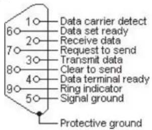
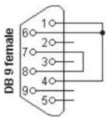
The serial automation port is used to send automation signals to the automation computer using the Sur-Gard Automation protocol. Only the serial port requires RX, TX, and GRD.
| RJ45 Pin no D | Description in relation to SG-System I DB9 | Pin no |
| 1 Not connected 6 | ||
| 2 | C | T |
| 3 | G | R |
| 4 | T | X |
| 5 | R | X |
| 6 | D | C |
| 7 | R | T |
| 8 Not connected Not connected | ||
S
D
D
S


Events & Messages
G
DRL3 Events & Messages
| Message Computer Printer | ||
| Communication Fail - No Signal Send on a Call 001001[#0000|NYCssSS](Where ss is shelf # and SS is slot #) | SG -01-001-0000--COMMUNICATION FAIL | |
| Invalid Report - Bad Signal Send on a Call 001001[#0000|NYNssSS](Where ss is shelf # and SS is slot #) | SG -01-001-0000--INVALID REPORT | |
| Phone Line Trouble 001001[#0000|NLTssSS] | (Ghere ss is shelf # and SS is slot #) | SG -01-001-0000--PHONE LINE TROUBLE |
| Phone Line Trouble Restoral 001001[#0000|NLRssSS] | (Where ss is shelf # and SS is slot #) | SG -01-001-0000--PHONE LINE RESTORAL |
| Phone Line 2 Trouble 001001[#0000|NLTssSS] | (Where ss is shelf # and SS is slot #) | SG -01-001-0000--PHONE LINE 2 TROUBLE |
| Phone Line 2 Trouble Restoral 001001[#0000|NLRssSS] | (Where ss is shelf # and SS is slot #) | SG -01-001-0000--PHONE LINE 2 RESTORAL |
| Call has been Blocked by AIIS 012345[#0000|ABLOCKEDCALL 123459056601075] | SG -12-345-0000--BLOCKED CALL 9056601075 12345 | |
| DSP Fault - Incorrect DSP on Power UP 001001[#0000|NYFssSS](Where ss is shelf # and SS is slot #) | SG -01-001-0000--DSP FAULT | |
| DRL-Online Timeout -Timer Expires 001001[#0000|NSsSS](Where ss is shelf # and SS is slot #) | SG -01-001-0000--DRL ON-LINE TIMEOUT | |
| Audio Initiated S01001[#1234|NLFssSS] | (Ghere ss is shelf # and SS is slot #) | SG -01-001-1234--AUDIO INITIATED |
| Audio Cancelled | No Automation Message | SG -01-001-1234--AUDIO CANCELLED |
| Line Card Coldboot No Automation Message SG -01-001-0000--COLDBOOT | ||
| Communication Fail - Fax Received | 001001[#0000|NYCssSS*FAX*(Where ss is shelf # and SS is slot #) | SG -01-002-0000--COMMUNICATION FAIL - FAX |
| Communication Fail - Due to Noise | 001001[#0000|NYCssSS*NOISE*(Where ss is shelf # and SS is slot #) | SG -01-001-0000--COMMUNICATION FAIL - NOISE |
| Option has been changed | 001001[#0000|NLSssSS](Where ss is shelf # and SS is slot #) | SG -01-001-0000--Option Change |
| Internal Communication Error | 001000[#0000|NYOssSS] | SG -01-001-0000--Internal Communication Error35303130303120313831323334453630323333313131 |
| Firmware Update is successful No Automation Message | SG -01-001-0000--LC Programming | |
| Printer Buffer Full | 001001[#0000|NYB0001] | SG -01-001-0000-YB-Printer Buffer Full |
| Computer Buffer Full | 001001[#0000|NYB0002] | SG -01-001-0000-YB-Computer Buffer Full |
| Software Checksum Fail | O01000[#0000|NYF0100] | SG -01-001-0000--Checksum Failed |
G
DRL3IP Events & Messages
| Message Computer Printer | ||
| IP account table has been set by the console application | 001001[#0000|NRB*IP.IP.IP.*] | SG -01-001-0000-RB-Console Account Port Lead In |
| IP account table has been requested by the console application | 001001[#0000|NRS*IP.IP.IP.*] SG -01-001-0000-RS-Console Account Port Lead Out | |
| Transmitter has successful had encryption enabled (where IP is transmitters IP, and X is the transmitters account) | 000001[#XXXXXXXXX|NYZ0010] SG -00-001-XXXXXXXXX-YZ-*ENCRYPTION ENABLED - IP.IP.IP.* | |
| The transmitter is not able to support encryption request (where IP is transmitters IP, and X is the transmitters account) | No Automation message SG -01-001-XXXXXXXXX-*ENCRYPTION NOT SUP-PORTED - IP.IP.IP.* | |
| The transmitter is not able to support encryption request (where IP is transmitters IP, and X is the transmitters account) | No Automation message | |
| Transmitter has not successful had encryption enabled (where IP is transmitters IP, and X is the transmitters account) | 01001[#XXXXXXXXX|NYZ0011] SG -01-003-XXXXXXXXX-YZ-*ENCRYPTION SET FAIL - IP.IP.IP.* | |
| Transmitter has successful had encryption disabled (where IP is transmitters IP, and X is the transmitters account) | 000001[#XXXXXXXXX|NYZ0012] SG -00-001-XXXXXXXXX-YZ-*ENCRYPTION DISABLED - IP.IP.IP.* | |
| Transmitter has been deleted from account table (where X is the transmitters account) | 000001[#XXXXXXXXX|NJX*IP.IP.IP.*] SG -00-001-XXXXXXXXX-JX-*Transmitter Deleted IP.IP.IP.* | |
| Transmitter has been added to Account table (where X is the transmitters account) | 000001[#XXXXXXXXX|NXA*IP.IP.IP.*] SG -00-001-XXXXXXXXX-XA-*Unknown Account IP.IP.IP.* | |
| Transmitter with supervision enabled has turned off supervision (where IP is transmitters IP, and X is the transmitters account) | 001001[#XXXXXXXXX|NYG*IP.IP.IP.*] SG -01-001-XXXXXXXXX-YG-*Transmitter Supervision Disable IP.IP.IP.* | |
| Remote shutdown has been sent to the transmitter. Where:XXXXXXXXX is the account code of the transmitter IP.IP.IP is the current IP address of the transmitter | 000001[#000000001|NYX0001] | SG -00-001-000000001-YX-*TRANSMITTER SHUTDOWN - IP.IP.IP.* |
| Transmitter has not successful completed the shutdown command (where IP is transmitters IP, and X is the transmitters account) | 001001[#XXXXXXXXX|NYX0002 SG -01-001-XXXXXXXXX-YX-*TRANSMITTER SHUT-DOWN FAIL IP.IP.IP.* | |
| Firmware Update | No Automation message | SG -01-001-0000-LC Firmware Update Initiated |
| Firmware Update Failed | No Automation message | SG -00-0FF-0000-LC Firmware Update Failed |
| Transmitter Absent when supervised | 000001[#XXXXXXXXX|NYC*IP.IP.IP.*] | SG -00-001-XXXXXXXXX-YC-*Transmitter Failure IP.IP.IP.* |
| Transmitter Restore for supervised accounts | 000001[#XXXXXXXXX|NYK*IP.IP.IP.*] | SG -00-001-XXXXXXXXX-YK-*Transmitter Restoral IP.IP.IP.* |
| Transmitter Swap When the account change but MAC is the same | 000001[#XXXXXXXXX|NYS*IP.IP.IP.*] | SG -00-001-XXXXXXXXX-YS-*Transmitter Swap IP.IP.IP.* |
| Invalid report when an incorrect signal is sent 000001[#XXXXXXXXX XX|NYN*IP.IP.IP.*] | SG -00-001-XXXXXXXXX-YN-*Invalid Report/Possible Compromise Attempt IP.IP.IP.* | |
| Account Table size has been exceeded | 001001[#XXXXXXXXX|NJO*IP.IP.IP.*] | SG -01-001-XXXXXXXXX-JO-*Maximum Accounts Exceeded IP.IP.IP.* |
| Option Change Message | 001001[#0000|NLS0107] | SG -01-001-0000-LS-Option Change: XX YY |
| Console Session Denied- Incorrect Password | 001000[#0000|NRD0002] | SG -01-000-0000-NRD0002-Console Session Denied |
| Printer Buffer Full | 001001[#0000|NYB0001] | SG -01-001-0000-YB-Printer Buffer Full |
| Computer Buffer Full | 001001[#0000|NYB0002] | SG -01-001-0000-YB-Computer Buffer Full |
| Computer Communication Failure | 001000[#0000|NYOssSS] | SG -01-000-0000-NYOssSS-Computer: Inter-Comm Error |
| Printer Communication Failure | 001000[#0000|NYOssSS] | SG -01-000-0000-NYOssSS-Printer: Inter-Comm Error |
| LC Reset | No Automation message SG -00-0FF-0000-LC RESET by CPM | |
G
| Account table is close to Full | 001001[#0000|NJL*IP.IP.IP*] | SG -01-001-0000-JL-*Account table 75% full IP.IP.IP* |
| Network Fail | 001001[#0000|NNT *IP.IP.IP*] | SG -01-001-0000-NR-Network Failure |
| Network Restore | 001001[#0000|NNR*IP.IP.IP*] | SG -01-001-0000-NR-Network Restoral |
| Line Card Power up | No Automation message | SG -01-001-0000--LC Power Up vx.xx.xx.xxx |
| Possible Compromise Attempt 001001[#XXXXXXXXXX|NPC*IP.IP.IP*](where IP is transmitters IP, and X is the trans-mitters account) | SG -01-001-XXXXXXXXXX-PC-Possible Compromise Attempt | |
| COLDBOOT was performed by Uscr via Dcbug | No Automation message | SG -01-001-0000--LC COLDBOOT by DEBUG |
| COLDBOOT was performed by User via Console/LCD | No Automation message SG -01-001-0000--LC COLDBOOT by CPM | |
| 2-Way Audio Initiated 001001[#XXXXXXXXXX|NLF*#NNNN-NNN...*] | SG -01-001-XXXX-LF-AUDIO CALLBACK INITIATED -XXXXXXXXXXXXXXXXX | |
G
DRL3 2L Events & Messages
| Message Computer Printer | ||
| SG-DRL3 2L Power Up where X.XX.XXX.XXX is the software version information. | 001002[#0000|NRR0101] SG -01-002-0000-NRR0101-SG-DRL3 2L v1.20.01.010 Power Up | |
| Channel 1 Option Change (where XX is the option #, and YY is the new option setting) | 001001[#0000|NLS0101] SG -01-001-0000-NLS0101-Option Change: C1 #XX YY(Where XX= Option # and YY-Value) | |
| Channel 2 Option Change (where XX is the option #, and YY is the new option setting) | 001002[#0000|NLS0101] SG-01-002-0000-NLS0101-Option Change: C2 #XX YY(Where XX= Option # and YY-Value) | |
| Option change from console where C# is the channel changed (1/2 POTS channels) | 001001[#0000|NLS0101 SG -01-001-0000-NLS0101-Option Change: C# #XX 'Y'(Where XX-Option # and "Y" = Value) | |
| Printer Buffer Full (POTS Channel) 001001[#0000|NYB0001] SG -01-001-0000-YB-Printer Buffer Full | ||
| Computer Buffer Full (POTS Channel) | 001001[#0000|NYB0002] | SG -01-001-0000-YB-Computer Buffer Full |
| Software Checksum Fail | O01000[#0000|NYF0100] | SG -01-001-0000--Checksum Failed |
| Call was blocked on channel 1 (not answered) [i] | 001001[#0000|ABLOCKEDCALL 12345 9056601075] | SG -01-001-0000--BLOCKED CALL 9056601075 12345 |
| Call was blocked on channel 2 (not answered) [ii] | 001129[#0000|ABLOCKEDCALL 12345 9056601075] | SG -01-129-0000--BLOCKED CALL 9056601075 12345 |
| Panel attempted to communicate to the linecard but data was not valid. | 001001[#0000|NYN0101] SG -01-001-0000--INVALID REPORT | |
| Communication Fail Due to No Response from the panel. CH1 | 001001[#0000|NYC0101] SG -01-001-0000--COMMUNICATION FAIL. | |
| Call failed due to detection of fax device on the call - channel 1 | 001001[#0000|NYCssSS*FAX*(Where ss is the shelf # and SS is the slot #) | SG -01-001-0000--COMMUNICATION FAIL - FAX |
| Call failed due to detection of Noise on the call - channel 1 | 001001[#0000|NYC0101*NOISE*] | SG -01-001-0000--COMMUNICATION FAIL - NOISE |
| Communication Fail Due to No Response from the panel. CH2 | 001129[#0000|NYC0101] SG -01-129-0000--COMMUNICATION FAIL | |
| Call failed due to detection of fax device on the call - channel 2 | 001129[#0000|NYCssSS*FAX*(Where ss is the shelf # and SS is the slot #) | SG -01-129-0000--COMMUNICATION FAIL - FAX |
| Call failed due to detection of Noise on the call - channel 2 | 001129[#0000|NYC0101*NOISE*] | SG -01-129-0000--COMMUNICATION FAIL - NOISE |
| Phone line trouble channel 1. | 001002[#0000|NLTO102] | SG -01-002-0000--PHONE LINE TROUBLE |
| Phone line restore channel 1 primary. | 001002[#0000|NLRO102] | SG -01-002-0000--PHONE LINE RESTORAL |
| Phone line trouble channel 2. | 001129[#0000|NLTO101] | SG -01-129-0000--PHONE LINE 2 TROUBLE |
| Phone line restore channel 2. | 001129[#0000|NLRO101] | SG -01-129-0000--PHONE LINE 2 RESTORAL |
| DSP fault channel 1 | 001001[#0000|NYF0101] | SG -01-001-0000--DSP FAULT |
| DSP fault channel 2 | 001129[#0000|NYF0101] | SG -01-129-0000--DSP FAULT |
| Communication on-line timeout Channel 1 | 001001[#0000|NYS0101] | SG -01-001-0000--DRL ON-LINE TIMEOUT |
| Communication on-line timeout Channel 2 | 001129[#0000|NYS0101] | SG -01-129-0000--DRL ON-LINE TIMEOUT |
| Two Way Audio Initiated - channel 1 - where XXXX is the account code entering two way communication | S01001[#1234|NLF0101] SG -01-001-1234--AUDIO INITIATED | |
| Two Way Audio Initiated - channel 2 - where XXXX is the account code entering two way communication | S01129[#1234|NLF0101] SG -01-129-1234--AUDIO INITIATED | |
| Two Way Audio Cancelled - channel 1 | No Automation message | SG -01-001-1234--AUDIO CANCELLED |
| Two Way Audio Cancelled - channel 2 | No Automation message | SG -01-129-1234--AUDIO CANCELLED |
| COLDBOOT was performed by System | No Automation message | SG -01-001-0000--LC Coldboot by CPM |
| Reset by console | No Automation message | SG -01-001-0000--LC Rcsct by CPM |
| Reset by User | No Automation message | SG -01-001-0000--LC Reset by DEBUG |
| Firmware update has been started via USB port | No Automation message | SG -01-002-0000--LC Firmware Update Initiated (USB) |
G
| Firmware update has failed | No Automation message | SG -01-000-0000--LC Firmware Update Failed |
| GET DNIS Table No Automation message SG -01-002-0000 | --GET DNIS Table | |
| SET DNIS Table No Automation message SG -01-002-0000 | --SET DNIS Table | |
| Line Card Default By Console | No Automation message | SG -01-001-0000--LC Coldboot by CPM |
| Computer Communication Failure | 001000[#0000|NYOssSS] | SG -01-000-0000-NYOssSS-Computer: Inter-Comm Error |
| Printer Communication Failure | 001000[#0000|NYOssSS] | SG -01-000-0000-NYOssSS-Printer: Inter-Comm Error |
G
CPM3 Events & Messages
| Message Computer Printer | ||
| Shelf 1 PSU3 Failure 001000[#0000|NAT0000] SG -01 | -000-0000-NAT0000-PSU 1 Failed | |
| Shelf 1 PSU3 Restoral 001000[#0000|NAR0000] SG -01 | -000-0000-NAR0000-PSU 1 Restored | |
| Shelf 2 PSU3 Failure 001000[#0000|NAT0001] SG -01 | -000-0000-NAT0001-PSU 2 Failed | |
| Shelf 2 PSU3 Restoral 001000[#0000|NAR0001] SG -01 | -000-0000-NAR0001-PSU 2 Restored | |
| PSU3 Inter-Connect Cable Failure 001000[#0000|NAT0100] SG -01 | -000-0000-NAT0100-PSU Cable Failed | |
| PSU3 Inter-Connect Cable Restoral | 001000[#0000|NAR0100] | SG -01-000-0000-NAR0100-PSU Cable Restored |
| DC/DC3 A Shelf 1 Failure | 001000[#0000|NYP0100] | SG -01-000-0000-NYP0100-DCA 1 Failed |
| DC/DC3 A Shelf 1 Restoral 001000[#0000|NYR0100] SG -01 | -000-0000-NYR0100-DCA 1 Restored | |
| DC/DC3 B Shelf 1 Failure | 001000[#0000|NYP0101] | SG -01-000-0000-NYP0101-DCB 1 Failed |
| DC/DC3 B Shelf 1 Restoral | 001000[#0000|NYR0101] | SG -01-000-0000-NYR0101-DCB 1 Restored |
| DC/DC3 A Shelf 2 Failure | 001000[#0000|NYP0200] | SG -01-000-0000-NYP0200-DCA 2 Failed |
| DC/DC3 A Shelf 2 Restoral 001000[#0000|NYR0200] SG -01 | -000-0000-NYR0200-DCA 2 Restored | |
| DC/DC3 B Shelf 2 Failure | 001000[#0000|NYP0201] | SG -01-000-0000-NYP0201-DCB 2 Failed |
| DC/DC3 B Shelf 2 Restoral | 001000[#0000|NYR0201] | SG -01-000-0000-NYR0201-DCB 2 Restored |
| Fan Circuit Shelf 1 Failure 001000[#0000|NYX0100] SG -01 | -000-0000-NYX0100-Fan Circuit 1 Failed | |
| Fan Circuit Shelf 1 Restoral Fan | 001000[#0000|NYZ0100] | SG -01-000-0000-NYZ0100-Fan Circuit 1 Restored |
| Fan Circuit Shelf 2 Failure Fan | 001000[#0000|NYX0200] | SG -01-000-0000-NYX0200-Fan Circuit 2 Failed |
| Fan Circuit Shelf 2 Restoral Fan | 001000[#0000|NYZ0200] | SG -01-000-0000-NYZ0200-Fan Circuit 2 Restored |
| TCP/IP Shelf 1 Printer Failure | 001000[#0000|NVZ0100] | SG -01-000-0000-NVZ0100-TCP/IP 1 Printer Failed |
| TCP/IP Shelf 1 Printer Restoral | 001000[#0000|NVY0100] | SG -01-000-0000-NVY0100-TCP/IP 1 Printer Restored |
| TCP/IP Shelf 2 Printer Failure | 001000[#0000|NVZ0200] | SG -01-000-0000-NVZ0200-TCP/IP 2 Printer Failed |
| TCP/IP Shelf 2 Printer Restoral | 001000[#0000|NVY0200] | SG -01-000-0000-NVY0200-TCP/IP 2 Printer Restored |
| Parallel Shelf 1 Printer Failure | 001000[#0000|NVZ0101] | SG -01-000-0000-NVZ0101-Parallel 1 Printer Failed |
| Parallel Shelf 1 Printer Restoral | 001000[#0000|NVY0101] | SG -01-000-0000-NVY0101-Parallel 1 Printer Restored |
| Parallel Shelf 2 Printer Failure | 001000[#0000|NVZ0201] | SG -01-000-0000-NVZ0201-Parallel 2 Printer Failed |
| Parallel Shelf 2 Printer Restoral | 001000[#0000|NVY0201] | SG -01-000-0000-NVY0201-Parallel 2 Printer Restored |
| Serial Shelf 1 Printer Failure | 001000[#0000|NVZ0102] | SG -01-000-0000-NVZ0102-Serial 1 printer Failed |
| Serial Shelf 1 Printer Restoral | 001000[#0000|NVY0102] | SG -01-000-0000-NVY0102-Serial 1 printer Restored |
| Serial Shelf 2 Printer Failure | 001000[#0000|NVZ0202] | SG -01-000-0000-NVZ0202-Serial 2 printer Failed |
| Serial Shelf 2 Printer Restoral | 001000[#0000|NVY0202] | SG -01-000-0000-NVY0202-Serial 2 printer Restored |
| SG-TCP/IP Shelf 1 Failure | 001000[#0000|NNT0100] | SG -01-000-0000-NNT0100-SG-TCP/IP 1 Failed |
| SG-TCP/IP Shelf 1 Restoral | 001000[#0000|NNR0100] | SG -01-000-0000-NNR0100-SG-TCP/IP 1 Restored |
| SG-TCP/IP Shelf 2 Failure | 001000[#0000|NNT0200] | SG -01-000-0000-NNT0200-SG-TCP/IP 2 Failed |
| SG-TCP/IP Shelf 2 Restoral | 001000[#0000|NNR0200] | SG -01-000-0000-NNR0200-SG-TCP/IP 2 Restored |
| SG-Serial Shelf 1 Failure | 001000[#0000|NYC0101] | SG -01-000-0000-NYC0101-SG-SERIAL 1 Failed |
| SG-Serial Shelf 1 Restoral | 001000[#0000|NYK0101] | SG -01-000-0000-NYK0101-SG-SERIAL 1 Restored |
| SG-Serial Shelf 2 Failure | 001000[#0000|NYC0201] | SG -01-000-0000-NYC0201-SG-SERIAL 2 Failed |
| SG-Serial Shelf 2 Restoral | 001000[#0000|NYK0201] | SG -01-000-0000-NYK0201-SG-SERIAL 2 Restored |
G
| Switch Into Active Mode | 001000[#0000|NSC0003] | SG -01-000-0000-NSC0003-Switching To Active Mode |
| Switch To Manual Mode | 001000[#0000|NSC0000] | SG -01-000-0000-NSC0000-Switching To Manual Mode |
| Switch To Normal Mode 001000[#0000|NSC0003] SG-01-000-0000-NSC0003-Switching To Normal Mode | ||
| Switch To Standby Mode | 001000[#0000|NSC0002] | SG -01-000-0000-NSC0002-Switching To Standby Mode |
| Line Card Absent 001000[#0000|NYDssSS] | (Where ss=Shelf and SS=Slot) | SG -01-000-0000-NYDssSS-Line Card Absent (Where ss=Shelf and SS=Slot) |
| Line Card Restored 001000[#0000 NYEssSS] | (Where ss=Shelf and SS=Slot) | SG -01-000-0000-NYEssSS-Line Card Restored (Where ss=Shelf and SS=Slot) |
| Internal Communication Error (Computer) | 001000[#0000|NYOss00] | SG-01-000-0000-NYOss00-Computer: Inter-Comm. Error |
| Internal Communication Error (Printer) | 001000[#0000|NYOss00] | SG-01-000-0000-NYOss00-Printer: Inter-Comm. Error |
| Internal Communication Error (Console) | 001000[#0000|NYOss00] | SG-01-000-0000-NYOss00-Consolc: Inter-Comm. Error |
| Primary CPM3 Failure | 001000[#0000|NYX0001] | SG -01-000-0000-NYX0001-Primary CPM3 Failure |
| Primary CPM3 Restoral | 001000[#0000|NRR0001] | SG -01-000-0000-NRR0001-Primary CPM3 Restore |
| Secondary CPM3 Failure | 001000[#0000|NYX0002] | SG -01-000-0000-NYX0002-Secondary CPM3 Failure |
| Secondary CPM3 Restoral | 001000[#0000|NRR0002] | SG -01-000-0000-NRR0002-Secondary CPM3 Restore |
| Shelf 1 UPS AC Fail (PGM In) | 001000[#0000|NAT0102] | SG -01-000-0000-NAT0102-UPS AC 1 Failed |
| Shelf 1 UPS AC Restored 001000[#0000|NAR0102] SG -01-000-0000-NAR0102-UPS AC 1 Restored | ||
| Shelf 1 UPS Low Battery Restore | 001000[#0000|NYR0102] | SG -01-000-0000-NYR0102-UPS Battery 1 Restored |
| Shelf 1 UPS Low Battery | 001000[#0000|NYT0102] | SG -01-000-0000-NYT0102-UPS Battery 1 Low |
| Shelf 1 PSC Failure | 001000[#0000|NAT0002] | SG-01-000-0000-NAT0002-PSC 1 Failed |
| Shelf 1 PSC Restoral | 001000[#0000|NAR0002] | SG-01-000-0000-NAR0002-PSC 1 Restored |
| Shelf 2 PSC Failure | 001000[#0000|NAT0003] | SG -01-000-0000-NAT0003-PSC 2 Failed |
| Shelf 2 PSC Restoral | 001000[#0000|NAR0003] | SG-01-000-0000-NAR0003-PSC 2 Restored |
| Shelf 2 UPS AC Fail (PGM In) | 001000[#0000|NAT0202] | SG -01-000-0000-NAT0202-UPS AC 2 Failed |
| Shelf 2 UPS AC Restored | 001000[#0000|NAR0202] | SG -01-000-0000-NAR0202-UPS AC 2 Restored |
| Shelf 2 UPS Low Battery Restore | 001000[#0000|NYR0202] | SG -01-000-0000-NYR0202-UPS Battery 2 Restored |
| Shelf 2 UPS Low Battery (PGM in) | 001000[#0000|NYT0202] | SG -01-000-0000-NYT0202-UPS Battery 2 Low |
| Console Session Denied CPM3 Primary | 001000[#0000|NRD0001] | SG -01-000-0000-NRD0001-Console Session Denied |
| Console Session Denied CPM3 Secondary | 001000[#0000|NRD0002] | SG -01-000-0000-NRD0002-Console Session Denied |
| Option Change | 001000[#0000|NLS0101] | SG -01-000-0000-NLS0101-Option Change: C0 |
| Automation Time & Date Update Failed | 001000[#0000|NRU0000] | SG-01-000-0000-NRU0000-Time&Date Update Fail |
| AHS Database Full | No Automation Message | SG-01-000-0000--CPM AHS Database Full |
| Resct fallback | 001000[#0000|NYY0000] | SG -01-000-0000-NYY0000-Reset SG-Fallback Initiated |
| SG-CPM3 Power Up where X.XX.XXX.XXX is the software version information. (System III only) -Primary | 001000[#0000|NRR0001] SG -01-000-0000-NRR | 0001-Primary CPM3 v2.02.01.001 Power Up |
| SG-CPM3 Power Up where X.XX.XXX.XXX is the software version information. (System III only) -Secondary | 001000[#0000|NRR0002] SG -01-000-0000-NRR | 0002-Secondary CPM3 v2.02.01.001 Power Up |
| License key entered is incorrect | No Automation Message | SG -01-000-0000--Invalid License Key |
| Get AHS Table | No Automation Message | SG -01-000-0000--GET AHS Table |
| SET AHS TABLE | No Automation Message | SG -01-000-0000--SET AHS Table |
| AHS FLASH START(ACTIVE CPM) | No Automation Message | SG -01-000-0000--AHS Flash Start (ACTIVE) |
| AHS FLASH START(STANDBY CPM) | No Automation Message | SG -01-000-0000--AHS Flash Start (STANDBY) |
G
| AHS FLASH DONE(ACTIVE CPM) | No Automation Message | SG -01-000-0000--AHS Flash Done (ACTIVE) |
| AIIS FLASII DONE(STANDBY CPM) | No Automation Message | SG -01-000-0000--AIIS Flash Done (STANDBY) |
| RESET BY CONSOLF No Automation Message SG -01-000-0000--RESET by CONSOLF | ||
| Invalid Password to Enter LCD Program | 001000[//0000|NLX0000] | SG -01-000-0000-NLX0000-User:0 Local Programming Dcnicd |
| Local Programming Begin via LCD | 001000[#0000|NLB0000] | SG -01-000-0000-NLB0000-User:0 Local Programming Begins |
| Local Programming End via LCD | 001000[#0000|NLD0000] | SG -01-000-0000-NLD0000-User:0 Local Programming Ended |
| Manual Mode Message Ack By User | No Automation Message | SG -01-000-0000--01/00-0000-NSC0000-Switching To Manual Mode-Acknowledged by User 0 |

H
Glossary
H
| Account | The portion of a signal which contains the information identifying the location or the owner of the alarm panel. Also referred to as account number, account code or account digits. |
| Acknowledgement (ACK) | A signal sent from the receiver to the panel indicating that data has been received. A positive acknowledgement (ACK) means data was received without any detected errors. (see kiss-off). A negative acknowledgement (NAK) means data was received, but there were detected errors. An acknowledgement may be sent per packet or per alarm. |
| AHS | Automatic Handshake Selection. Refers to the receiver feature which enables the line card to request the handshake to be used with a particular panel from the CPM. The CPM maintains a database of most recently used handshakes for all accounts connected to the receiver. Handshakes are stored along with the phone number of the associated alarm panel. |
| Alarm | A message transmitted from the panel to the receiver containing account, event, zone, user or other information. There may be one or more per call. An alarm may be repeated in the same call (if not successfully delivered in a previous attempt). An alarm will contain one or more packets. Packets can contain rounds or different information. Alarm transmission is initiated with a handshake and, if received correctly, acknowledged with a kiss-off. |
ANI Automatic Number Identification.
| ASCII | America Standard Code for Informational Interchange. A seven-bit alphanumeric code used extensively in data communications. Parity is often added to the seven-bit code for error detection. |
| Automation | The combination of software package and PC which connects to the receiver to receive alarm events. The automation can be connected either by direct serial connection or TCP. |
| Automation Message | The alarm information delivered by a receiver in a specified protocol to a central station computer or network. Also referred to as a computer message |
| Backplane See SG-BP3X. | |
| Block | A group of data that specifically makes up one of the elements of an alarm. For example: account block, event block, or alarm block. One packet could contain multiple blocks. |
| Busy Out | A state of a line card. Under predefined criteria the line card will go off-hook so as to not process any new alarms. |
| Call | The process of a receiver going off-hook, receiving one or more alarms and returning on-hook. |
| Caller ID | An FSK format received by the line card. This format can be received prior to sending the handshakes. The Caller ID data can be used by the receiver to provide additional information to all alarms received during a call. |
| Capture | The ability of a receiver to store commands sent to the panel from the automation computer after all of the alarms have been sent from the panel to the receiver. |
| Centronics | A parallel printer interface standard. Also known as standard IEEE1284. A centronics interface is implemented on the SG-CPM3 (through the backplane) to interface to the local parallel printer. |
| Checksum | Additional data added to an alarm indicating whether the contents have been received correctly. This is generally done by summing all the digits in the message (mod 256) and reporting this as the checksum. Different methods of calculating a checksum may be specified in particular formats or protocols. |
| C.L.A.S.S. | Custom Local Area Signaling Services. This term is used in the telephone industry to represent all features of a telephone line, such as Caller -ID, Call Forwarding, 3-Way Calling etc. |
H
Client One side of a 2-sided TCP socket connection. The client is the one responsible for initiating the socket connection with the remote host (the server). The console represents the client side of the socket connection with the SG-CPM3.
Computer Message See Automation Message.
Console A PC application program which can connect to the receiver and provide diagnostic/programming abilities to the user. For the SG-System III, the console connects to the SG-CPM3 via TCP/IP. Visit the Tyco website (www.tyco.com) for the latest version.
Dialer Another name for a control panel.
DNIS Dialed Number Identification Service.
DTMF Dual Tone Multiple Frequency. A method of dialing which utilizes 2 sets of 4 tones (frequencies) each. Selecting one tone from each set will produce 16 distinct pairs. These pairs are used to dial digits when dialing a telephone number.
Ethernet A network protocol which encompasses the lowest logical layer of the network stack, immediately above the physical layer. This protocol is governed by the IEEE and is outlined in the IEEE802.3 specification. Ethernet consists of several variations, including 10Base2, 10Base5, 10BaseT, 100BaseT, and others. 10BaseT and 100BaseT are the most prevalent.
Equivalent Line Number An option in the receiver. By default printer and computer messages will contain the line card number. Sometimes it is necessary to output the printer and computer messages with a different line card number; in this case this option can be used to overwrite the line card number in the printer and computer outputs of the receiver.
Event The specific type of alarm being reported by the panel.
Event Code A term used to describe a character or group of characters in an automation output. This character(s) is used to represent the event that was reported by the panel. Example 1: Sur-Gard automation reports an alarm event using an event code of 'A', Restore as 'R', or Trouble as 'T'. Example 2: Sur-Gard automation reports using a SIA output for a burglary alarm using an event code of 'BA'.
FES Format Expert Systems. The name given to a receiver task which performs the basic functions of: 1. sending handshakes; 2. detecting the format from the panel; 3. processing the alarm from the panel; 4. sending a kiss-off to the panel.
Format The pre-established order of events and meanings of the various characters in an alarm transmitted from a panel to a receiver.
FSK Frequency Shift Keying. A modulation technique used with low-speed modems (300 to 1800 bps). The carrier frequency is shifted between two discrete frequencies in accordance with the binary serial data.
Handshake A signal sent by the receiver to a panel indicating that a connection has been established. These are either tones or modem data.
Heartbeat A periodic signal sent from the automation outputter tasks to the automation software to verify the presence of that output. The period of this heartbeat is controlled via an option in the SG-CPM3. Alternatively, the heartbeat refers to the signal sent between SG-CPM3s to verify the presence/absence of each other.
Hook Flash The process of the receiver going temporarily off-hook, usually in an attempt to transfer the phone call.
Hot-Swappable Refers to the ability to add or remove particular cards to or from the system without removing power. In the SG-System III, the SG-CPM3, SG-DRL3, SG-DC/DC3 and SG-PSC3 are all fully hot-swappable.
H
HTTP Hypertext Transfer Protocol. A higher level protocol within the TCP/IP suite of protocols which is responsible for implementing web browsers. This is the protocol implemented by the SG-CPM3 to enable the web interface to function.
IEEE 1284 See Centronics.
IEEE 802.3 See Ethernet.
Inter-burst Time A term for the reception of pulse formats. The time between two bursts.
Inter-digit Time A term used for reception of pulse or DTMF formats. The time between two digits.
Internal Trouble A trouble condition which is generated inside a receiver, as opposed to being sent as an alarm from the panel. Internal troubles are also sent to the printer and automation outputs.
Kiss-off A term used in the security industry for a positive acknowledgement.
Line An individual channel on a line card. Equivalent to 1 telephone line.
Line Card A removable, hot-swappable card which contains a POTS line interface which controls 1 or more POTS lines. For SG-System III, each line card (SG-DRL3) will interface to 1 line.
Line Conditioning Electrical compensation for attenuation and phase delay distortion exhibited by the PSTN. Conditioning is performed through the use of an equalizer.
MAC Address Media Access Control. A globally unique device 6-byte address which identifies a device attached to an Ethernet network.
Assignment of MAC addresses is governed by the IEEE; any OEM company which manufactures Ethernet devices must apply for and purchase an OUI (Organizationally Unique Identifier), which consists of a block of 16,777,216 MAC addresses, all of which have the same first 3 bytes. Subsequent allocation of addresses within that block is at the discretion of the purchaser. Each Ethernet device produced must be programmed with a different MAC address in order to guarantee that each device will function correctly on the network. For the SG-System III, the MAC address is stored in serial EEPROM on the SG-CPM3 board. It is only programmable during manufacturing.
MPC860 The Power PC microprocessor used as the main processor on the SG-CPM3 board.
Multidrop A communication link in which a single channel is shared by several stations or nodes (DVACS is a Multidrop network). Only one station may transmit at a time. Multidrop is also referred to as multipoint.
Negative Acknowledgement (NAK) See acknowledgement.
Off-Hook The process of connecting to the telephone line to answer an incoming call or dial a remote device (answering).
On-Hook The process of releasing the telephone line after completion of a call (hanging up).
Options A set of user-configurable parameters which controls the operation of a device. In the SG-System III, both the SG-DRL3 and the SG-CPM3 contain sets of options. Static options are affect all Profiles on a card. Dynamic options are unique to each profile.
Packet A group of digits or characters of information in an alarm.
Panel A device (the alarm system) at the protected premises used to transmit alarms to the receiver.
H
| Ping | A standard network command which can be used to verify the presence of a device on a network, using the device IP address. Ping is implemented as part of the ICMP protocol and consists of the Echo Request and Echo Reply commands (poll and response respectively). |
| POTS | Plain Old Telephone System. An acronym used to describe a standard analog telephone network, or alternatively a standard analog telephone line. |
| Printer Message | The alarm information delivered by a receiver to a central station printer. This information is generally encapsulated in a descriptive English text message. |
| Profile | Generally refers to a group of options. The receiver can select a "profile" based on certain conditions. |
| Protocol | The pre-established order of events and meanings of the various characters in the information transmitted from a receiver to a monitoring computer. |
| PSTN Public Switched Telephone Network. Analogous to POTS. | |
| Receiver | The equipment used to receive alarms sent from panels. Sur-Gard's receivers are the SLR and the MLR. 'Receiver' is sometimes used interchangeably with 'line card' as it is the line card which actually receives the alarm in the MLR. |
| Ring | One of the wires used on a phone line. By convention this is red. |
| Rounds | Two or more packets of alarm information used for error checking. If two packets (rounds) are identical the packet contains valid data. |
| RRLLL | The part of the automation message which stores the receiver number and line card number. The length of this field is variable and is controlled via an option in both the line card and the SG-CPM3. |
| RS-232 | An asynchronous, point-to-point serial communications protocol. Used to communicate between the SG-DRL3 and a PC for the SG-DRL3's debug output. Also used to communicate between the SG-CPM3 and the automation computer, and the SG-CPM3 and a PC for the SG-CPM3's debug output. |
| Server | One side of a 2-sided TCP socket connection. The server is the one responsible for receiving the socket connection with the remote host (the client). In general, a host which acts as a server can receive multiple client socket connection requests simultaneously. The SG-CPM3 acts as a server to both the console and the web interface. |
| SG | Sur-Gard, a brand name of DSC. Also used to describe a particular type of automation output. |
| SG-BP3 | A motherboard-style PCB which acts as the backbone for a single shelf of a SG-System III receiver. The SG-BP3 contains sockets to which up to 12 SG-DRL3s, 1 SG-CPM3, 1 SG-PSC3 and 2 SG-DC/DC3s can be connected. Furthermore, 2 SG-BP3s can be connected together to form a 2-shelf configuration for the SG-System III receiver. The SG-BP3 also contains connections for a parallel printer and 2 serial automation COM ports, as well as an Ethernet connection. Also referred to as a backplane. |
| SG-BP3X | Rack mount module that converts 50 pin telco connections to 24 individual RJ11 connections. |
| SG-CPM3 | Central Processing Module. The SG-CPM3 controls the overall operation of the SG-System III receiver, which includes multiplexing alarm signals from the line cards and sending them to the appropriate outputs. |
| SG-DC/DC3 | The DC power supply of the SG-System III receiver. |
| SG-DRL3 | POTS Receiver Line Card. |
| SG-DRL3E | Updated DRL3 platform based on the DRL3-2L. |
| SG-DRL3-IP | IP based line card. |
H
SG-DRL3-2L Dual POTS Line Digital Receiver Line Card.
SG-MLRF3 The metal rack which is used to enclose all other modules within a single shelf of the SG-System III receiver.
SG-PSC3 Power Supply Controller.
SG-PSU3 Power Supply Unit.
SG-System III Name given to a single entire receiver configuration, including rack, SG-CPM3(s), line card(s), power supply, etc.
SG-UIB3 User Interface Board. An L-shaped board which connects to the SG-CPM3 and contains output LEDs and 4 push buttons used for the user interface. This board also connects directly to the LCD screen.
SIA Security Industry Association. Sometimes referred to as the SIA format which is an example of FSK modulation.
TCP/IP Transmission Control Protocol/Internet Protocol. A standard network communications protocol. On the SG-System III, TCP/IP is used to communicate between the console and the SG-CPM3. It is also used to connect the SG-CPM3 to a TCP printer (resident on the console) and TCP automation software (runs independent of the console).
Tip One of the wires used on a phone line. By convention this is green.
Zone The portion of an alarm which contains the information identifying the specific zone of the panel that has been violated.
IMPORTANT - READ CAREFULLY:
DSC Software purchased with or without Products and Components is copyrighted and is purchased under the following license terms:
- This End-User License Agreement (“EULA”) is a legal agreement between You (the company, individual or entity who acquired the Software and any related Hardware) and Digital Security Controls, a division of Tyco Safety Products Canada Ltd. (“DSC”), the manufacturer of the integrated security systems and the developer of the software and any related products or components (“HARDWARE”) which You acquired.
- If the DSC software product (“SOFTWARE PRODUCT” or “SOFTWARE”) is intended to be accompanied by HARDWARE, and is NOT accompanied by new HARDWARE. You may not use, copy or install the SOFTWARE PRODUCT. The SOFTWARE PRODUCT includes computer software, and may include associated media, printed materials, and “online” or electronic documentation.
- Any software provided along with the SOFTWARE PRODUCT that is associated with a separate end-user license agreement is licensed to You under the terms of that license agreement.
- By installing, copying, downloading, storing, accessing or otherwise using the SOFTWARE PRODUCT, You agree unconditionally to be bound by the terms of this EULA, even if this EULA is deemed to be a modification of any previous arrangement or contract. If You do not agree to the terms of this EULA, DSC is unwilling to license the SOFTWARE PRODUCT to You, and You have no right to use it.
SOFTWARE PRODUCT LICENSE
The SOFTWARE PRODUCT is protected by copyright laws and international copyright treaties, as well as other intellectual property laws and treaties. The SOFTWARE PRODUCT is licensed, not sold.
- GRANT OF LICENSE This EULA grants You the following rights:
(a) Software Installation and Use - For each license You acquire, You may have only one copy of the SOFTWARE PRODUCT installed.
(b) Storage/Network Usc - The SOFTWARE PRODUCT may not be installed, accessed, displayed, run, shared or used concurrently on or from different computers, including a workstation, terminal or other digital electronic device ("Device"). In other words, if You have several workstations, You will have to acquire a license for each workstation where the SOFTWARE will be used.
(c) Backup Copy - You may make back-up copies of the SOFTWARE PRODUCT, but You may only have one copy per license installed at any given time. You may use the back-up copy solely for archival purposes. Except as expressly provided in this EULA, You may not otherwise make copies of the SOFTWARE PRODUCT, including the printed materials accompanying the SOFTWARE.
- DESCRIPTION OF OTHER RIGHTS AND LIMITATIONS
(a) Limitations on Reverse Engineering, Decompilation and Disassembly - You may not reverse engineer, decompile, or disassemble the SOFTWARE PRODUCT, except and only to the extent that such activity is expressly permitted by applicable law notwithstanding this limitation. You may not make any changes or modifications to the Software, without the written permission of an officer of DSC. You may not remove any proprietary notices, marks or labels from the Software Product. You shall institute reasonable measures to ensure compliance with the terms and conditions of this EULA.
(b) Separation of Components - The SOFTWARE PRODUCT is licensed as a single product. Its component parts may not be separated for use on more than one HARDWARE unit.
(c) Single INTEGRATED PRODUCT - If You acquired this SOFTWARE with HARDWARE, then the SOFTWARE PRODUCT is licensed with the HARDWARE as a single integrated product. In this case, the SOFTWARE PRODUCT may only be used with the HARDWARE as set forth in this EULA..
(d) Rental - You may not rent, lease or lend the SOFTWARE PRODUCT. You may not make it available to others or post it on a server or web site.
(c) Software Product Transfer - You may transfer all of Your rights under this EULA only as part of a permanent sale or transfer of the HARDWARE, provided You retain no copies. You transfer all of the SOFTWARE PRODUCT (including all component parts, the media and printed materials, any upgrades and this EULA), and provided the recipient agrees to the terms of this EULA. If the SOFTWARE PRODUCT is an upgrade, any transfer must also include all prior versions of the SOFTWARE PRODUCT.
(f) Termination - Without prejudice to any other rights, DSC may terminate this EULA if You fail to comply with the terms and conditions of this EULA. In such event, You must destroy all copies of the SOFTWARE PRODUCT and all of its component parts.
(g) Trademarks - This EULA does not grant You any rights in connection with any trademarks or service marks of DSC or its suppliers.
-
COPYRIGHT - All title and intellectual property rights in and to the SOFTWARE PRODUCT (including but not limited to any images, photographs, and text incorporated into the SOFTWARE PRODUCT), the accompanying printed materials, and any copies of the SOFTWARE PRODUCT, are owned by DSC or its suppliers. You may not copy the printed materials accompanying the SOFTWARE PRODUCT. All title and intellectual property rights in and to the content which may be accessed through use of the SOFTWARE PRODUCT are the property of the respective content owner and may be protected by applicable copyright or other intellectual property laws and treaties. This EULA grants You no rights to use such content. All rights not expressly granted under this EULA are reserved by DSC and its suppliers.
-
EXPORT RESTRICTIONS - You agree that You will not export or re-export the SOFTWARE PRODUCT to any country, person, or entity subject to Canadian export restrictions.
-
CHOICE OF LAW - This Software License Agreement is governed by the laws of the Province of Ontario, Canada.
-
ARBITRATION - All disputes arising in connection with this Agreement shall be determined by final and binding arbitration in accordance with the Arbitration Act, and the parties agree to be bound by the arbitrator's decision. The place of arbitration shall be Toronto, Canada, and the language of the arbitration shall be English.
7. LIMITED WARRANTY
(a) NO WARRANTY - DSC PROVIDES THE SOFTWARE "AS I WARRANTY, DSC DOES NOT WARRANT THAT THE SOFTWARE WILL MEET YOUR REQUIREMENTS OR THAT OPERATION OF THE SOFTWARE WILL BE UNINTERRUPTED OR ERROR-FREE.
(b) CHANGES IN OPERATING ENVIRONMENT - DSC shall not be responsible for problems caused by changes in the operating characteristics of the HARDWARE, or for problems in the interaction of the SOFTWARE PRODUCT with non-DSC-SOFTWARE or HARDWARE PRODUCTS.
(c) LIMITATION OF LIABILITY; WARRANTY REFLECTS ALLOCATION OF RISK - IN ANY EVENT, IF ANY STATUTE IMPLIES WARRANTIES OR CONDITIONS NOT STATED IN THIS LICENSE AGREEMENT, DSC'S ENTIRE LIABILITY UNDER ANY PROVISION OF THIS LICENSE AGREEMENT SHALL BE LIMITED TO THE GREATER OF THE AMOUNT ACTUALLY PAID BY YOU TO LICENSE THE SOFTWARE PRODUCT AND FIVE CANADIAN DOLLARS (CAD\$5.00). BECAUSE SOME JURISDICTIONS DO NOT ALLOW THE EXCLUSION OR LIMITATION OF LIABILITY FOR CONSEQUENTIAL OR INCIDENTAL DAMAGES, THE ABOVE LIMITATION MAY NOT APPLY TO YOU.
(d) DISCLAIMER OF WARRANTIES - THIS WARRANTY CONTAINS THE ENTIRE WARRANTY AND SHALL BE IN LIEU OF ANY AND ALL OTHER WARRANTIES, WHETHER EXPRESSED OR IMPLIED (INCLUDING ALL IMPLIED WARRANTIES OF MERCHANTABILITY OR FITNESS FOR A PARTICULAR PURPOSE) AND OF ALL OTHER OBLIGATIONS OR LIABILITIES ON THE PART OF DSC. DSC MAKES NO OTHER WARRANTIES. DSC NEITHER ASSUMES NOR AUTHORIZES ANY OTHER PERSON PURPORTING TO ACT ON ITS BEHALF TO MODIFY OR TO CHANGE THIS WARRANTY, NOR TO ASSUME FOR IT ANY OTHER WARRANTY OR LIABILITY CONCERNING THIS SOFTWARE PRODUCT.
(e) EXCLUSIVE REMEDY AND LIMITATION OF WARRANTY - UNDER NO CIRCUMSTANCES SHALL DSC BE LIABLE FOR ANY SPECIAL, INCIDENTAL, CONSEQUENTIAL OR INDIRECT DAMAGES BASED UPON BREACH OF WARRANTY, BREACH OF CONTRACT, NEGLIGENCE, STRICT LIABILITY, OR ANY OTHER LEGAL THEORY. SUCH DAMAGES INCLUDE, BUT ARE NOT LIMITED TO, LOSS OF PROFITS, LOSS OF THE SOFTWARE PRODUCT OR ANY ASSOCIATED EQUIPMENT, COST OF CAPITAL, COST OF SUBSTITUTE OR REPLACEMENT EQUIPMENT, FACILITIES OR SERVICES, DOWN TIME, PURCHASERS TIME, THE CLAIMS OF THIRD PARTIES, INCLUDING CUSTOMERS, AND INJURY TO PROPERTY. WARNING: DSC recommends that the entire system be completely tested on a regular basis. However, despite frequent testing, and due to, but not limited to, criminal tampering or electrical disruption, it is possible for this SOFTWARE PRODUCT to fail to perform as expected.
FCC Compliance Statement
CAUTION: Changes or modifications not expressly approved by Digital Security Controls could void your authority to use this equipment.
This equipment has been tested and found to comply with the limits for a Class B digital device, pursuant to Part 15 of the FCC Rules. These limits are designed to provide reasonable protection against harmful interference in a residential installation. This equipment generates, uses and can radiate radio frequency energy and, if not installed and used in accordance with the instructions, may cause harmful interference to radio communications. However, there is no guarantee that interference will not occur in a particular installation. If this equipment does cause harmful interference to radio or television reception, which can be determined by turning the equipment off and on, the user is encouraged to try to correct the interference by one or more of the following measures:
• Re-orient the receiving antenna.
- Increase the separation between the equipment and receiver.
- Connect the equipment into an outlet on a circuit different from that to which the receiver is connected.
- Consult the dealer or an experienced radio/television technician for help.
The user may find the following booklet prepared by the FCC useful: "How to Identify and Resolve Radio/Television Interference Problems". This booklet is available from the U.S. Government Printing Office, Washington D.C. 20402, Stock # 004-000-00345-4.
Important Information
This equipment complies with Part 68 of the FCC Rules and the requirements adopted by the ACTA. On the side of this equipment is a label that contains, among other information, a product identifier in the format US:AAAEQ##TXXXX. If requested, this number must be provided to the Telephone Company.
SG-DRL3 Line Card
Product Identifier: US:F53AL03BSYSTEMIII
SG-DRL3-2L Line Card
Product Identifier: US:F53AL02BDRL342L
SG-DRL3E/SG-DRL3E-2L Line Card
Product Identifier: US:F53AL01BDRL34E2L
USOC Jack: RJ-21X
Telephone Connection Requirements
A plug and jack used to connect this equipment to the premises wiring and telephone network must comply with the applicable FCC Part 68 rules and requirements adopted by the ACTA. A compliant telephone cord and modular plug is provided with this product. It is designed to be connected to a compatible modular jack that is also compliant. See installation instructions for details.
Ringer Equivalence Number (REN) The REN is used to determine the number of devices that may be connected to a telephone line. Excessive RENs on a telephone line may result in the devices not ringing in response to an incoming call. In most but not all arcs, the sum of RENs should not exceed five (5.0). To be certain of the number of devices that may be connected to a line, as determined by the total RENs, contact the local Telephone Company. For products approved after July 23, 2001, the REN for this product is part of the product identifier that has the format.
US: AAAEQ##TXXXX. The digits represented by ## are the REN without a decimal point (e.g., 03 is a REN of 0.3). For earlier products, the REN is separately shown on the label.
Incidence of Harm If this equipment SG-SYSTEM III causes harm to the telephone network, the telephone company will notify you in advance that temporary discontinuance of service may be required. But if advance notice is not practical, the Telephone Company will notify the customer as soon as possible. Also, you will be advised of your right to file a complaint with the FCC if you believe it is necessary.
Changes in Telephone Company Equipment or Facilities The Telephone Company may make changes in its facilities, equipment, operations or procedures that could affect the operation of the equipment. If this happens the Telephone Company will provide advance notice in order for you to make necessary modifications to maintain uninterrupted service.
Equipment Maintenance Facility If trouble is experienced with this equipment SG-SYSTEM III, for repair or warranty information, please contact the facility indicated below. If the equipment is causing harm to the telephone network, the Telephone Company may request that you disconnect the equipment until the problem is solved. This equipment is of a type that is not intended to be repaired by the end user.
DSC c/o APL Logistics
757 Douglas Hill Rd
Lithia Springs, GA, 30122 U.S.A.
Additional Information Connection to party line service is subject to state tariffs. Contact the state public utility commission, public service commission or corporation commission for information.
Alarm dialing equipment must be able to seize the telephone line and place a call in an emer-
gency situation. It must be able to do this even if other equipment (telephone, answering system, computer modem, etc.) already has the telephone line in use. To do so, alarm dialing equipment must be connected to a properly installed RJ31X jack that is electrically in series with and ahead of all other equipment attached to the same telephone line. Proper installation is depicted in the figure below. If you have any questions concerning these instructions, you should consult your telephone company or a qualified installer about installing the RJ31X jack and alarm dialing equipment for you.
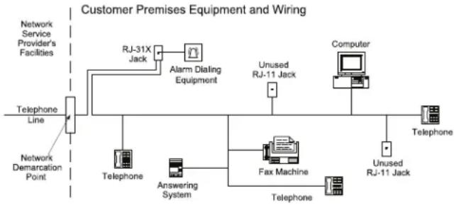
flowchart
graph LR
    A["Telephone Line"] --> B["Network Demarcation Point"]
    B --> C["RJ-31X Jack"]
    C --> D["Alarm Dialing Equipment"]
    D --> E["Unused RJ-11 Jack"]
    E --> F["Computer"]
    F --> G["Unused RJ-11 Jack"]
    G --> H["Telphone"]
    B --> I["Telephone"]
    B --> J["Answering System"]
    J --> K["Fax Machine"]
    K --> L["Telphone"]
    K --> M["Telphone"]
Industry Canada Statement
SG-DRL3 IC:160A-SYSTEM3
SG-DRL3-2L IC:160A-DRL342L
SG-DRL3E/SG-DRL3E-2L IC:160A-DRL34E2L
NOTICE: This equipment meets the applicable Industry Canada Terminal Equipment Technical Specifications. This is confirmed by the registration number. The abbreviation, IC, before the registration number signifies that registration was performed based on a Declaration of Conformity indicating that Industry Canada technical specifications were met. It does not imply that Industry Canada approved the equipment.
NOTICE: The Ringer Equivalence Number (REN) for this terminal is 01 when using line card model SG-DRL3, or 02 when using line card Model SG-DRL3/SG-DRL3E/SG-DRL3E-2L. The REN assigned to each terminal equipment provides an indication of the maximum number of terminals allowed to be connected to a telephone interface. The termination on an interface may consist of any combination of devices subject only to the requirement that the sum of the Ringer Equivalence Numbers of all the devices does not exceed five.
The trademarks, logos, and service marks displayed on this document are registered in the United States [or other countries]. Any misuse of the trademarks is strictly prohibited and Tyco International Ltd. will aggressively enforce its intellectual property rights to the fullest extent of the law, including pursuit of criminal prosecution wherever necessary. All trademarks not owned by Tyco International Ltd. are the property of their respective owners, and are used with permission or allowed under applicable laws.
Product offerings and specifications are subject to change without notice. Actual products may vary from photos. Not all products include all features. Availability varies by region; contact your sales representative.
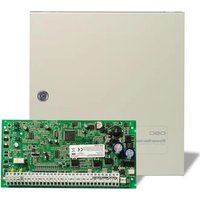


- SG-System III
- Operating Manual
- WARNING Please Read Carefully
- Note to Installers
- System Failures
- • Inadequate Installation
- • Criminal Knowledge
- - Access by Intruders
- • Power Failure
- • Failure of Replaccable Batteries
- • Compromise of Radio Frequency (Wireless) Devices
- - System Users
- • Smoke Detectors
- - Motion Detectors
- - Warning Devices
- - Telephone Lines
- - Insufficient Time
- - Component Failure
- • Inadequate Testing
- • Security and Insurance
- Limited Warranty
- International Warranty
- Warranty Procedure
- Conditions to Void Warranty
- Items Not Covered by Warranty
- Disclaimer of Warranties
- Installer's Lockout
- Out of Warranty Repairs
- GENERAL DESCRIPTION of the EQUIPMENT and CLASSIFICATION.
- CLASSIFICATION
- IMPORTANT:
- CAUTION:
- view of the
- CONNECTION TO THE MAINS
- Introduction
- System Overview
- SG-DRL3/SG-DRL3E/SG-DRL3-2L
- SG-DRL3-IP
- Approvals
- Industry Approvals
- Parallel Printers
- Serial Printers
- UL Manual Mode
- Description (Hardware)
- SG-BP3 Backplane
- SG-PSU3 Power Supply Unit
- Electrical Specifications:
- SG-CPM3 Central Processing Module
- Line Cards
- SG-BP3X Interface Module
- (One required per rack if SG-DRL3, SG-DRL3E, or DRL3-2L are used)
- Receiver Setup and Operation
- Description (Operation)
- Operation with Default Programming
- Virtual Connectivity
- Status Addressing
- Automation Input/Output (Port 1025)
- Compatibility
- Automation Protocols
- Data Byte Protocol
- Acknowledgment of the Signal
- COM Responses
- Automation Absent
- SG-System III SIA Internal Status Output
- SG-CPM3 Operating Modes
- Contrast Adjust
- Active Mode
- Manual Mode
- Standby Mode
- System Trouble and System Information
- AHS Table Management
- 3
- Line Card
- SG-DRL3
- SG-DRL3E
- SG-DRL3-2L
- Line Fault
- SG-CPM3 Error
- SG-DRL3/SG-DRL3E/SG-DRL3-2L Data Reception
- Fault Data Message
- Printer:
- Computer:
- SG-DRL3-IP Fault Data Message
- Ethernet Interface
- Supervised Receiver Database
- Programming/Operation
- Console Software
- Debug
- NOTES:
- Debug Cable Connectivity
- Debug Setup
- Manual Programming
- System Functions
- Reset the SG-CPM3
- Date and Time
- System Information
- Cold Boot Line Card
- Visual Indicator Test
- SG-CPM3 Options
- Option 01: IP Address
- Option 02: Subnet Mask
- Option 08: COM1 Data Bits
- Option 09: COM1 Parity
- Option 0A: Serial Printer Format
- Option 0B: Serial Baud Rate
- Option 0C: Serial Data Bits
- Option 0D: Serial Parity
- Option 0E: AHS Operation Options
- Option 0F: B32 Headers
- Option 10: Input RRLLL Digits
- Option 11: Output RRLLL Digits
- Option 12: Heartbeat Timer
- Option 13: Mute Buzzer
- Option 14: Receiver Number
- Option 15: Printer Test
- Option 16: Mask PSU 1
- NOTE: PSU 1 is the SG-PSU3 installed in shelf 1
- Option 17: Mask PSU 2
- NOTE: PSU 2 is the SG-PSU3 installed in shelf 2
- Option 18: Mask DCA 1
- NOTE: DCA 1 is the SG-DC/DC3 installed in shelf 1.
- Option 19: Mask DCB 1
- NOTE: DCB 1 is the SG-DC/DC3 installed in shelf 1.
- Option 1A: Mask DCA 2
- NOTE: DCA 2 is the SG-DC/DC3 installed in shelf 2.
- Option 1B: Mask DCB 2
- NOTE: DCB 2 is the SG-DC/DC3 installed in shelf 2.
- Option 1E: Mask Fan 1 Fail
- Option 1F: Mask Fan 2 Fail
- Option 20: Mask UPS AC 1
- Option 21: Mask UPS BAT 1
- Option 22: Mask UPS AC 2
- Option 23: Mask UPS BAT 2
- Option 24: Mask SG TCP 1
- Option 25: Mask SG Serial 1
- Option 26: Mask SG TCP 2
- Option 27: Mask SG Serial 2
- Option 28: Mask TCP Printer 1
- Option 29: Mask Parallel Printer 1
- Option 2E: Number of Line Cards
- Option 2F: Automation Mode
- Default (01) Fallback
- First Configuration: Loop (0)
- Second Configuration: Fallback (1)
- Third Configuration: All Mode (2)
- Fourth Configuration: IP Fallback Mode (3)
- Fifth Configuration: Automatic IP SG-Fallback (4)
- Split Shelf Reporting
- Automation Mode Diagrams
- Option 31: ACK Wait
- Option 32: Date Format
- Option 33: Protocol ID
- Option 34: Time Correct
- Option 37 and Option 38: License Key
- Options 3E: RBUS Speed
- 5
- Advanced Programming
- Profiles Introduction
- 1RRLLLssssssAAAAAsYsZZ[DC4]
- 1DDDDDssssssAAAAAsYsZZ[DC4]
- SG-DRL3-2L/DRL3E System Options
- Option 006: Password Menu
- Option 040: Channel Enable
- Option 041: Line card number length
- Option 042: Line card Busy out
- Option 043: Line card Protocol ID
- Option 044: Line card Class Field
- SG-DRL3/SG-DRL3-2L Static Options: 00 - 2F
- SG-DRL3 Option 02: Line Card Number Length
- SG-DRL3 Option 03: Internal messages RS-232
- SG-DRL3 Option 04: 2-Way Audio Activation Time
- SG-DRL3 Option 0C: DTMF Cadence
- SG-DRL3-2L Option 10C/20C: DTMF Cadence
- Example:
- SG-DRL3 Option 0D: Line Conditions
- SG-DRL3-2L Option 10D/20D: Line Conditions
- Examples:
- SG-DRL3/SG-DRL3E Option 0E: Backup Phone Line Option
- SG-DRL3 Option 11: Hook Flash Enable/Disable
- SG-DRL3-2L Option 111/211: Hook Flash Enable/Disable
- SG-DRL3 Option 12: Caller Source ID Option
- SG-DRL3-2L Option 112/212: Caller Source ID Option
- Protocol Format
- SG-DRL3 Option 1F: Debug
- SG-DRL3-2L Option 11F/21F: Debug
- SG-DRL3/SG-DRl3-2L Dynamic Options: 30/130/230 - 3F/13F/23F
- SG-DRL3 Option 71: Library Select
- SG-DRL3-2L Option 171/271: Library Select
- SG-DRL3 Option 72: SIA Option
- SG-DRL3-2L Option 172/272: SIA Option
- Where:
- SG-DRL3 Option 7F: Audio Format Enable
- SG-DRL3-21 Option 17F/27F: Audio Format Enable
- SG-DRL3 Option 80: Kiss-Off to Hang-up Time
- SG-DRL3-2L Option 180/280: Kiss-Off to Hang-up Time
- SG-DRL3 Options 81 through 88: Handshake Selection
- SG-DRL3-2L Options 181/281 through 188/288: Handshake Selection
- SG-DRL3 Option A6: ITI Adjust
- SG-DRL3-2L Option 1A6/2A6: ITI Adjust
- SG-DRL3 Option A7: Silent Knight FSK2 RS-232
- SG-DRL3 Options A8 - AF: Dial-out Number For 2-way Audio Transfer
- SG-DRL3-2L Options 1A8/2A8 - 1AF/2AF: Dial-out Number For 2-way Audio Transfer
- SG-DRL3 Option B1: DMP Area BIN or DEC Option
- SG-DRL3-2L Option 1B1/2B1: DMP Area BIN or DEC Option
- SG-DRL3 Option B2: DTMF Format Disable #1
- SG-DRL3-2L Option 1B2/2B2: DTMF Format Disable #1
- SG-DRL3 Option B9: Noise/Fax Detection
- SG-DRL3-2L Option 1B9/2B9: Noise/Fax Detection
- Noise/Fax Detection
- Fax tone detection
- SG-DRL3 Option BA: DMP User Length
- SG-DRL3-2L Option 1BA/2BA: DMP User Length
- SG-DRL3 Option BB: Sur-Gard DTMF 4/3 Format Output
- SG-DRL3-2L Option 1BB/2BB: Sur-Gard DTMF 4/3 Format Output
- SG-DRL3-IP Programming
- Options: 00 - 47
- Options 01 - 04: Receiver IP Address
- Options 05 - 08: Receiver Subnet Mask Address
- Options 09 - 0C: Receiver Gateway
- Options 0D - 0E: Alarm Port Number
- Option 0F: Receiver Number
- Option 10: Line Card Number
- Option 11: Line Card Number Length
- Option 12: Debug Output
- Options 13 - 14: Transmitter Absent Debounce Time
- Options 15 - 16: Transmitter Restoral Time
- Option 19: Transmitter Restoral Trouble Mask
- Option 1A: Transmitter Failure Trouble Mask
- Option 1B: Transmitter Swap Trouble Mask
- Option 1C: Transmitter Unencrypted Trouble Mask
- Option 1D: Invalid Report Trouble Mask
- Option 1E: Unknown Account Trouble Mask
- Option 1F: Accounts Exceeded Trouble Mask
- Option 20: Transmitter Deleted Trouble Mask
- Option 2B: Busy Out
- Option 2C: Internal Messages RS-232
- Options 3A-3B Console Port
- Options 40 - 43 Console Password
- Options 44: DNIS Replacement of RRLLL
- Option 46: Account Digit Stripping
- Option 47: SIM Number Output
- Printer Words
- B
- Telco Connector Pin Outs
- DEC-HEX-BIN Conversion Chart
- D
- ASCII Character Chart
- SG-DRL3 / SG-DRL3E /
- Communication Formats
- Ports
- F
- Serial Printer Port (COM2)
- Events & Messages
- H
- Glossary
- IMPORTANT - READ CAREFULLY:
- SOFTWARE PRODUCT LICENSE
- LIMITED WARRANTY
- FCC Compliance Statement
- Important Information
- Telephone Connection Requirements
- Industry Canada Statement
Brand : DSC
Model : SG-System III
Category : Receiver