
HSG 3436 - Cooker DOMETIC - Free user manual and instructions
Find the device manual for free HSG 3436 DOMETIC in PDF.

| Product type | Built-in gas hob |
| Brand | Dometic |
| Model | HSG 3436 |
| Number of burners | 3 |
| Burner diameter | 64 mm |
| Total power | 4.8 kW |
| Power per burner | 1.6 kW |
| Power supply | 12 V DC |
| Ignition | Electronic and manual |
| Compatible gases | Butane (G30) or Propane (G31) |
| Gas pressure (Butane) | 28-30 mbar |
| Gas pressure (Propane) | 37 mbar |
| Gas consumption | 350 g/h |
| Required air volume | 9.6 m³/h |
| Appliance class | 3 (built-in) |
| Installation type | Built into a worktop |
| Surface material | Stainless steel and tempered glass |
| Included accessories | Bag of fixing screws, user manual |
| Maintenance | Clean with soapy water or neutral detergent, avoid abrasive products |
| Safety | Manual gas shut-off, power cut in case of leak |
| Warranty | Legal (see manual for conditions) |
| Manual | French, 206 pages |
Frequently Asked Questions - HSG 3436 DOMETIC
User questions about HSG 3436 DOMETIC
0 question about this device. Answer the ones you know or ask your own.
Ask a new question about this device
Download the instructions for your Cooker in PDF format for free! Find your manual HSG 3436 - DOMETIC and take your electronic device back in hand. On this page are published all the documents necessary for the use of your device. HSG 3436 by DOMETIC.
USER MANUAL HSG 3436 DOMETIC
HOBS AND COMBINATIONS
natural_image
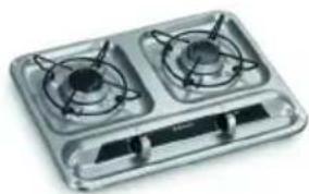
Exterior view of a two-gas stove appliance (no text or symbols visible)HB2325
natural_image
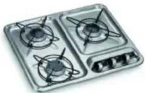
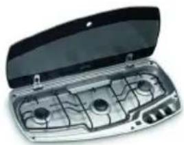
Illustration of a gas stove with three burners and a control panel (no text or symbols)HB3400
natural_image
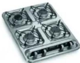
Four identical electric stove fans arranged in a square pattern on a metal tray (no text or symbols visible)HB4500
HBG2335
natural_image
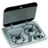
Open portable stove with internal compartments and control panel (no visible text or symbols)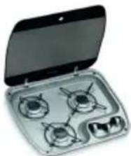
natural_image
Open gas stove kit with three burners and a handle (no visible text or labels)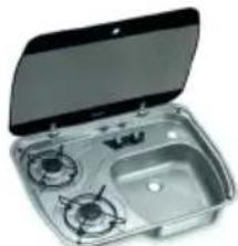
natural_image
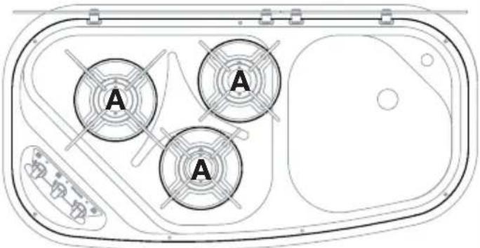
Open stainless steel kitchen appliance with two gas stovees and a side sink (no text or symbols visible)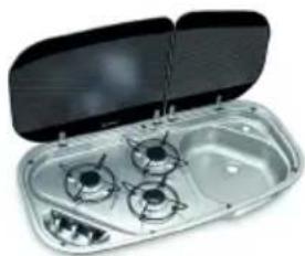
natural_image
Open storage dish containing three gas stove covers (no text or symbols visible)HBG3341 HBG3445 HSG2445 HSG3436
IT
Hobs and monobloc combinations
Installation, Use, and Maintenance ..... 29
FR
MOD. X mm Y mm
HB3400 470 370
HB4500 370 470
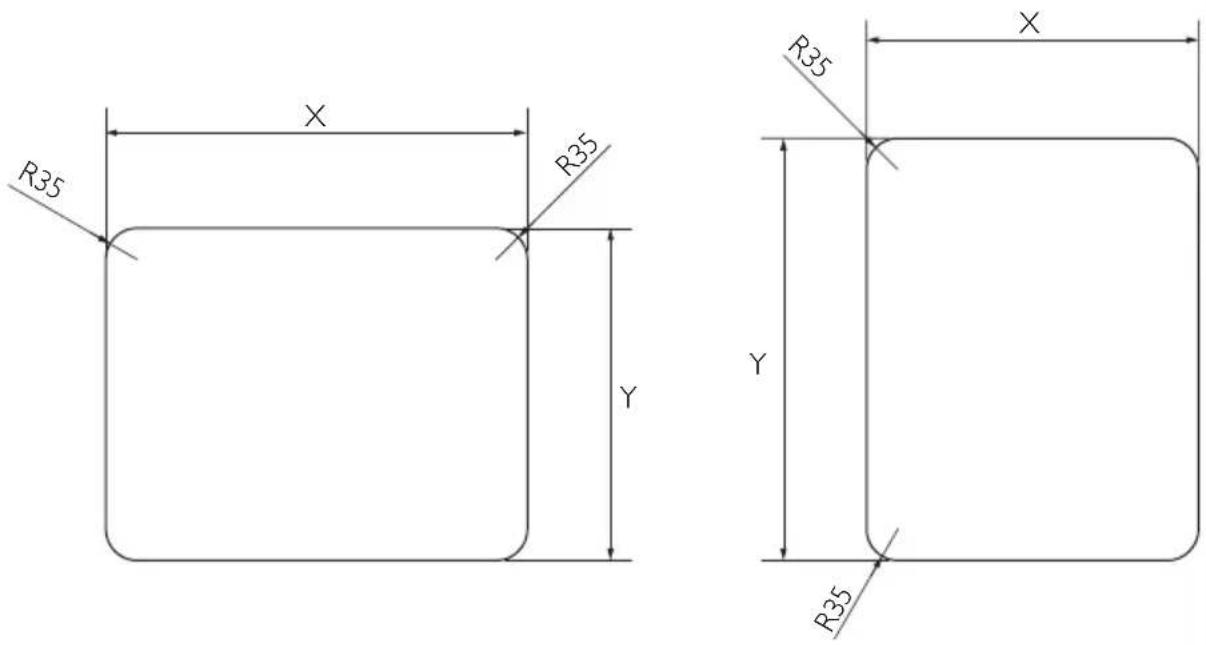
| MOD. | X mm | Y mm |
| HBG2335 | 440 | 315 |
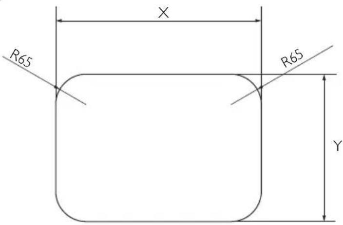
| MOD. | X mm | Y mm |
| HBG3341 | 678,4 | 333,6 |
| MOD. | X mm | Y mm |
| HBG3445 | 510 | 435 |
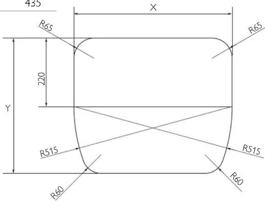
| MOD. | X mm | Y mm |
| HSG2445 | 590 | 435 |
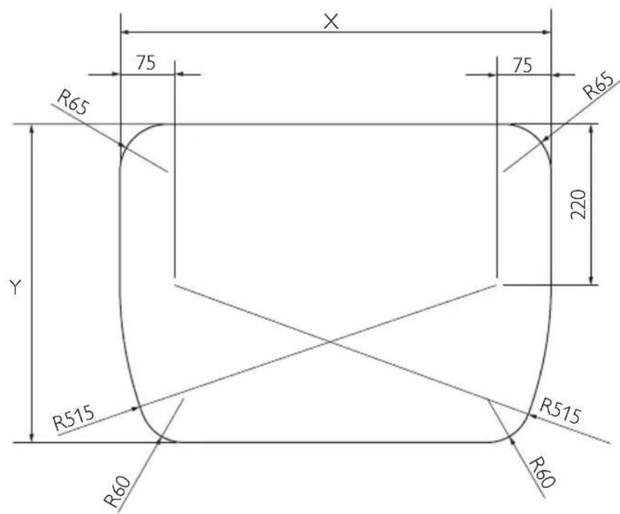
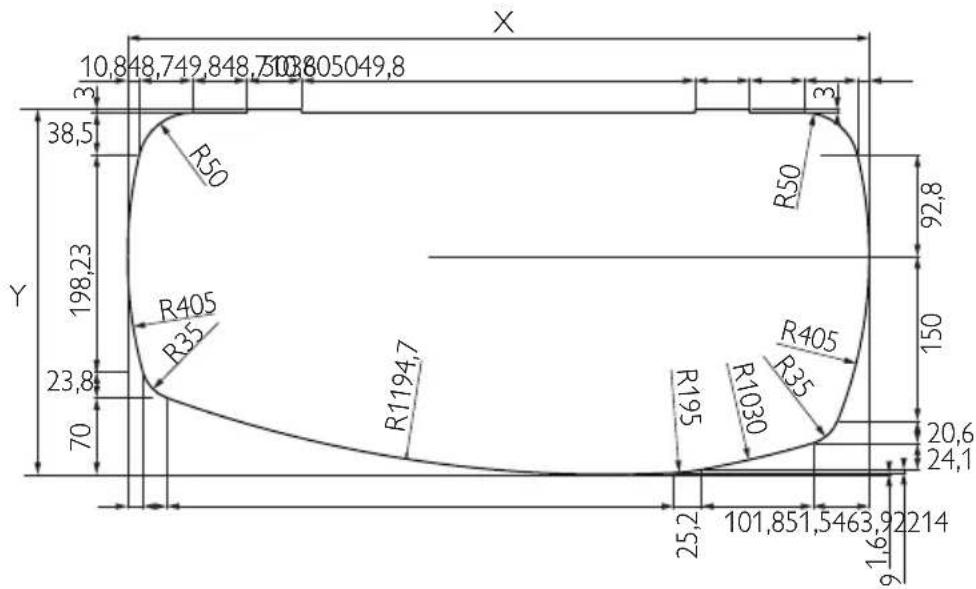
MOD. X mm Y mm
HSG3436 820 415,9
4
MOD:
HB2325
HB3400
HB4500
natural_image
Technical cross-sectional diagram of a mechanical assembly (no text or labels)MOD:
HBG2335
HBG3341
HBG3445
HSG2445
HSG3436
5
6
MOD: HB2325
natural_image
Technical diagram showing two circular components labeled 'A' with crosshair patterns, above a rectangular base with mounting holes (no text or symbols beyond the label)MOD: HB3400
MOD: HB4500
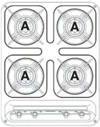
natural_image
Four circular panels labeled 'A' arranged in a 2x2 grid, with a small rectangular base below (no text or symbols on panels)MOD: HBG2335

MOD: HBG3341
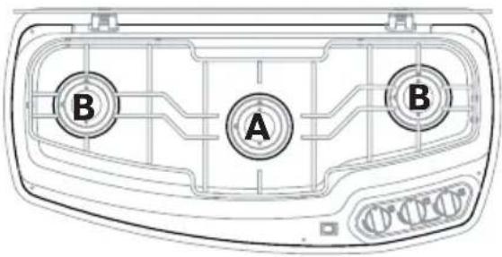
MOD: HBG3445
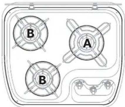
MOD: HSG2445
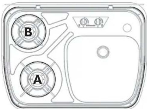
MOD: HSG3436
natural_image
Technical line drawing of a mechanical assembly with no visible text or symbolsBASSA TENSIONE 12 V=

ATTENZIONE!
natural_image
Two identical line drawings of a cooking pot with a horizontal double-headed arrow indicating pressure or force (no text or symbols)BRUCIATORE
Please read this instruction manual carefully before using the appliance. If the appliance is given to another party, the instruction manual must also be provided.
Table of contents
1 Explanation of symbols 30
2 General safety instructions....30
3 Contents of supply 31
4 Intended use....31
5 Installation....32
5.1 Installation hole....32
5.2 Gas connection....33
5.3 Electrical connections....35
5.4 Fixing 35
6 Technical description 36
6.1 Control panel 36
6.2 Burners....37
7 Use.... 38
7.1 Additional safety warnings .....38
7.2 Hob 39
7.3 Visual inspection of the flame 41
7.4 Gas cylinders....41
8 Cleaning and maintenance 43
8.1 Cleaning the appliance....43
8.2 Replacing injectors 43
9 Test pressure point (if fitted) 44
10 Warranty 44
1 Explanation of symbols

CAUTION!
Security warning: Ignoring this warning could cause serious injury or death.

IMPORTANT!
Failure to observe this note can cause material damages and affect the operation of the product.

NOTE
Additional information relative to the use of the product.
Action: this symbol indicates that action is required on your part. The required action is described step-by-step.
Fig. 1 5, page 3: this information refers to an element in a figure; in this case, the figure is found in "position 5 in figure 1 on page 3".
2 General safety instructions
The manufacturer does not assume any liability for damages in the following cases:
● damage to the product resulting from improper use
- changes to the product without express permission from the manufacturer
- use for purposes other than those described in the operating manual
• non-compliant installation and/or connections
- This warning is located on the appliance.
- This appliance must be installed according to the regulations in force and used only in a well ventilated area.
- Refer to the instructions before installing and using this appliance.
- The appliance must be installed by specialised technicians.
3 Contents of supply
| Reference | Quantity Name |
| Fig. 1, page 2 | |
| 11 Hob | |
| 21 Fixing screw bag (depending on model) | |
| 1 Instructions manual | |
4 Intended use
CAUTION!
This appliance can only be used to cook food. Any other use is deemed incorrect and therefore hazardous. The manufacturer declines liability for damage to property and injury to persons caused by improper, incorrect or irresponsible use.
5 Installation

CAUTION!
Before installation, check that the local distribution conditions (gas type and pressure) and the settings of the appliance compatible.
The adjustment conditions for this appliance are provided on the label (or on the data plate).
This appliance is not connected to a combustion product evacuation system. It must be installed and connected in accordance with the installation rules in force. Special attention must be given to relevant ventilation governing provisions.
5.1 Installation hole
CAUTION!
The appliance should be kept away from flammable materials.
This appliance belongs to CLASS 3: APPLIANCE TO BE BUILT INTO A KITCHEN UNIT OR WORKTOP.
Minimum distances to observe from the walls (Fig. 2, page 2)
Distance Position
135 mm From the outer edge of the burner head closest to one of the side walls and/or bottom.
500 mm Between the top of the burners and the furniture or shelves present above the hob.
30 mm The distance between the bottom of the burner and the underside.
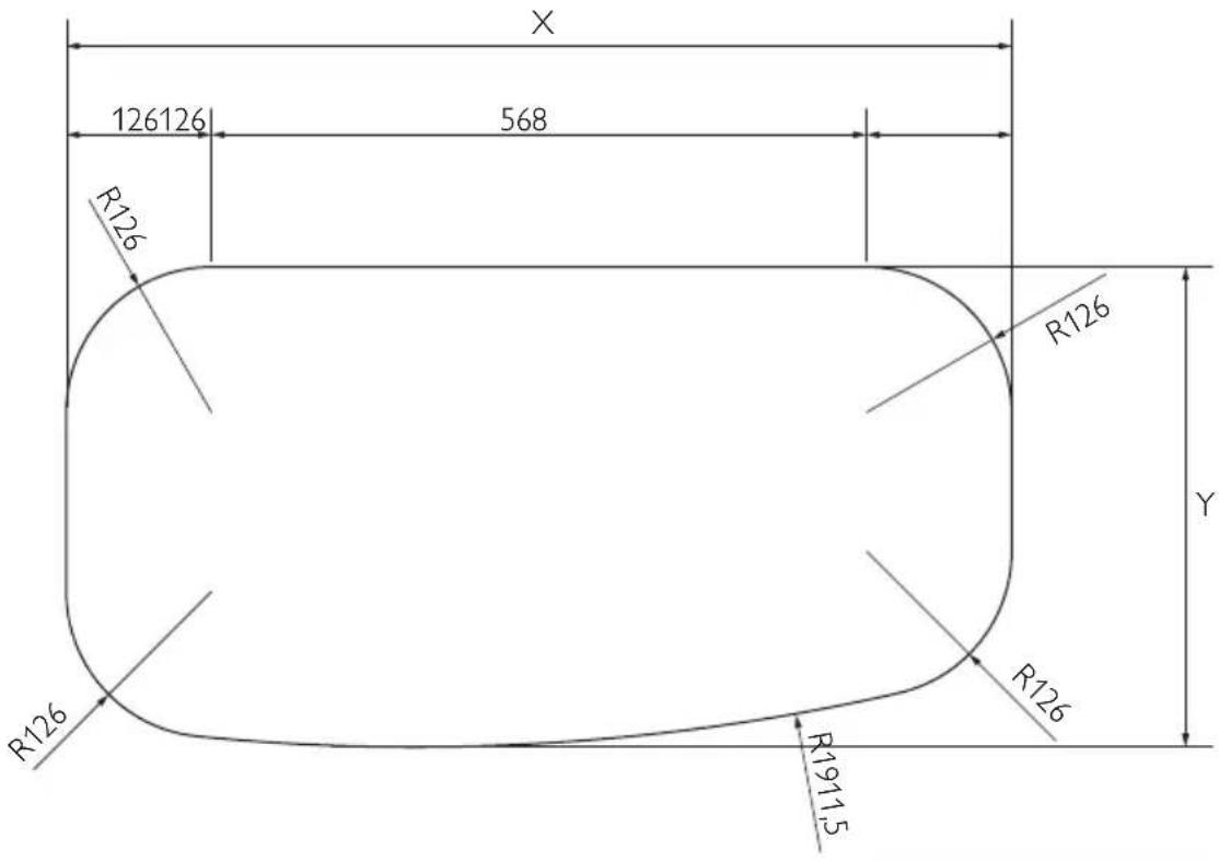
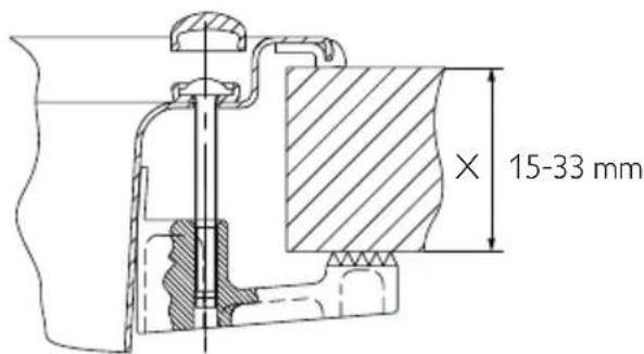
Built in hole dimensions
Depending on the model, make a hole in the cabinet as shown in Fig. 3, page 3.
The cabinet must be parallel to and flush with the horizontal worktop.
The cabinet built-in hole must be parallel. If the cabinet has aeration openings, prevent combustible materials from accessing these openings.
5.2 Gas connection

CAUTION!
Check this data before connecting the appliance to the gas cylinder. Pressure reducing valves to be used between the gas cylinder and the appliance must conform to the categories listed in the table below.
This appliance can be operated with the gases and related pressures described in the following table. The identification label glued to the appliance clearly shows the category (or categories) according to which the appliance has been adjusted.
| CATEGORY AND COUNTRIES OF DESTINATION | GAS PRESSURE | |
| I3B/P(30) | 30 mbar Butane (G30) | |
| AT BE DE DK FI GB NL NO PT SE SI | 30 mbar Propane (G31) | |
| I3+ (28-30/37) | 28-30 mbar Butane (G30) | |
| BE CH ES FR GB IE IT PT SI | 37 mbar Propane (G31) | |
| MODEL NOMINAL AND COMPLETEHEAT OUTPUT | VOLUME OF AIRREQUIRED FORCOMBUSTION | |
| kW - gr/h | m3/h | |
| HB2325 | 3.2 - 233 6.4 | |
| HB3400 | 4.8 - 350 9.6 | |
| HB4500 | 6.4 - 466 12.8 | |
| HBG2335 | 2.6 - 190 5.2 | |
| HBG3341 | 3.6 - 262 7.2 | |
| HBG3445 | 3.6 - 262 7.2 | |
| HSG2445 | 2.6 - 190 5.2 | |
| HSG3436 | 4.8 - 350 9.6 | |

CAUTION!
During installation and connection, the gas conductor of the appliance must not be subject to twisting, pulling or other stresses.
The gas pipeline connection to the appliance must be done using a rigid metal pipe and sealing connections.
It is possible to use a hose, but it must:
- Allow for inspection at all times.
- Be protected from possible contact with heatable parts (such as the underside of the burners).
- Be protected from any stress (torsion, tensile, compression, etc.).
- Be protected from the moving parts of the cabinet (e.g. a drawer).
- Have a maximum length of 1.5 m.
- Be replaced before its expiration date.
Once connected, check the gas circuit seal by using a non-corrosive fluid to detect any leaks. Do not use a soap and water solution. DO NOT USE AN OPEN FLAME.
5.3 Electrical connections
LOW VOLTAGE 12 V=

CAUTION!
This appliance must be connected to a 12 V power pack. If a 2 x 0,5 mm ^2 cable is used for the connection, its length must not exceed 2 meters. When wiring the appliance respect correct polarity!

CAUTION!
Never connect the appliance to the main voltage (230 V\~); this would result in the ultimate destruction of the parts and a hazard to the user.
To connect the appliance, use a double cable and connect it to the terminal board identified with “+12 V—”, found on the back side of the appliance. The red terminal is the positive pole, while the black terminal is the negative pole.
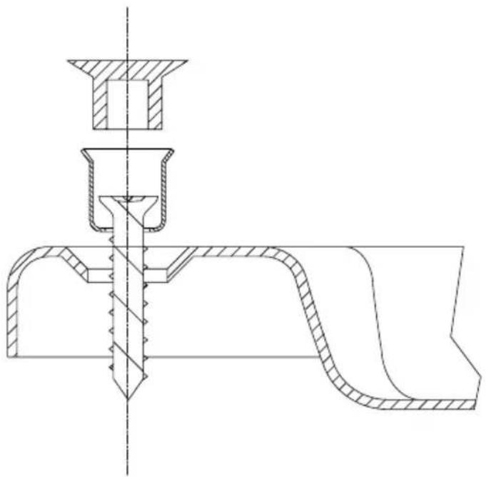
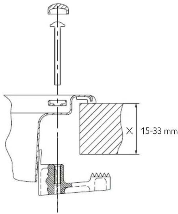
5.4 Fixing
Depending on the model, the appliance must be fixed to the cabinet using the screws as described in Fig. 4, page 7.
6 Technical description
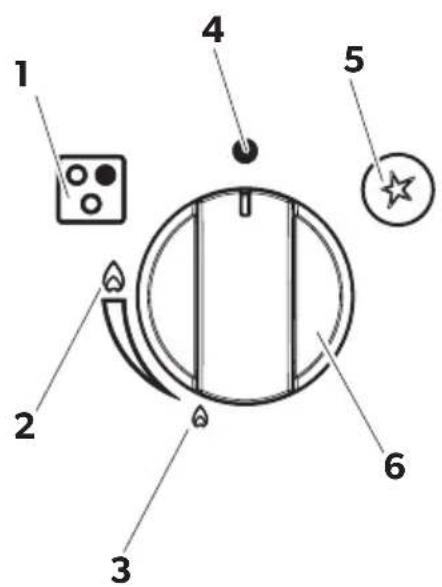
6.1 Control panel
The following table shows all the buttons and symbols on the appliance.

NOTE
Buttons and symbols may vary depending on the model.
Reference
Symbol Description
Fig. 5, page 8
1 Indicates the control knob of a knob
burner.
5 Button to actuate electronic ignition.

2 Maximum adjustment of the flame.

4 Gas turned off.

3 Minimum adjustment of the flame.
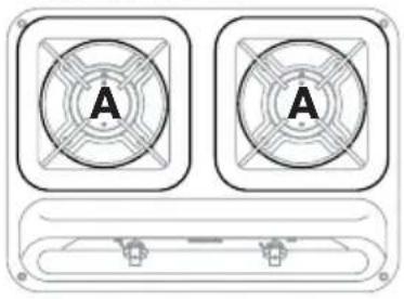
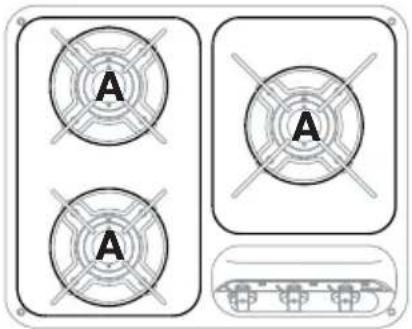
6.2 Burners
| MODELReferenceFig. 6, page 9 | A∅ 64 mm | B∅ 50 mm | ||||
| No. kW | gr/h No. | kW gr/h | ||||
| HB2325 | 21.6 | 116.8 | ||||
| HB3400 | 31.6 | 116.8 | ||||
| HB4500 | 41.6 | 116.8 | ||||
| HBG2335 | 11.6 | 116.8 11 | 73 | |||
| HBG3341 | 11.6 | 116.8 21 | 73 | |||
| HBG3445 | 11.6 | 116.8 21 | 73 | |||
| HSG2445 | 11.6 | 116.8 11 | 73 | |||
| HSG3436 | 31.6 | 116.8 | ||||
7 Use
7.1 Additional safety warnings
CAUTION!
This appliance must only be used by responsible adults. The accessible parts may be hot during and immediately after use; do not touch them and keep children away. After cooking, return the knob(s) to the closed position(s). After use, close the main gas line tap.
CAUTION!
The use of a gas cooking appliance leads to the generation of heat and moisture in the room in which it is installed. Make sure to provide good ventilation in the kitchen: keep natural ventilation openings open or install a mechanical ventilation device (mechanical extractor hood).
Intense and prolonged use of the appliance may require supplementary aeration such as the opening of a window or more effective ventilation such as an increase in the power of the possible mechanical extractor hood.
This warning is clearly shown on the glass cover of the hob. The glass covers may break if heated. Ignition of any of the burners (hob, oven and grill) must always be done with the cover raised, and always turn off all the burners (hob, oven and grill) and leave them to cool down before closing the cover.
CAUTION!
This warning refers to models with incorporated sink unit and hob and with glass lid divided between sink and hob. This warning is affixed in a visible position on the sink unit glass lid. When using the hob with the glass lid on the sink unit closed, always keep pans on hob at a distance of 10 mm minimum from sink unit glass lid.
7.2 Hob
Selecting the burner
CAUTION!
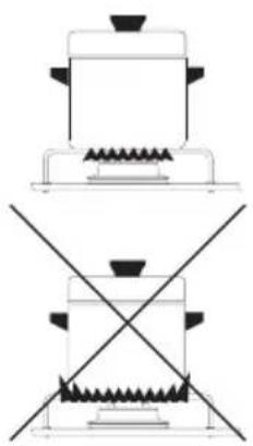
The flame must not spread over the edges of the cookware. Place the cookware centrally on the burner, so that it is stable on the support grid.
natural_image
Diagram showing two identical heating setups with a stove and a cross-shaped heating element (no text or symbols)BURNER Reference Fig. 6, page 9
A ∅ 64 mm
COOKWARE DIAMETER
B ∅ 50 mm
from 160 mm to 220 mm
Electronic ignition of the hob

CAUTION!
Ignition must be done without any cookware or other object on the burners.
To generate the flame, fully press down the control knob (Fig. 5 6, page 8) and turn it to the large flame position (Fig. 5 2, page 8).
▶ Simultaneously push down the electronic ignition button (Fig. 5 5, page 8).
Once the flame has been generated, press the knob down for a few seconds so that the flame remains lit.

CAUTION!
If the burner does not turn on:
- turn the knob to the small flame position (Fig. 5 3, page 8);
• proceed with manual ignition; - check that there is gas in the cylinder.
If the device does not work, close the gas inlet tap and contact your dealer.
Manual ignition of the hob
If the electronic ignition does not work, the manual ignition is used as a substitute.

CAUTION!
Ignition must be done without any cookware or other object on the burners.
To generate the flame, fully press down the control knob (Fig. 5 6, page 8) and turn it to the large flame position (Fig. 5 2, page 8).
▶ Simultaneously ignite the burner with a match or gas lighter.
Once the flame has been generated, press the knob down for a few seconds so that the flame remains lit.

CAUTION!
If the burner does not turn on:
- check that there is gas in the cylinder.
If the device does not work, close the gas inlet tap and contact your dealer.
Regulating the hob flame
To adjust the flame, turn the knob to the desired position (Fig. 5 6, page 8).
7.3 Visual inspection of the flame
Depending on the type of gas used, the flame appears as follows:
- Propane (G31): flame with blue internal pin point and clear outline.
- Butane (G30): flame with slight yellow tips when igniting the burner; these tips intensify as the burner heats.
7.4 Gas cylinders

CAUTION!
The use of gas and/or a pressure different from those indicated by the manufacturer could cause irregular and incorrect operation of the appliance. The manufacturer declines all liability for the incorrect or improper use of the appliance.
The gas cylinders to be used are the most common in the country where the appliance is used. The gas to be used is clearly indicated on the outside of the packaging and on the indelible label attached on the back of the appliance. In any case, observe the following: Gas cylinders with valve and pressure reducer must be placed in an upright position and in the appropriate compartment, and access should not be impeded. Replacement of the cylinders must be performed without impediment and with ease.
Replacing the gas cylinder
▶ Close the taps of the appliance.
▶ Make sure no flames or fire are nearby.
▶ Close the valve of the cylinder to be replaced.
Unscrew the pressure reducer of the empty cylinder, take it out of the compartment.
▶ Proceed in reverse order for replacement.
▶ Check for gas leaks with the use of a non-corrosive fluid.

CAUTION!
- Do not use a soap and water solution.
- Do not use an open flame.
▶ Turn on the burners and check for proper operation, otherwise contact an authorised technician.
CLOSE THE CYLINDER GAS SUPPLY AFTER USE.
GAS LEAKS
We recommend using a certified electronic gas leak detector.
If you smell gas:
Open the windows and immediately get all people out of the camper, caravan etc.
▶ Never touch electrical switches, light matches or do anything that could ignite the gas.
Extinguish any open flame.
- Close the cylinder valve or gas tank, and do not open the valve until the gas leak has been detected and eliminated.
▶ Contact an authorised technician.
8 Cleaning and maintenance
8.1 Cleaning the appliance

CAUTION!
Before cleaning, switch off the appliance, disconnect it from the mains power supply and wait for it to cool down.

IMPORTANT!
Hot surfaces could be damaged if they come into contact with cold water or a damp cloth.
Do not use abrasive, corrosive, chlorine-based products, scourers or steel wool.
Do not leave acid or alkaline substances (vinegar, salt, lemon juice, etc.) on appliance surfaces.
For stainless steel surfaces and enamelled parts: wash with soap and water or mild detergent, rinse and dry. Use clean sponges and cloths.
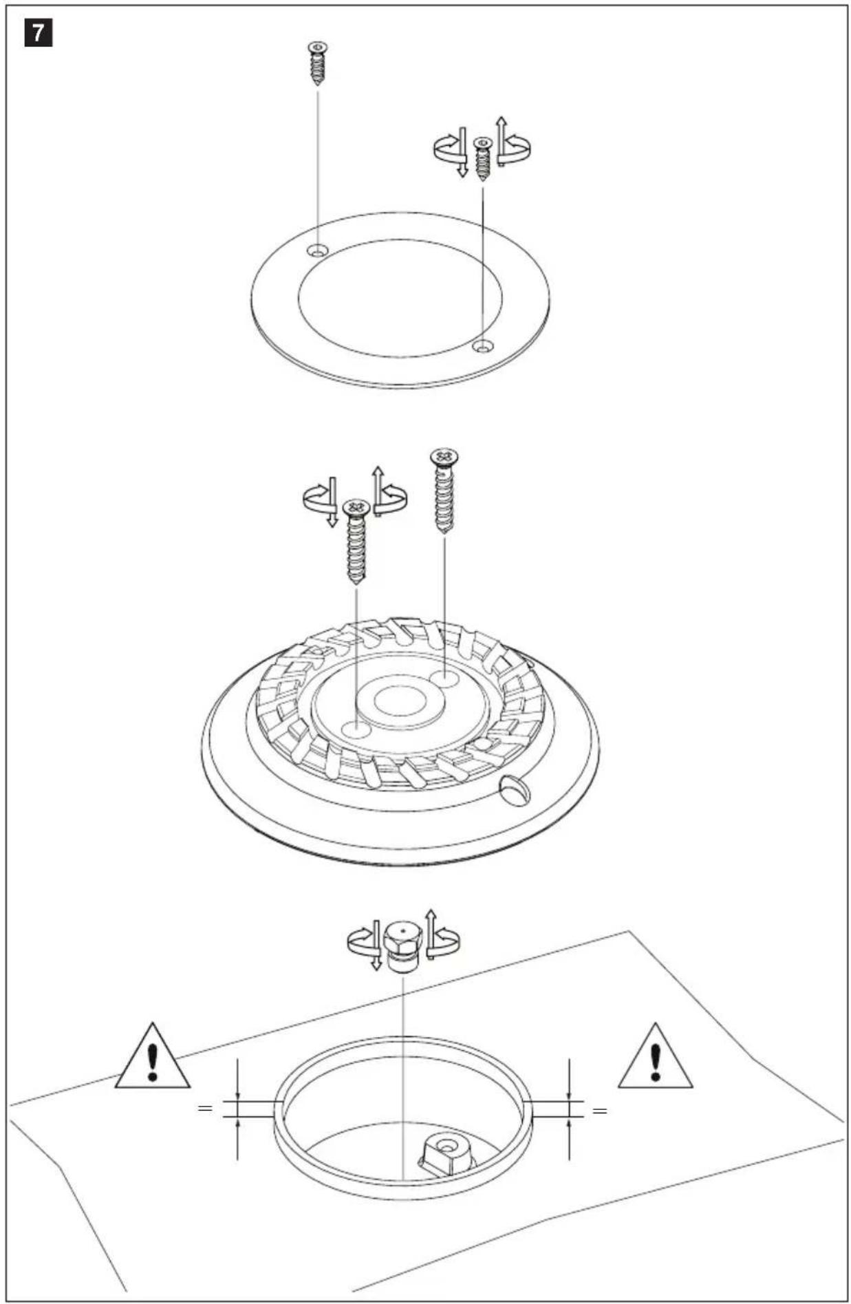
8.2 Replacing injectors
CAUTION!
The activities must be done by authorised personnel. After this operation, we decline all liability resulting from the intervention.
▶ Reference Fig. 7, page 10.
| BURNER | ||
| ReferenceFig. 6, page 9 | ∅ INJECTOR (mm) | NUMBER PRINTED ONINJECTOR |
| A∅ 64 mm | 0.64 64 | |
| B∅ 50 mm | 0.50 50 | |
9 Test pressure point (if fitted)
The test pressure point (pressure check valve) is fitted under the hob (Fig. 8, page 11).
Removing and mounting this test pressure point (pressure check valve) must be performed by a qualified gas service engineer. Gas pressure is related to the type of gas used to supply the appliance. Refer to chapter GAS in this manual.
10 Warranty
The statutory warranty period applies. If the product is defective, please contact the local manufacturer in your country (the address is on the back of the instruction manual) or your reference specialised dealer.
For repair and warranty processing, the following documents must be included when sending the appliance:
- a copy of the receipt showing the date of purchase;
- a reason for the claim or a description of the fault.
BASSE TENSION 12 V =
ATTENTION!
6 Description technique
natural_image
Two diagrams showing a cooking pot and a heating device with crossed lines indicating resistance (no text or symbols)BRÛLEUR
Repère
Fig. 6, page 9
DIAMÈTRE CASSEROLES
A ∅ 64 mm
de 160 mm à 220 mm
B ∅ 50 mm
de 90 mm à 150 mm
natural_image
Diagram showing two identical electrical circuit symbols: a top panel with a pot and heating element, and a bottom panel with a switch and heating element (no text or labels)natural_image
Diagram showing two identical heating setups with a stove and a heater, crossed by diagonal lines (no text or symbols)QUEMADOR
natural_image
Diagram showing two identical electrical circuit symbols: a top panel with a pot and heating element, and a bottom panel with a switch and heating element (no text or labels)QUEIMADOR
natural_image
Diagram showing two identical heating setups with a stove and a heater, crossed by diagonal lines (no text or symbols)BRÆNDER
Reference Fig. 6, side 9
A ∅ 64 mm
GRYDEDIAMETER
natural_image
Diagram showing two identical heating setups with a stove and a cross-shaped heating element (no text or labels)POLTIN
natural_image
Two schematic diagrams of a cooking appliance with no text or symbolsBRÄNNARE
Referens Bild 6, sid. 9
A ∅ 64 mm
natural_image
Two schematic diagrams of a cooking appliance with no text or symbolsBRENNER
Referanse Fig. 6, side 9
A ∅ 64 mm
GRYTENES DIAMETER
160-220 mm
B ∅ 50 mm
90-150 mm
Elektronisk tenning av platetoppen

ADVARSEL!
RAZRED IN DRŽAVE, KJER JE V UPORABI PLINSKI TLAK
| I3B/P(30) | 30 mbar Butan (G30) | |
| AT BE DE DK FI GB NL NO PT SE SI | 30 mbar Propan (G31) | |
| I3+ (28-30/37) | 28-30 mbar Butan (G30) | |
| BE CH ES FR GB IE IT PT SI | 37 mbar Propan (G31) | |
| MODEL SKUPNA NOMINALNA TOPLOTNA MOČ | POTREBNA KOLIČINA ZRAKA ZA ZGOREVANJE m^3/h | |
| kW - g/h | ||
| HB2325 | 3,2 - 233 6,4 | |
| HB3400 | 4,8 - 350 9,6 | |
| HB4500 | 6,4 - 466 12,8 | |
| HBG2335 | 2,6 - 190 5,2 | |
| HBG3341 | 3,6 - 262 7,2 | |
| HBG3445 | 3,6 - 262 7,2 | |
| HSG2445 | 2,6 - 190 5,2 | |
| HSG3436 | 4,8 - 350 9,6 | |

POZOR!
natural_image
Diagram showing two identical heating setups with a stove and a heater, crossed by diagonal lines (no text or symbols)GORILNIK
Sklic na Sliko 6, stran 9
A ∅ 64 mm
PREMER POSODE
od 160 mm do 220 mm
B ∅ 50 mm
od 90 mm do 150 mm
Dometic Australia Pty. Ltd.
1 John Duncan Court
Varsity Lakes QLD 4227
1800212121
+61755076001
Mail: sales@dometic-waeco.com.au
AUSTRIA
Dometic Austria GmbH
Neudorferstraße 108
A-2353 Guntramsdorf
+43 2236 908070
+43 2236 90807060
Mail: info@dometic.at
BENELUX
Dometic Branch Office Belgium
Zincstraat 3
B-1500 Halle
+32 2 3598040
+32 2 3598050
Mail: info@dometic.be
BRAZIL
Dometic DO Brasil LTDA
Avenida Paulista 1754, conj. 111
SP 01310-920 Sao Paulo
+55 11 3251 3352
+551132513362
Dometic Group Asia Pacific
Suites 2207-11 · 22/F · Tower 1
The Gateway · 25 Canton Road,
Tsim Sha Tsui · Kowloon
+852 2 4611386
+852 24665553
Mail: info@waeco.com.hk
HUNGARY
Dometic Zrt. Sales Office
Kerékgyártó u. 5.
H-1147 Budapest
+3614684400
+3614684401
Domettic Italy S.r.l.
Via Virgilio, 3
I-47122 Forli (FC)
+39 0543 754901
+39 0543 754983
Mail: vendite@dometic.it
IAPAN
Dometic KK
Maekawa-Shibaura, Bldg. 2
2-13-9 Shibaura Minato-ku
Tokyo 108-0023
+81354453333
+81354453339
Mail: info@dometic.jp
MEXICO
Circuito Médicos No. 6 Local 1
Colonia Ciudad Satélite
CP 53100 Naucalpan de Juárez
Estado de México
+52 55 5374 4108
+52 55 5393 4683
Mail: info@dometic.com.mx
NETHERLANDS
Dometic Benelux B.V.
Ecustraat 3
NL-4879 NP Elten-Leur
+31765029000
+31765029019
Mail: info@dometic.nl
NEW ZEALAND
Dometic New Zealand Ltd.
Unite E, The Gate
373 Neilson Street
Penrose 1, Auckland
+6496221490
+6496221573
Mail: customerservices@dometic.co.nz
NORWAY
Dometic Norway AS
∅sterøyveien 46
N-3232 Sandefjoro
+4733428450
+4733428459
Mail: firmapost@dometic.no
POLAND
Dometic Poland Sp. z o.o.
Ul. Puławska 435A
PL-02-801 Warszawa
+48 22 414 3200
+48 22 414 3201
Mail: info@dometic.pl
PORTUGAL
Dometic Spain, S.L.
Komsomolskaya square 6-1
RU-107140 Moscow
+7 495 780 79 39
+7 495 916 56 53
Mail: info@dometic.ru
SINGAPORE
Dometic Pte Ltd
18 Boon Lay Way 06-140 Trade Hub 21
Singapore 609966
+65 6795 3177
+65 6862 6620
Mail: dometic@dometic.com.sg
SLOVAKIA
Dometic Slovakia s.r.o. Sales Office Bratislava
Nádražná 34/A
900 28 Ivánka pri Dunaji
+421 2 45 529 680
Mail: bratislava@dometic.com
SOUTH AFRICA
Dometic (Pty) Ltd.
Regional Office
South Africa & Sub-Saharan Africa
2 Avalon Road
West Lake View Ext 11
Modderfontein 1645
Johannesburg
+27114504978
+27114504976
Mail: info@dometic.co.za
SPAIN
Dometic Spain S.L.
Avda, Sierra del Guadarrama, 16
E-28691 Villanueva de la Cañada
Madrid
+34902111042
+34 900 100 245
Mail: info@dometic.es
SWEDEN
Dometic Scandinavia AB
Gustaf Melins gata 7
Dometic Switzerland AG
Riedackerstrasse 7a
CH-8153 Rümlang
+41448187171
+41 44 8187191
Mail: info@dometic.ch
UNITED ARAB EMIRATES
Dometic Middle East FZCO
P.O.Box 17860
S-D 6, lebel Ali Freezone
Dubai
+97148833858
+97148833868
Mail: info@domelic.ae
UNITED KINGDOM
Dometic UK Ltd.
Dometic House, The Brewery
Blandford St. Mary
Dorset DT119LS
+44 344 626 0133
+443446260143
Mail: customerservices@dometic.co.uk
USA
Dometic RV Division
1120 North Main Street
Elkhart, IN 46515
+1574-264-2131


- HOBS AND COMBINATIONS
- Hobs and monobloc combinations
- X mm Y mm
- 4
- MOD:
- BASSA TENSIONE 12 V=
- ATTENZIONE!
- BRUCIATORE
- Table of contents
- Explanation of symbols
- CAUTION!
- IMPORTANT!
- NOTE
- General safety instructions
- Contents of supply
- Intended use
- Installation
- Installation hole
- Minimum distances to observe from the walls (Fig. 2, page 2)
- Distance Position
- Built in hole dimensions
- Gas connection
- Electrical connections
- LOW VOLTAGE 12 V=
- Fixing
- Technical description
- Control panel
- Reference
- Symbol Description
- Fig. 5, page 8
- Burners
- Use
- Additional safety warnings
- Hob
- Selecting the burner
- Electronic ignition of the hob
- Manual ignition of the hob
- Regulating the hob flame
- Visual inspection of the flame
- Gas cylinders
- Replacing the gas cylinder
- CLOSE THE CYLINDER GAS SUPPLY AFTER USE.
- GAS LEAKS
- If you smell gas:
- Cleaning and maintenance
- Cleaning the appliance
- Replacing injectors
- Test pressure point (if fitted)
- Warranty
- BASSE TENSION 12 V =
- ATTENTION!
- Description technique
- BRÛLEUR
- Repère
- Fig. 6, page 9
- DIAMÈTRE CASSEROLES
- QUEMADOR
- QUEIMADOR
- BRÆNDER
- GRYDEDIAMETER
- POLTIN
- BRÄNNARE
- BRENNER
- GRYTENES DIAMETER
- Elektronisk tenning av platetoppen
- ADVARSEL!
- POZOR!
- GORILNIK
- PREMER POSODE
- Dometic Australia Pty. Ltd.
- AUSTRIA
- Dometic Austria GmbH
- BENELUX
- Dometic Branch Office Belgium
- BRAZIL
- Dometic DO Brasil LTDA
- Dometic Group Asia Pacific
- HUNGARY
- Dometic Zrt. Sales Office
- Domettic Italy S.r.l.
- IAPAN
- Dometic KK
- MEXICO
- NETHERLANDS
- Dometic Benelux B.V.
- NEW ZEALAND
- Dometic New Zealand Ltd.
- NORWAY
- Dometic Norway AS
- POLAND
- Dometic Poland Sp. z o.o.
- PORTUGAL
- Dometic Spain, S.L.
- SINGAPORE
- Dometic Pte Ltd
- SLOVAKIA
- Dometic Slovakia s.r.o. Sales Office Bratislava
- SOUTH AFRICA
- Dometic (Pty) Ltd.
- Regional Office
- South Africa & Sub-Saharan Africa
- SPAIN
- Dometic Spain S.L.
- SWEDEN
- Dometic Scandinavia AB
- Dometic Switzerland AG
- UNITED ARAB EMIRATES
- Dometic Middle East FZCO
- UNITED KINGDOM
- Dometic UK Ltd.
- USA
- Dometic RV Division
Brand : DOMETIC
Model : HSG 3436
Category : Cooker