Motor Chroma Key Green Screen - Projection screen Celexon - Free user manual and instructions
Find the device manual for free Motor Chroma Key Green Screen Celexon in PDF.


User questions about Motor Chroma Key Green Screen Celexon
0 question about this device. Answer the ones you know or ask your own.
Ask a new question about this device
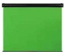
Download the instructions for your Projection screen in PDF format for free! Find your manual Motor Chroma Key Green Screen - Celexon and take your electronic device back in hand. On this page are published all the documents necessary for the use of your device. Motor Chroma Key Green Screen by Celexon.
USER MANUAL Motor Chroma Key Green Screen Celexon
natural_image
Solid green rectangular panel with black horizontal band at top (no text or symbols)natural_image
Solid green square with black top border (no text or symbols)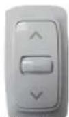
natural_image
Isometric line drawing of a metal bracket with mounting holes (no text or symbols)natural_image
Simple L-shaped line drawing with no text, numbers, or symbolsnatural_image
Diagram of a device with three cables and connectors, no text or symbols present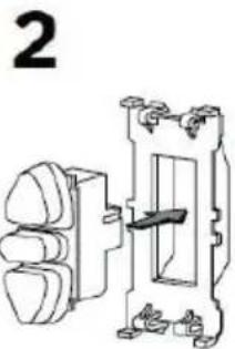
natural_image
Technical line drawing of a mechanical switch or fuse assembly (no text or symbols)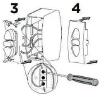
text_image
Technical diagram showing exploded view of electrical switchgear assembly with numbered parts and component labelsWANDMONTAGE (GESCHRAUBT)
text_image
L L/8 L/8natural_image
Technical line drawing of a mechanical bracket with multiple screw fasteners (no text or symbols)DECKENMONTAGE (GESCHRAUBT)
text_image
L L/8 L/8natural_image
Simple line drawing of a mechanical component with mounting holes (no text or symbols)AUFHÄNGUNG
Operating instructions
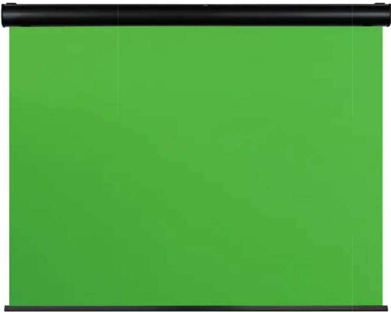
celexon Electric Chroma Key Green Screen
natural_image
Solid green rectangular panel with black horizontal band at top (no text or symbols)Thank you for purchasing this product.
For optimum performance and safety, please read these instructions carefully before connecting or operating this product. Please retain these instructions for future reference.
WARNINGS
These operating instructions are intended to familiarise you with the operation of this product. Keep this manual in a safe place so that you can refer to it at any time.
- Before installation, please refer to the data sheet for further safety and use instructions.
- Do not start installation until you have read and understood the complete operating instructions.
- Carry out the installation with another person to ensure safe installation.
- Remove the product from its packaging and remove all packaging materials. Make sure that there is no packaging material on or in the product. If you notice any damage to the packaging, also check for damage to the product. If you notice any external damage to the unit or unexpected unusual functioning, do not continue to use the product. Immediately contact the dealer from whom you purchased the product or celexon directly (Web: www.celexon.co.uk, Mail: info@celexon.co.uk) for further information.
- To ensure trouble-free operation, the product must only be used indoors, it is NOT suitable for outdoor use.
- Children under the age of 16 are not permitted to use the unit or its accessories.
- Ensure that no children play with the equipment or are in the vicinity without supervision.
- Conversion or modification of the product impairs product safety and is not permitted.
- Caution: Risk of injury! Never open the product without authorisation. Never carry out repairs yourself!
- This product may only be used in its original manufacturer's condition and with any original accessories.
- Do not use the product in the vicinity of gas or water-conveying equipment or in a dusty environment.
- Handle the product with care. It may be damaged by knocks, blows or falling from even a small height.
- Keep the product away from moisture and heat.
- Never immerse the product in water or other liquids.
- Only use the product in its intended manner. Any other use may result in damage to the product or its surroundings.
- Tighten the screws, but do not overtighten them. Tightening too tight (e.g. by using a cordless screwdriver) can cause damage and affect the secure hold of the screen.
- Suspended loads must be checked for strength and load-bearing capacity at least twice a year.
- Caution: Risk of injury! The unit closes flush and firmly when retracted. Keep fingers, hands or other small parts away from the opening.
- All supply lines and cables must not be subjected to additional loads and must be laid in such a way that they are not damaged or crushed.
- Failure to follow the above instructions may result in personal injury and damage to the product or equipment connected to it. Incorrect installation or use may also invalidate the warranty.
- If you are unsure about the use of the product, please contact your specialist personnel, your dealer or celexon directly (Web: www.celexon.co.uk, Mail: info@celexon.co.uk).
- Technical changes and errors excepted.
The manufacturer accepts no responsibility for damage to property or personal injury if the screen is used outside the recommended specifications, or in cases of improper installation. Do not use this screen near heaters or air conditioners. Also, do not mount the product in direct sunlight or in front of a window. Due to the temperature-sensitive PVC surface, the projection screen fabric may be permanently damaged.
We recommend that you wait approx. 2 hours after delivery before installing the projection screen. This way the screen can acclimatise, especially if the screen is moved from a cold to a warm environment.
Please avoid any stains on the surface of the screen. These may not be able to be removed.
The positions of the end points are already optimally set at the factory and should not be changed. Especially with motorised screens, the entire length of the screen should always be used in order to achieve the best flatness. An adjustment of a few cm of the end switch-off points should only be made by persons with specialist knowledge and in consultation with the manufacturer. Incorrect adjustment can result in damage to the projection surface.
DISCLAIMER
The information in this document is subject to change without notice by the manufacturer. Changes will be added to subsequent versions of this manual. Errors excepted.
CARE INSTRUCTIONS
NEVER clean the screen with alcohol or other cleaning agents containing solvents. Use only a soft and clean cloth. If necessary, dirt can be removed from the surface with a mild soap solution (max. 5%). It is essential to avoid contact with pointed or sharp objects. These could permanently damage the projection screen fabric. For further instructions, please refer to the enclosed projection screen instructions.
TECHNICAL DATA
Voltage: 220 V \~ 240 V, 50 Hz
Consumption: 130 W (MAX)
0,4 W (standby)
text_image
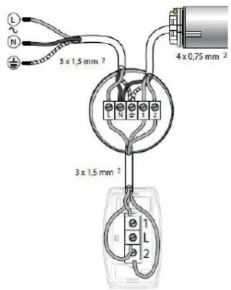
3 x 1,5 mm 2 4 x 0,75 mm 2 3 x 1,5 mm 2| Terminal Mains Drive (EUR) Drive (US$) | |||
| L Phase (L) | |||
| N Zero point (N) Blue White | |||
| Earth (⊕) | Yellow Green Green | ||
| 1 Brown or Black Red or Black | |||
| 2 | Brown or Black Red or Brown | ||
IN THE BOX
natural_image
Solid green rectangular panel with black top border (no text or symbols)natural_image
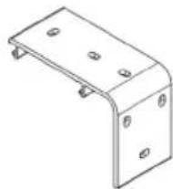
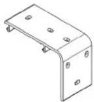
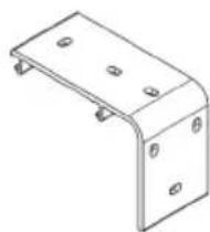
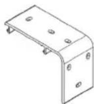
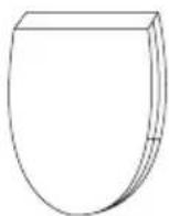
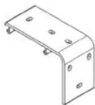
Isometric line drawing of a metal bracket with mounting holes (no text or symbols)2x Side cap 2x Mounting bracket
natural_image
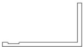
Simple L-shaped line drawing with no text, numbers, or symbols2x Plastic safety catch
INSTALLATION NOTE
Before installation, please check that all the parts listed above are included. If any parts are missing, contact the dealer from whom you purchased the product and wait until all parts are present before attempting installation. The screen can be installed on the wall or ceiling. Procure suitable mounting material for your installation surface.
ELECTRICAL INSTALLATION
-
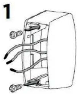
Mount the switch housing by leading the current-carrying cables through the housing to the outside and fix the switch to the surface with the enclosed screws.
-
Insert the buttons into the frame.
-
Wire the back of the push-button according to the above wiring diagram.
- Carefully insert the buttons into the switch housing and close it with the switch cover.
natural_image
Diagram of a mechanical or electrical component with multiple wires and connectors (no text or symbols)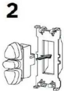
natural_image
Technical line drawing of a mechanical switch or electrical component with no visible text or symbols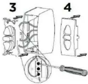
text_image
Technical diagram showing installation of a wall-mounted electrical switch with labeled parts 3 and 4WALL MOUNTING (SCREWED)
text_image
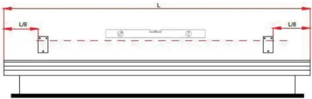
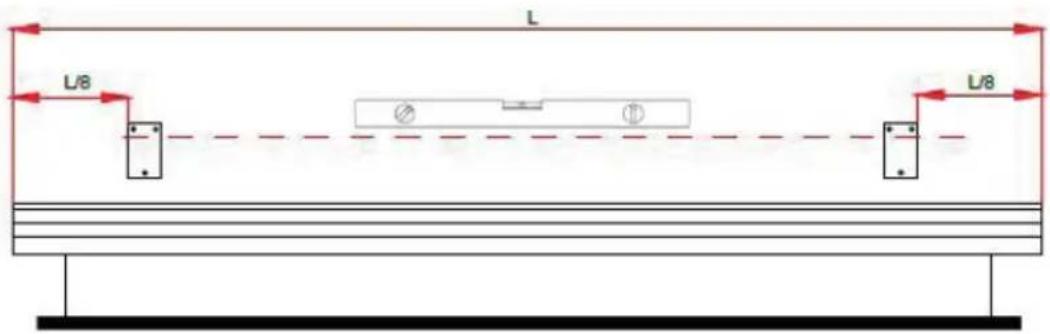
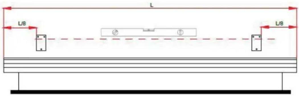
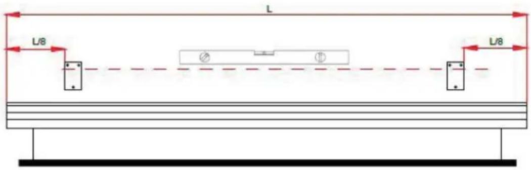
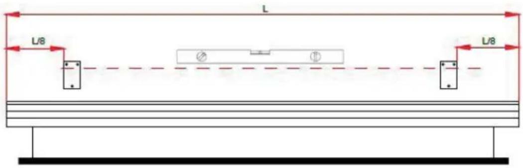
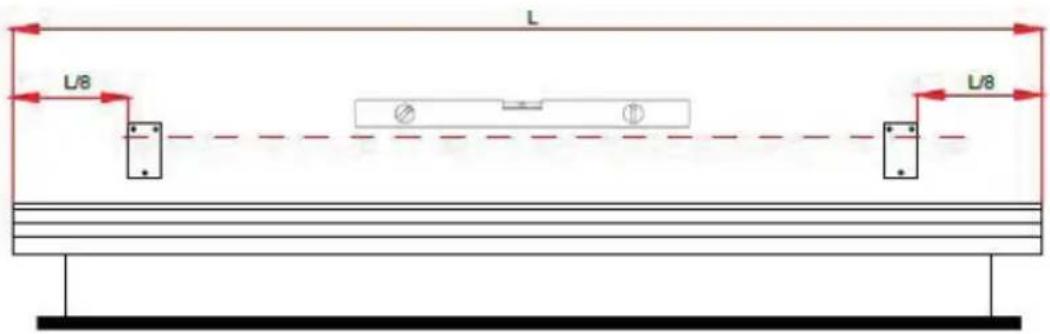
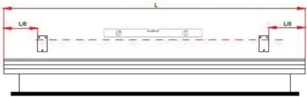
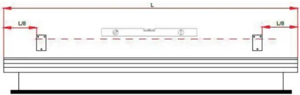
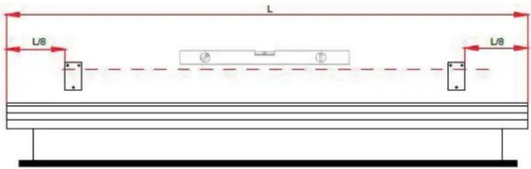
L L/8 L/8Measure the length of the casing and divide this value by 8 and place the mounting brackets according to the drawing above.
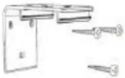
Draw a line to bring the two mounting brackets in alignment. Use the mounting brackets as a guide and mark the holes on the wall with a pencil. Then drill holes according to the marked holes with a drill and insert suitable dowels into the holes (the dowels must be firmly seated in the holes). Fasten the mounting brackets to the wall with suitable screws.

text_image
148 123 152 86 29
natural_image
Technical line drawing of a mechanical bracket with multiple screw fasteners (no text or symbols)CEILING MOUNTING (SCREWED)
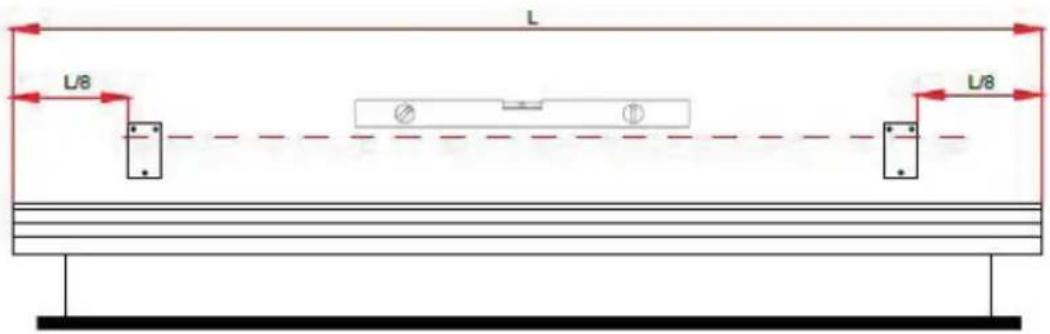
text_image
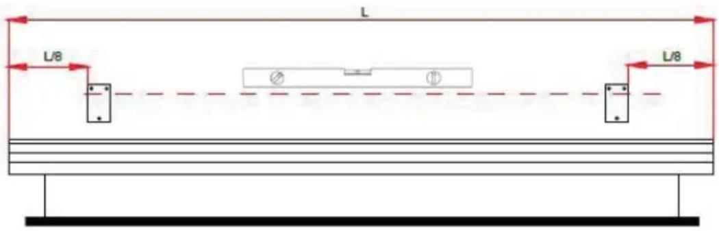
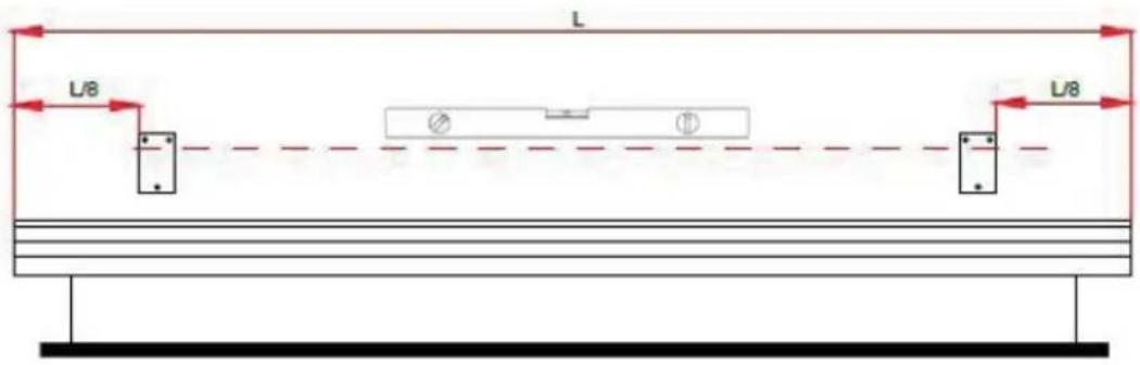
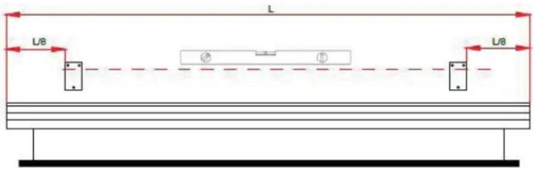
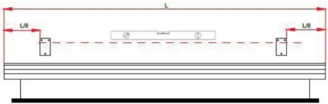
L L/8 L/8Measure the length of the casing and divide this value by 8 and place the mounting brackets according to the drawing above.
Draw a line to bring the two mounting brackets in alignment. Use the mounting brackets as a guide and mark the holes on the ceiling with a pencil. Then drill holes according to the marked holes with a drill and insert suitable dowels into the holes (the dowels must be firmly seated in the holes). Fasten the mounting brackets to the ceiling with suitable screws.
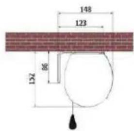
text_image
148 123 132 861
2
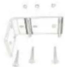
natural_image
Simple line drawing of a mechanical component with mounting holes (no text or symbols)SUSPENSION
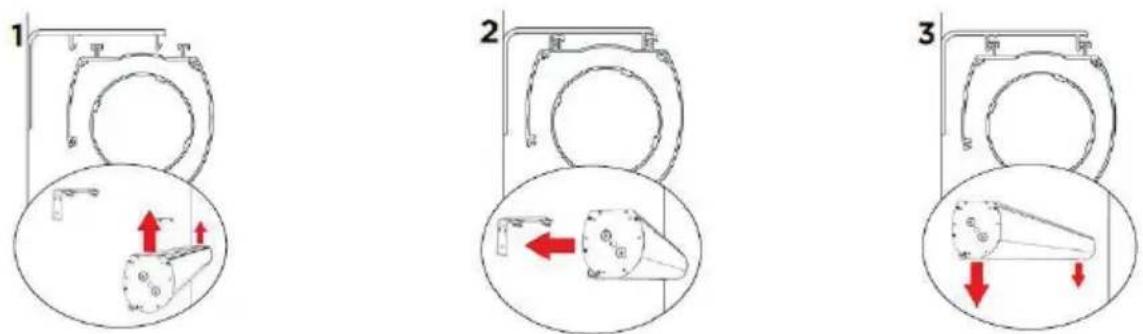
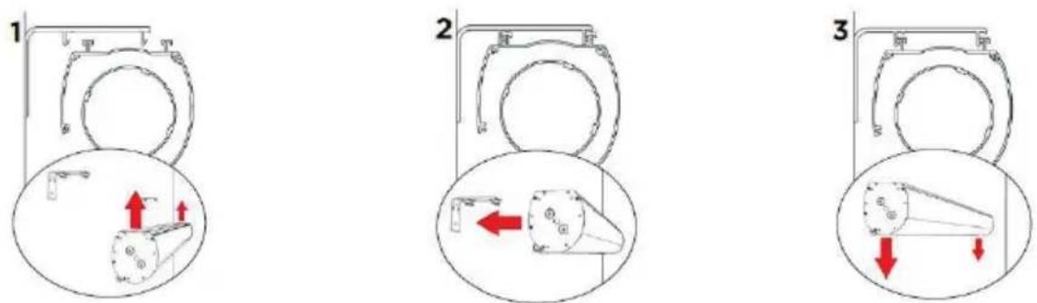
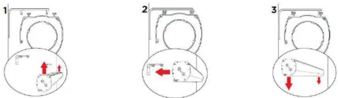
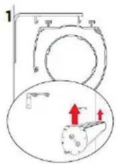
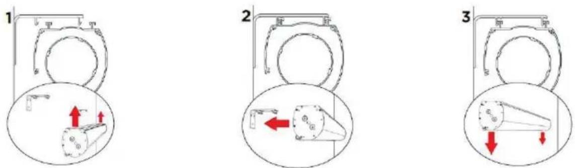
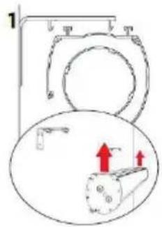
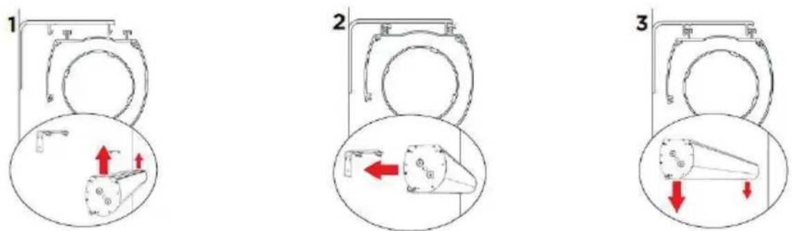
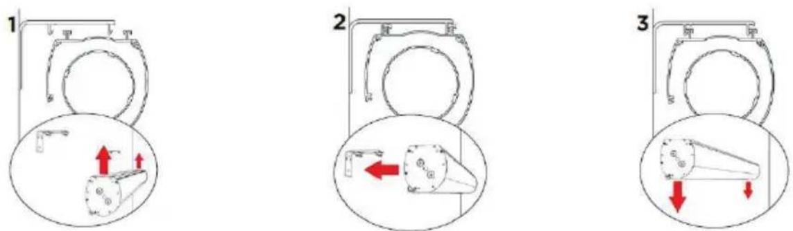
Lift the screen housing with two people and insert it into the mounting brackets. Make sure that the housing profiles hook into the mounting brackets. Now let the case slide slowly downwards and only let go when you are sure that the screen is securely in the bracket.
IMPORTANT NOTICE
text_image
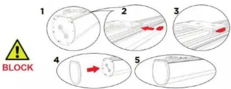
1 2 3 4 BLOCK 5Safe installation is only guaranteed if the enclosed plastic safety catches (shown in red in the picture above) are inserted into each mounting bracket from the front as shown in the drawing above. It is important that they lock noticeably when inserted.
Important: If there are not enough of these plastic safety catches, do not operate the screen. Contact your specialist dealer or celexon directly for a replacement.
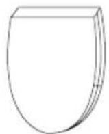
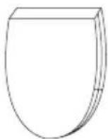
Press the side caps onto the screen housing - the assembly is complete.
INFORMATION ON EU CONFORMITY
Manufacturer: celexon Europe GmbH
Address: Gutenbergstraße 2, 48282 Emsdetten, DE
Product name: celexon Electric Chroma Key Green Screen
Products that are marked with the CE mark meet all requirements of the relevant EU directives. The EU declaration of conformity can be downloaded from the following address: www.celexon.de/zertifikate
The symbol indicates the separate collection of electrical and electronic devices in EU countries. Please do not throw the device into household waste. Find out about the return system applicable in your country and contact your local authority or your local waste and pollutant collection point if you have any questions about the disposal process.
INFORMATION ON UK CONFORMITY
Manufacturer: celexon Europe GmbH
Address: Gutenbergstraße 2, 48282 Emsdetten, DE
Product name: celexon Electric Chroma Key Green Screen
Products that are marked with the UKCA mark meet all requirements of the relevant UK directives. The UK declaration of conformity can be downloaded from the following address: www.celexon.de/zertifikate
The symbol indicates the separate collection of electrical and electronic devices in EU countries. Please do not throw the device into household waste. Find out about the return system applicable in your country and contact your local authority or your local waste and pollutant collection point if you have any questions about the disposal process.
natural_image
Solid green rectangular panel with black scroll wheel, no text or symbols visibleConsommation: 130 W (MAX)
0,4 W (en veille)

text_image
3 x 1,5 mm 2 4 x 0,75 mm 2 3 x 1,5 mm 2natural_image
Solid green rectangular panel with black border (no text or symbols)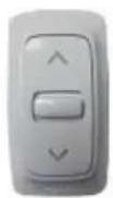
natural_image
Isometric line drawing of a metal bracket with mounting holes (no text or symbols)natural_image
Simple L-shaped line drawing with no text, numbers, or symbolsnatural_image
Diagram of a rectangular device with internal wiring and connectors, labeled with number 1 (no text or symbols on the diagram itself)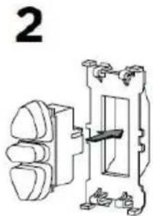
natural_image
Technical line drawing of a mechanical switch or electrical component with no visible text or symbols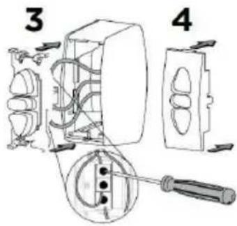
text_image
Technical diagram showing installation of a wall-mounted electrical switch with labeled parts 3 and 4MONTAGE SUR UN MUR (VISSÉ)
text_image
L L/8 L/8natural_image
Technical line drawing of a mechanical bracket with multiple screw fasteners (no text or symbols)MONTAGE AU PLAFOND (VISSÉ)
text_image
L L/8 Ø L/8natural_image
Simple line drawing of a mechanical component with mounting holes (no text or symbols)ÉQUERRES DE MONTAGE
text_image
1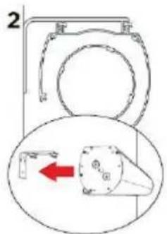
text_image
2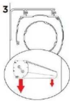
text_image
3 原 原natural_image
Solid green rectangular panel with black scroll wheel, no text or symbols visiblenatural_image
Solid green rectangular image with no visible text, symbols, or features.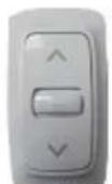
natural_image
Isometric line drawing of a metal bracket with mounting holes (no text or symbols)natural_image
Simple L-shaped line drawing with no text, numbers, or symbolsnatural_image
Diagram of a device with multiple wires and connectors, no text or symbols present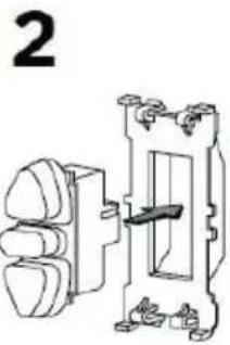
natural_image
Technical line drawing of a mechanical switch or fuse assembly (no text or symbols)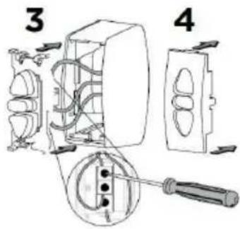
text_image
Technical diagram showing installation of a wall-mounted electrical switch with labeled parts 3 and 4MONTAJE EN PARED (ATORNILLADO)
text_image
L L/8 L/8natural_image
Technical line drawing of a mechanical bracket with multiple screw fasteners (no text or symbols)MONTAJE EN TECHO (ATORNILLADO)
text_image
L L/8 L/8natural_image
Simple line drawing of a mechanical component with pins and mounting holes (no text or symbols)SOPORTES DE MONTAJE
natural_image
Solid green rectangular panel with black horizontal band at top (no text or symbols)natural_image
Solid green square with black top border (no text or symbols)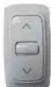

natural_image
Technical line drawing of a metal bracket with mounting holes (no text or symbols)natural_image
Simple L-shaped line drawing with no text, numbers, or symbolsnatural_image
Diagram of a mechanical or electrical component with multiple wires and connectors (no text or symbols)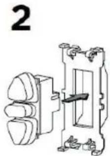
natural_image
Technical line drawing of a mechanical switch or electrical component with no visible text or symbols
text_image
Technical diagram showing installation of a wall-mounted electrical switch with labeled parts 3 and 4text_image
L L/8 L/8natural_image
Technical line drawing of a mechanical bracket with multiple screw fasteners (no text or symbols)text_image
L L/8 L/8natural_image
Simple line drawing of a mechanical component with mounting holes (no text or symbols)SOSPENSIONE
text_image
1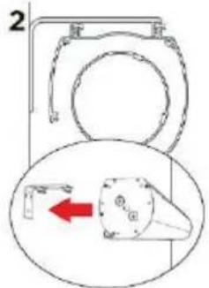
text_image
2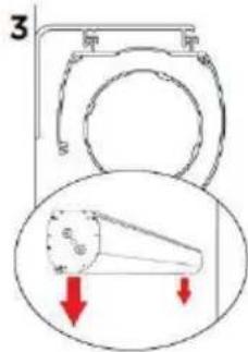
text_image
3natural_image
Green rectangular panel with black scroll wheel, no text or symbols visiblenatural_image
Solid green square with black horizontal bar at top (no text or symbols)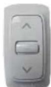

natural_image
Technical line drawing of a metal bracket with mounting holes (no text or symbols)natural_image
Simple L-shaped line drawing with no text, numbers, or symbolsnatural_image
Diagram of a mechanical or electrical component with multiple wires and connectors (no text or symbols)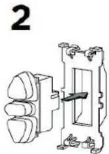
natural_image
Technical line drawing of a mechanical switch or electrical component with no visible text or symbols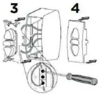
text_image
Technical diagram showing installation of a wall-mounted electrical switch with labeled parts 3 and 4MONTAŻ NA ŚCIANIE (WARIANT PRZYKREÇANY)
text_image
L L/8 L/8natural_image
Technical line drawing of a mechanical bracket with multiple screw fasteners (no text or symbols)MONTAŻ NA SUFICIE (WARIANT PRZYKREÇANY)
text_image
L L/8 L/8natural_image
Simple line drawing of a mechanical component with mounting holes (no text or symbols)ZAWIESZANIE
natural_image
Solid green rectangular panel with black scroll wheel, no text or symbols visiblenatural_image
Solid green square with black border (no text or symbols)natural_image
Technical line drawing of a metal bracket with mounting holes (no text or symbols)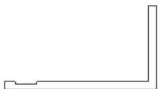
natural_image
Simple L-shaped line drawing with no text, numbers, or symbols2x kunststof borging
natural_image
Diagram of a mechanical or electrical component with multiple wires and connectors (no text or symbols)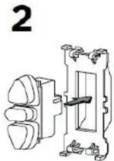
natural_image
Technical line drawing of a mechanical switch or electrical component with no visible text or symbols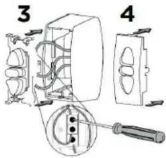
text_image
Technical diagram showing installation of a wall-mounted electrical switch with labeled parts 3 and 4WANDMONTAGE (VASTGESCHROEFD)
text_image
L L/8 L/8natural_image
Technical line drawing of a mechanical bracket with multiple screw fasteners (no text or symbols)PLAFONDMONTAGE (VASTGESCHROEFD)
text_image
L L/8 L/8natural_image
Simple line drawing of a mechanical component with mounting holes (no text or symbols)OPHANGING
natural_image
Solid green rectangular panel with black scroll wheel, no text or symbols visiblenatural_image
Solid green rectangular image with a black horizontal bar at the top (no text or symbols)
natural_image
Isometric line drawing of a metal bracket with mounting holes (no text or symbols)natural_image
Simple L-shaped line drawing with no text, numbers, or symbols2x Plastsäkring
MONTERINGSANVISNING
natural_image
Diagram of a mechanical or electrical component with multiple wires and connectors (no text or symbols)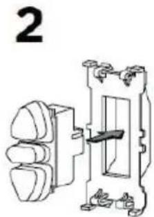
natural_image
Technical line drawing of a mechanical switch or electrical component with no visible text or symbols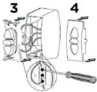
text_image
Technical diagram showing installation of a wall-mounted electrical switch with labeled parts 3 and 4VÄGGMONTERING (SKRUVAD)
text_image
L L/8 L/8natural_image
Technical line drawing of a mechanical bracket with multiple screw fasteners (no text or symbols)TAKMONTERING (SKRUVAD)
text_image
L L/8 L/8natural_image
Simple line drawing of a mechanical component with mounting holes (no text or symbols)MONTERINGSFÄSTE