
PWS-110PR1 - Server SONY - Free user manual and instructions
Find the device manual for free PWS-110PR1 SONY in PDF.

User questions about PWS-110PR1 SONY
0 question about this device. Answer the ones you know or ask your own.
Ask a new question about this device
Download the instructions for your Server in PDF format for free! Find your manual PWS-110PR1 - SONY and take your electronic device back in hand. On this page are published all the documents necessary for the use of your device. PWS-110PR1 by SONY.
USER MANUAL PWS-110PR1 SONY
Japanese/English/French/German/Italian/Spanish/Chinese/Korean
1st Edition (Revised 5)
目次
概要 3
必要な機器....3
システム構成と接続....3
各部の名称と働き 4
前面 4
前面(パネルを外した場合)……4
背面 5
準備 6
初期設定....6
PWS-4500/PWS-4400/BPU4800の設定....6
PWA-MGW1 の設定....6
アプリケーションの起動と終了……7
アプリケーションの設定……7
システムの設定....7
メンテナンスアプリケーションの操作 7
使用上のご注意....8
仕様 8
①FAN インジケーター
① SYSTEM TC 端子
本システムでは使用しません。
System Configuration and Connection 11
Name and Function of Parts....12
Front View 12
Front View (Panel Removed).... 12
Rear View.... 13
Setting Up.... 14
Initial Settings 14
PWS-4500/PWS-4400/BPU4800 Settings.... 14
PWA-MGW1 Settings 14
Starting and Exiting the Application.... 15
Application Settings.... 15
System Settings 15
Maintenance Web Application Operation.... 15
Usage Precautions 16
Specifications 16
For safety, please read the precautions described in the PWS-100 PWS-110 Operation Guide (supplied).
Overview
The PWS-110PR1 is a system for controlling a PWS-4500/PWS-4400 Multi Port AV Storage Unit or BPU4800 Baseband Processor Unit using PWA-PRC1 Production Control Software to perform functions, such as controlling slow-motion playback of live video and managing clips and playlists.
The unit connects to a PWSK-4403 USB Control Device to control operation using buttons, fader lever, and jog dial. It can control slow-motion playback speed, search for video images, cue marked positions, perform cutout edits, and control other functions while monitoring the video displayed on a monitor. It also enables created clips to be selected from a list for playback or copying, and for registering in a playlist for highlight editing.
For details about operation, refer to the PWA-PRC1 User's Guide.
Required Devices
The following devices are required for unit operation.
- PWS-4500/PWS-4400 Multi Port AV Storage Unit or BPU4800 Baseband Processor Unit
• PWSK-4403 USB Control Device
System Configuration and Connection
The SDI connectors and a LAN connector of the unit connect to a PWS-4500/PWS-4400/BPU4800, and a PWSK-4403 connects to a USB port of the unit.
Notice to customers
Installation of the unit should be performed by your Sony service personnel or a technician who has received service training.
Name and Function of Parts
Front View
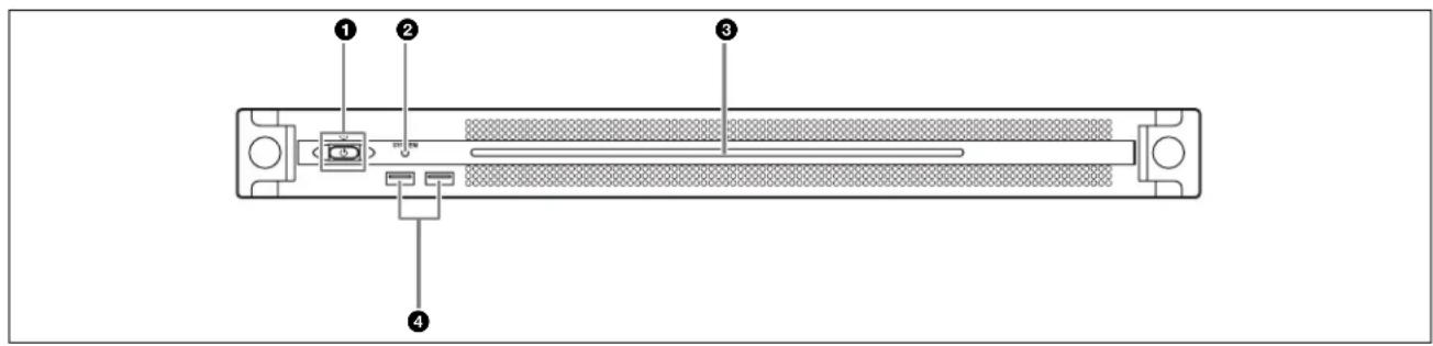
①On/Standby button and indicator
Switches the unit on/off (standby state). Connecting the power cord places the unit in standby state, and the indicator turns on red. Pressing the On/Standby button while in standby state turns on the unit and the indicator turns on green. Pressing and holding the On/Standby button for two seconds switches the unit to standby state, and the indicator changes to red. To turn the unit on again after switching from On state to standby state, when the indicator is red, press and hold the On/Standby button for three seconds or longer. The indicator goes out when the power cord is disconnected.
② SYSTEM indicator
Indicates the status of the unit.
Green: Operating normally
Flashing green (once per second): System is booting or transitioning to standby state.
Flashing orange (once per second): A warning has been generated.
High-speed flashing read (four times per second): An error has occurred.
③Front panel LED
Turns on according to settings in the web application. The LED is configured using [001: LINE LED] in the [Settings] page on the Maintenance screen.
④USB connectors (front panel)
Connects to a keyboard and mouse for initializing the unit. USB devices not described in this document are not supported.
Notes
- Both USB ports on the front panel support power delivery (900 mA).
- Use SuperSpeed USB cables.
Front View (Panel Removed)
When the SYSTEM indicator or web application indicates an error, you can remove the front panel to check the status of the hardware components.
To remove the front panel, loosen the screws on the left and right sides and pull the panel towards you.
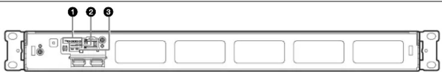
①FAN indicators
If any of the fans fail, the corresponding fan indicator turns on red.
② POWER indicators
If either of the AC power supply units fail, the corresponding indicator turns on red.
③TEMP indicator
If an abnormally high temperature is detected within the unit, the indicator turns on red.
Rear View
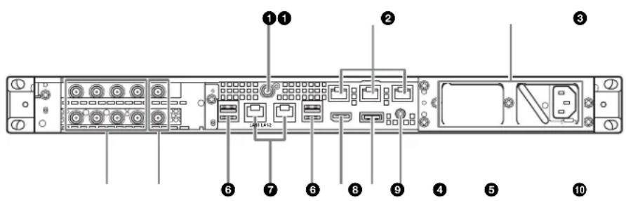
① SYSTEM TC connector
Not used by this system.
② Remote connectors (1/2, 3/4, 5)
Not used by this system.
③AC power supply units
Insert the power cords and connect to power outlets. Only one AC power supply unit is installed at the factory. A second optional power supply unit can be installed to provide power supply redundancy. When used in systems that require reliability, power supply redundancy allows the unit to continue operating even if a power supply unit fails.
For details about installing or replacing a power supply unit, consult your Sony sales or service representative.
④SDI (1 to 4) connectors
SDI1 to SDI4 connectors are numbered from left to right. Connect to a PWS-4500/PWS-4400/BPU4800 using an SDI cable to input SDI signals.
⑤REF IN connectors
Not used by this system.
⑥USB connectors (rear panel)
Connect to a PWSK-4403 using a USB cable.
Notes
- Of the four USB connectors on the rear panel, only the bottom right port supports power delivery (900 mA). The other three ports do not support power delivery, and should be used to connect USB devices that do not require power supplied from the USB connector.
- Use SuperSpeed USB cables.
⑦ LAN connectors
Connect to a Gigabit Ethernet network.
⑧HDMI connector
Connect to a monitor using an HDMI cable.
Use an HDMI cable that conforms to the following standard.
• High Speed HDMI Cable (Premium High Speed HDMI Cable)
⑨DisplayPort connector
Connect to a monitor using a DisplayPort-to-DVI converter cable or DisplayPort-to-HDMI converter cable. Use an active-type converter cable.
Note
Use a DisplayPort cable that conforms to the following standard.
• DP v1.2a (compliant)
⑩Ground terminal
Connect to ground.
Setting Up
Initial Settings
Before using the unit, configure the Windows settings within the unit. The description below describes the standard settings in Windows.
Note
To reboot the unit, first shut down the unit and then turn the On/Standby button on the front panel on again, without rebooting Windows.
1 Connect a keyboard and mouse to the USB connectors on the front panel, and connect a monitor to the DisplayPort connector or HDMI connector on the rear panel.
2 Turn the On/Standby button on.
3 When the Windows login screen appears, enter "prc" as the user name and "prc" as the password.
4 When the password setup screen appears, configure a new password and log in.
Configuring the network
1 Connect a LAN cable to the LAN connector on the rear panel of the unit, and connect the other end to the network.
2 Click [View network status and tasks] under [Network and Internet] in the control panel.
3 Click the device connected by LAN cable in [Connections].
4 Click the [Properties] button.
5 Select [Internet Protocol Version 4 (TCP/IPv4)], then click the [Properties] button.
6 Change the IP address and other settings.
7 Click the [Advanced] button to configure DNS, WINS, and other settings.
8 When finished, click the [OK] button.
Setting the date and time
1 Select [Set the time and date] under [Date and Time] in the [Clock, Language, and Region] control panel.
2 Click [Change time zone] on the [Date and Time] tab, and select the time zone.
3 Click [Change date and time] on the [Date and Time] tab, and set the date and time.
4 Click the [Change settings] button on the [Internet Time] tab.
5 Specify an NTP server, then click the [Update Now] button.
6 Place a check mark in [Synchronize with an Internet time server] to periodically correct the clock using the NTP server.
Signing out
When finished, sign out from Windows.
1 Move the mouse cursor to the top right corner of the screen to display the Charms bar, then click [Start].
2 Click the account name on the top right of the screen, then click [Sign out].
PWS-4500/PWS-4400/BPU4800 Settings
Configure the input/output port settings on the PWS-4500/PWS-4400/BPU4800.
For details about configuration, refer to the PWA-PRC1 Installation Guide, and the PWS-4500/PWS-4400/BPU4800 Operation Manual.
PWA-MGW1 Settings
Configure settings in PWA-MGW1 Media Gateway Software to enable archiving to media.
For details about configuration, refer to the PWA-PRC1 Installation Guide, and the Help in PWA-MGW1.
Starting and Exiting the Application
Starting PWA-PRC1
For details about starting the application, refer to the PWA-PRC1 User's Guide.
1 Turn on the PWSK-4403 and PWS-4500/PWS-4400/BPU4800 connected to the unit, then turn on the unit.
2 Click "PWA-PRC1" on the Start screen or double-click the "PWA-PRC1" icon on the desktop.
Exiting PWA-PRC1
For details about exiting the application, refer to the PWA-PRC1 User's Guide.
Application Settings
Launch the application and configure the required system settings.
For details about configuration, refer to "Configuration" in the PWA-PRC1 User's Guide.
System Settings
Configure the system settings on the Maintenance screen in the web application.
For details about the Maintenance screen, see "Maintenance Web Application Operation" on page 15.
Maintenance Web Application Operation
For details about the operation of the Maintenance Web Application for system administrators, log in to the unit and click the shortcut icon on the desktop to refer to the Operation Manual.
Usage Precautions
Power supply precautions
If the unit is suddenly turned off during operation, data loss may occur. To maintain data integrity, the use of an uninterruptible power supply (UPS) is recommended. To disconnect the power cord or turn off the breaker, always press the On/Standby button on the unit to stop the unit before proceeding.
USB device precautions
The unit does not support UASP (USB Attached SCSI Protocol).
Specifications
General
Power requirements
$$ 1 0 0 \mathrm{V} \text { to } 2 4 0 \mathrm{V} \mathrm{AC} $$
$$ 5 0 / 6 0 \mathrm{Hz} $$
Power consumption
$$ 2 3 5 \mathrm{W} $$
Standby power consumption
$$ 3 \text { W or lower } $$
Operating temperature
$$ 5 ^ {\circ} \mathrm{C} \text { to } 3 5 ^ {\circ} \mathrm{C} (4 1 ^ {\circ} \mathrm{F} \text { to } 9 5 ^ {\circ} \mathrm{F}) $$
Storage temperature
$$ - 2 0 ^ {\circ} \mathrm{C} \text {to} + 6 0 ^ {\circ} \mathrm{C} (- 4 ^ {\circ} \mathrm{F} \text {to} + 1 4 0 ^ {\circ} \mathrm{F}) $$
Operating humidity
$$ 20 \% \text{ to } 90 \% \text{(relative humidity)} $$
Storage humidity 5% to 80%
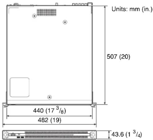
Mass 10.2 kg (22 lb. 7.8 oz.)
Dimensions 440× 43.6× 507mm(17^3 / _8× 1^3 / _4×
$$ 2 0 \text { in. } (\text { width / height / depth }) $$
CPU
Processor Intel Core i7 6700TE (2.4 GHz)
Memory 8 GBytes
$$ \text { SO - DIMM } (\text { DDR4 }) (2) $$
Drive (M.2) 120 GBytes
Expansion bus PCIe Gen2 8Lane (30 W) (2)
Inputs/outputs
LAN RJ-45 (2)
$$ 1 0 0 0 \text { B A S E - T } $$
$$ 1 0 0 \text { B A S E - T X } $$
USB (front panel/rear panel)
$$ \text { Super Speed USB(USB3.0)TypeA } $$
$$ (6, 2 \text { on front and } 4 \text { on rear }) $$
Front: Power delivery support (900 mA/port)
Rear: Power delivery support on bottom
right port (900 mA), not supported on
$$ \text { other three ports } $$
HDMI Type A (1)
$$ \text { H D M I V e r . } 1. 4 \mathrm{a}, $$
$$ 1 9 2 0 \times 1 2 0 0 \text { maximum resolution, } 6 0 \mathrm{Hz} $$
DisplayPort DisplayPort (1)
DisplayPort Ver. 1.1a,
2560×1600 maximum resolution, 60 Hz
REF IN BNC (2)
SMPTE ST 318 compliant, HD tri-level
sync (0.6 Vp-p/75 Ω/sync load) or SD
black burst/composite sync
(0.286 Vp-p/75 Ω/sync load)
SDI 1 to 4 BNC (8)
HD: SMPTEST292-1 complian
SD: SMPTE ST 259 compliant
Supplied accessories
Operation Manual (this document) (1)
Operation Guide (1)
Rack mount screws (4)
Optional accessories
PWSK-101 Optional Power Supply
Design and specifications are subject to change without notice.
Depending on the operating environment, unauthorized third parties on the network may be able to access the unit. When connecting the unit to the network, be sure to confirm that the network is protected securely.
Notes
• Always make a test recording, and verify that it was recorded successfully.
SONY WILL NOT BE LIABLE FOR DAMAGES OF ANY KIND INCLUDING, BUT NOT LIMITED TO, COMPENSATION OR REIMBURSEMENT ON ACCOUNT OF FAILURE OF THIS UNIT OR ITS RECORDING MEDIA, EXTERNAL STORAGE SYSTEMS OR ANY OTHER MEDIA OR STORAGE SYSTEMS TO RECORD CONTENT OF ANY TYPE.
• Always verify that the unit is operating properly before use. SONY WILL NOT BE LIABLE FOR DAMAGES OF ANY KIND INCLUDING, BUT NOT LIMITED TO, COMPENSATION OR REIMBURSEMENT ON ACCOUNT OF THE LOSS OF PRESENT OR PROSPECTIVE PROFITS DUE TO FAILURE OF THIS UNIT, EITHER DURING THE WARRANTY PERIOD OR AFTER EXPIRATION OF THE WARRANTY, OR FOR ANY OTHER REASON WHATSOEVER.
- SONY WILL NOT BE LIABLE FOR CLAIMS OF ANY KIND MADE BY USERS OF THIS UNIT OR MADE BY THIRD PARTIES.
- SONY WILL NOT BE LIABLE FOR THE LOSS, REPAIR, OR REPRODUCTION OF ANY DATA RECORDED ON THE INTERNAL STORAGE SYSTEM, RECORDING MEDIA, EXTERNAL STORAGE SYSTEMS OR ANY OTHER MEDIA OR STORAGE SYSTEMS.
- SONY WILL NOT BE LIABLE FOR THE TERMINATION OR DISCONTINUATION OF ANY SERVICES RELATED TO THIS UNIT THAT MAY RESULT DUE TO CIRCUMSTANCES OF ANY KIND.
- Windows is a registered trademark of Microsoft Corporation in the United States and other countries. Other products or system names appearing in this document are trademarks or registered trademarks of their respective owners. Further, the ®, or ™ symbols are not used in the text.
This Product uses the Source Code of T-Kernel 2.0 under T-License 2.1 granted by TRON Forum (www.tron.org).
For the customers in Taiwan
①Indicateurs FAN
PCIe Gen2 8Lane (30 W) (2)
Entrées/Sorties
LAN RJ-45 (2)
1000BASE-T
100BASE-TX
①FAN-LEDs
PCIe Gen2 8Lane (30 W) (2)
Eingänge/Ausgänge
LAN RJ-45 (2)
1000BASE-T
100BASE-TX
①Indicatori FAN
PCIe Gen2 8Lane (30 W) (2)
Ingressi/uscite
LAN RJ-45 (2)
1000BASE-T
100BASE-TX
①Indicadores FAN
①Conector SYSTEM TC
• Utilice cables USB SuperSpeed.
⑦Conectores LAN
Conéctese a una red Gigabit Ethernet.
⑧Conector HDMI
PCIe Gen2 8Lane (30 W) (2)
Entradas/salidas
LAN RJ-45 (2)
1000BASE-T
100BASE-TX
USB (panel frontal/panel posterior)
①开机 / 待机键和指示灯
①FAN 指示灯
① SYSTEM TC 接口
本系统未使用。
•PWS-4500/PWS-4400 Multi Port AV Storage Unit 또는 BPU4800 Baseband Processor Unit
•PWSK-4403 USB Control Device
시스템 구성 및 연결
①FAN 표시등

① SYSTEM TC 커넥터
이 시스템에서는 사용되지 않습니다.
DisplayPort 버전.1.1a,
The material contained in this manual consists of information that is the property of Sony Corporation and is intended solely for use by the purchasers of the equipment described in this manual.
Sony Corporation expressly prohibits the duplication of any portion of this manual or the use thereof for any purpose other than the operation or maintenance of the equipment described in this manual without the express written permission of Sony Corporation.

- 目次
- 概要 3
- 各部の名称と働き 4
- 準備 6
- メンテナンスアプリケーションの操作 7
- 使用上のご注意....8
- 仕様 8
- ①FAN インジケーター
- ① SYSTEM TC 端子
- Name and Function of Parts....12
- Setting Up.... 14
- Maintenance Web Application Operation.... 15
- Usage Precautions 16
- Specifications 16
- Overview
- Required Devices
- System Configuration and Connection
- Notice to customers
- Name and Function of Parts
- ①On/Standby button and indicator
- ② SYSTEM indicator
- ③Front panel LED
- ④USB connectors (front panel)
- Notes
- Front View (Panel Removed)
- ①FAN indicators
- ② POWER indicators
- ③TEMP indicator
- Rear View
- ① SYSTEM TC connector
- ② Remote connectors (1/2, 3/4, 5)
- ③AC power supply units
- ④SDI (1 to 4) connectors
- ⑤REF IN connectors
- ⑥USB connectors (rear panel)
- ⑦ LAN connectors
- ⑧HDMI connector
- ⑨DisplayPort connector
- Note
- ⑩Ground terminal
- Setting Up
- Initial Settings
- Configuring the network
- Setting the date and time
- Signing out
- PWS-4500/PWS-4400/BPU4800 Settings
- PWA-MGW1 Settings
- Starting and Exiting the Application
- Starting PWA-PRC1
- Exiting PWA-PRC1
- Application Settings
- System Settings
- Maintenance Web Application Operation
- Usage Precautions
- Power supply precautions
- USB device precautions
- Specifications
- General
- CPU
- Inputs/outputs
- Supplied accessories
- Optional accessories
- ①Indicateurs FAN
- Entrées/Sorties
- ①FAN-LEDs
- Eingänge/Ausgänge
- ①Indicatori FAN
- Ingressi/uscite
- ①Indicadores FAN
- ①Conector SYSTEM TC
- ⑦Conectores LAN
- ⑧Conector HDMI
- Entradas/salidas
- ①开机 / 待机键和指示灯
- ①FAN 指示灯
- ① SYSTEM TC 接口
- 시스템 구성 및 연결
- ①FAN 표시등
- ① SYSTEM TC 커넥터
Brand : SONY
Model : PWS-110PR1
Category : Server