PVM-2551MD - Monitor SONY - Free user manual and instructions
Find the device manual for free PVM-2551MD SONY in PDF.

User questions about PVM-2551MD SONY
0 question about this device. Answer the ones you know or ask your own.
Ask a new question about this device
Download the instructions for your Monitor in PDF format for free! Find your manual PVM-2551MD - SONY and take your electronic device back in hand. On this page are published all the documents necessary for the use of your device. PVM-2551MD by SONY.
USER MANUAL PVM-2551MD SONY
Professional Video Monitor
取扱説明書 2 ベージ ____ J
Instructions for Use Page 44 GB
http://www.sony.net/Printed in China
© 2012 Sany Corporation

安全のために
text_image
Diagram of a tablet device with labeled ports and connectors, showing numbered labels from 1 to 12.①タリーランプ
text_image
Diagram of a computer rear panel with numbered ports and labeled connectors①/▽(等電位/機能アース) 端子
(等電位) 端子
等電位プラグを接続します。
± (機能アース) 端子
アース線を接続します。
natural_image
Line drawing of a plug inserted into a socket (no text or symbols)natural_image
Technical line drawing of a device panel with an inset showing internal components (no text or symbols)電源コードをはずすには
natural_image
Technical diagram of a mechanical component with screwdriver and adjustment knob (no text or symbols)natural_image
Technical line drawing of a mechanical assembly with mounting holes and a highlighted component (no text or symbols)3 ネジで止める。
natural_image
Technical line drawing of a mechanical component with a screwdriver inserted, showing internal parts and a rotation arrow (no text or symbols)端子カバーの取りはずしかた
text_image
World map with numbered regions highlighting major continents and key countriesnatural_image
Outline map of East Asia and surrounding countries, highlighting the Philippines (no text or labels)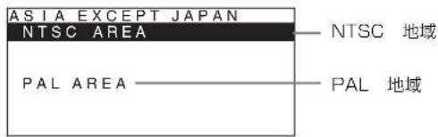
APA (Auto Pixel Alignment)
DC OUT: 24 V 5.0 A 5 V 0.060 A
消費電力 約 135 W (最大)
European Representative (欧州代理人) [Non-Text]
別売アクセサリー
SDI 4:2:2 入力アダプター
BKM-220D
HD/D1-SDI 入力アダプター
BKM-243HSM
NTSC/PAL 入力アダプター
BKM-227W
アナログコンポーネント人力アダプター
BKM-229X
Before operating the unit, please read this manual thoroughly and retain it for future reference.
Owner's Record
The model and serial numbers are located at the rear. Record these numbers in the spaces provided below. Refer to these numbers whenever you call upon your Sony dealer regarding this product.
Model No. ____ Serial No. ____
Indications for Use/Intended Use
The Sony PVM-2551MD/PVM-2551NB OLED Monitor is intended to provide color video displays of images from surgical camera systems. The PVM-2551MD/PVM-2551NB is a widescreen, high-definition monitor for real-time use during minimally invasive surgical procedures including arthroscopy (orthopedic surgery), laparoscopy (general and gynecological surgery), thoracoscopy, endoscopy (general, gastroenterological and ENT surgery) and general surgery.
WARNING
To reduce the risk of fire or electric shock, do not expose this apparatus to rain or moisture.
To avoid electrical shock, do not open the cabinet. Refer servicing to qualified personnel only.
No modification of this apparatus is allowed.
WARNING
THIS APPARATUS MUST BE EARTHED.
WARNING
To disconnect the main power, unplug the AC plug. When installing the unit, incorporate a readily accessible disconnect device in the fixed wiring, or connect the power plug to an easily accessible socket-outlet near the unit. If a fault should occur during operation of the unit, operate the disconnect device to switch the power supply off, or disconnect the power plug.
CAUTION
This video monitor should only be used with a specified monitor stand. For information on suitable stands, refer to “Specifications.” Installation of the video monitor on any other stand may result in instability, possibly leading to injury.
WARNING
Make sure the surface is wide enough so that this apparatus's width and depth don't exceed the surface's edges.
If not, this apparatus may lean or fall over and cause an injury.
Consult with Sony qualified personnel for mounting arm, wall or ceiling mount installation.
CAUTION
The apparatus shall not be exposed to dripping or splashing. No objects filled with liquids, such as vases, shall be placed on the apparatus.
Do not install the appliance in a confined space, such as book case or built-in cabinet.
Caution
When you dispose of the unit or accessories, you must obey the laws in the relative area or country and the regulations in the relative hospital.
CAUTION
The unit is not disconnected from the AC power source (mains) as long as it is connected to the wall outlet, even if the unit itself has been turned off.
For the customers in the U.S.A.
This equipment has been tested and found to comply with the limits for a Class A digital device, pursuant to Part 15 of the FCC Rules. These limits are designed to provide reasonable protection against harmful interference when the equipment is operated in a commercial environment. This equipment generates, uses, and can radiate radio frequency energy and, if not installed and used in accordance with the instruction manual, may cause harmful interference to radio communications. Operation of this equipment in a residential area is likely to cause harmful interference in which case the user will be required to correct the interference at his own expense.
You are cautioned that any changes or modifications not expressly approved in this manual could void your authority to operate this equipment.
All interface cables used to connect peripherals must be shielded in order to comply with the limits for a digital device pursuant to Subpart B of Part 15 of FCC Rules.
This device complies with Part 15 of the FCC Rules. Operation is subject to the following two conditions: (1) this device may not cause harmful interference, and (2) this device must accept any interference received, including interference that may cause undesired operation.
For the customers in Canada
This Class A digital apparatus complies with Canadian ICES-003.
This unit has been certified according to Standard CAN/CSA-C22.2 No. 60601-1.
For the customers in the U.S.A and Canada
When you use this product connected to 240 V single phase, be sure to connect this product to a center tapped circuit.
WARNING:
Using this unit at a voltage other than 120 V may require the use of a different line cord or attachment plug, or both. To reduce the risk of fire or electric shock, refer servicing to qualified service personnel.
Symbols on the unit
| Symbol | Location This symbol indicates | |
 | Bottom Power switch. Press to turn the monitor on. | |
 | Bottom Power switch. Press to turn the monitor off. | |
 | Rear The equipotential terminal which brings the various parts of a system to the same potential. | |
 | Rear Functional earth terminal | |
 | Front Key inhibit | The setting are locked so that they cannot be changed. |

This symbol is located on the rear of the unit. See page 61 of these instructions for details about how to remove, or attach the connector cover.

Refer to the operating instructions
Follow the directions in the operating instructions for parts of the unit on which this mark appears.

This symbol indicates the manufacturer, and appears next to the manufacturer's name and address.

This symbol indicates the European Community representative, and appears next to the European Community representative's name and address.
WARNING on power connection
Use a proper power cord for your local power supply.
-
Use the approved Power Cord (3-core mains lead) / Appliance Connector / Plug with earthing-contacts that conforms to the safety regulations of each country if applicable.
-
Use the Power Cord (3-core mains lead) / Appliance Connector / Plug conforming to the proper ratings (Voltage, Ampere).
If you have questions on the use of the above Power Cord / Appliance Connector / Plug, please consult a qualified service personnel.
WARNING on power connection for medical use
Please use the following power supply cord. With connectors (plug or female) and cord types other than those indicated in this table, use the power supply cord that is approved for use in your area.
| United States and Canada | |
| Plug Type HOSPITAL GRADE* | |
| Cord Type Min. Type SJTMin. 18 AWG | |
| Minimum Rating for Plug and Appliance Couplers | 10A/125V |
| Safety Approval UL | Listed and CSA |
*Note: Grounding reliability can only be achieved when the equipment is connected to an equivalent receptacle marked 'Hospital Only' or 'Hospital Grade'.
Important safeguards/notices for use in the medical environments
-
All the equipments connected to this unit shall be certified according to Standard IEC60601-1, IEC60950-1, IEC60065 or other IEC/ISO Standards applicable to the equipments.
-
Furthermore all configurations shall comply with the system standard IEC60601-1-1.
Everybody who connects additional equipment to the signal input part or signal output part configures a medical system, and is therefore, responsible that the system complies with the requirements of the system standard IEC60601-1-1.
If in doubt, consult the qualified service personnel.
-
The leakage current could increase when connected to other equipment.
-
For this particular equipment, all accessory equipment connected as noted above, must be connected to mains via an additional isolation transformer conforming with the construction requirements of IEC60601-1 and providing at least Basic Insulation.
-
This equipment generates, uses, and can radiate radio frequency energy. If it is not installed and used in accordance with the instruction manual, it may cause interference to other equipment. If this unit causes interference (which can be determined by unplugging the power cord from the unit), try these measures: Relocate the unit with respect to the susceptible equipment. Plug this unit and the susceptible equipment into different branch circuit.
Consult your dealer. (According to standard IEC60601-1-2 and CISPR11, Class B, Group 1)
- Model PVM-2551MD/2551NB is a monitor intended for use in a medical environment to display pictures from cameras or other systems, other than diagnostic X-ray equipment.
Important EMC notices for use in the medical environments
- The PVM-2551MD/2551NB needs special precautions regarding EMC and needs to be installed and put into service according to the EMC information provided in this instructions for use.
- The portable and mobile RF communications equipment such as cellular phones can affect the PVM-2551MD/2551NB.
Warning
The use of accessories and cables other than those specified, with the exception of replacement parts sold by Sony Corporation, may result in increased emissions or decreased immunity of the PVM-2551MD/2551NB.
| Guidance and manufacturer's declaration-electromagnetic emissions | ||
| The PVM-2551MD/2551NB is intended for use in the electromagnetic environment specified below.The customer or the user of the PVM-2551MD/2551NB should assure that it is used in such an environment. | ||
| Emission test Compliance Electromagnetic environment-guidance | ||
| RF emissionsCISPR 11 | Group 1 | The PVM-2551MD/2551NB uses RF energy only for its internal function. Therefore, its RF emissions are very low and are not likely to cause any interference in nearby electronic equipment. |
| RF emissionsCISPR 11 | Class B | The PVM-2551MD/2551NB is suitable for use in all establishments, including domestic establishments and those directly connected to the public low-voltage power supply network that supplies buildings used for domestic purposes. |
| Harmonic emissionsIEC 61000-3-2 | Class D | |
| Voltage fluctuations/flicker emissionsIEC 61000-3-3 | Complies | |
Warning
If the PVM-2551MD/2551NB should be used adjacent to or stacked with other equipment, it should be observed to verify normal operation in the configuration in which it will be used.
| Guidance and manufacturer's declaration - electromagnetic immunity | |||
| The PVM-2551MD/2551NB is intended for use in the electromagnetic environment specified below. The customer or the user of the PVM-2551MD/2551NB should assure that it is used in such as environment. | |||
| Immunity test | IEC 60601 test level | Compliance level E | Electromagnetic environment - guidance |
| Electrostatic discharge (ESD)IEC 61000-4-2 | ±6 kV contact±8 kV air | ±6 kV contact±8 kV air | Floors should be wood, concrete or ceramic tile. If floors are covered with synthetic material, the relative humidity should be at least 30%. |
| Electrical fast transient/burstIEC 61000-4-4 | ±2 kV for power supply lines±1 kV for input/output lines | ±2 kV for power supply lines±1 kV for input/output lines | Mains power quality should be that of a typical commercial or hospital environment. |
| SurgeIEC 61000-4-5 | ±1 kV line(s) to linc(s)±2 kV line(s) to earth | ±1 kV differential mode±2 kV common mode | Mains power quality should be that of a typical commercial or hospital environment. |
| Voltage dips, short interruptions and voltage variations on power supply input linesIEC 61000-4-11 | < 5% UT(>95% dip in UT) for 0.5 cycle40% UT(60% dip in UT) for 5 cycles70% UT(30% dip in UT) for 25 cycles< 5% UT(>95% dip in UT) for 5 sec | < 5% UT(>95% dip in UT) for 0.5 cycle40% UT(60% dip in UT) for 5 cycles70% UT(30% dip in UT) for 25 cycles< 5% UT(>95% dip in UT) for 5 sec | Mains power quality should be that of a typical commercial or hospital environment. If the user of the PVM-2551MD/2551NB requires continued operation during power mains interruptions, it is recommended that the PVM-2551MD/2551NB be powered from an uninterruptible power supply or a battery. |
| Power frequency (50/60Hz) magnetic fieldIEC 61000-4-8 | 3 A/m 3 A/m Power frequency magnetic fields should be at least characteristic of a typical location in a typical commercial or hospital environment. | ||
| NOTE: UT is the a.c. mains voltage prior to application of the test level. | |||
| Immunity test | IEC 60601 test level | Compliance level | Electromagnetic environment - guidance |
| Conducted RF | 3 Vrms | 3 Vrms | Portable and mobile RF communications equipment should be used no closer to any part of the PVM-2551MD/2551NB, including cables, than the recommended separation distance calculated from the equation appliance to the frequency of the transmitter. |
| IEC 61000-4-6 | 150 kHz to 80 MHz | Recommended separation distance d = 1.2 d = 1.2 80MHzto 800MHz d = 2.3 800MHzto 2.5GHz | |
| Radiated RF | 3 V/m | 3 V/m | Where P is the maximum output power rating of the transmitter in watts (W) according to the transmitter manufacturer and d is the recommended separation distance in meters (m).Field strengths from fixed RF transmitters, as determined by an electromagnetic site survey, ^a should be less than the compliance level in each frequency range. ^b Interference may occur in the vicinity of equipment marked with following symbol: |
| IEC 61000-4-3 | 80 MHz to 2.5 GHz | ||
| NOTE 1: At 80 MHz and 800 MHz, the higher frequency range applies. | |||
| NOTE 2: These guidelines may not apply in all situations. Electromagnetic propagation is affected by absorption and reflection from structures, objects and people. | |||
| a Field strengths from fixed transmitters, such as base stations for radio (cellular/cordless) telephones and land mobile radios, amateur radio, AM and FM radio broadcast and TV broadcast cannot be predicted theoretically with accuracy. To assess the electromagnetic environment due to fixed RF transmitters, an electromagnetic site survey should be considered. If the measured field strength in the location in which the PVM-2551MD/2551NB is used exceeds the applicable RF compliance level above, the PVM-2551MD/2551NB should be observed to verify normal operation. If abnormal performance is observed, additional measures may be necessary, such as reorienting or relocating the PVM-2551MD/2551NB.b Over the frequency range 150 kHz to 80 MHz, field strengths should be less than 3 V/m.Recommended separation distances between portable and mobile RF communications equipment and the PVM-2551MD/2551NB | |||
| The PVM-2551MD/2551NB is intended for use in an electromagnetic environment in which radiated RF disturbances are controlled. The customer or the user of the PVM-2551MD/2551NB can help prevent electromagnetic interference by maintaining a minimum distance between portable and mobile RF communications equipment (Transmitters) and the PVM-2551MD/2551NB as recommended below, according to the maximum output power of the communications equipment. | |||
| Rated maximum output power of transmitter W | Separation distance according to frequency of transmitter m | ||
| 150 kHz to 80 MHz d = 1.2 | 80 MHz to 800 MHz d = 1.2 | 800 MHz to 2.5 GHz d = 2.3 | |
| 0.01 0.12 0.12 0.23 | |||
| 0.1 0.38 0.38 0.73 | |||
| 1 1.2 1.2 2.3 | |||
| 10 3.8 3.8 7.3 | |||
| 100 12 12 23 | |||
| For transmitters rated a maximum output power not listed above, the recommended separation distance d in meters (m) can be estimated using the equation applicable to the frequency of the transmitter, where P is the maximum output power rating of the transmitter in watts (W) according to the transmitter manufacturer.NOTE 1: At 80 MHz and 800 MHz, the separation distance for the higher frequency range applies.NOTE 2: These guidelines may not apply in all situations. Electromagnetic propagation is affected by absorption and reflection from structures, objects and people. | |||
For the customers in the U.S.A. SONY LIMITED WARRANTY - Please visit http://
www.sony.com/psa/warranty for important information and complete terms and conditions of Sony's limited warranty applicable to this product.
For the customers in Canada SONY LIMITED WARRANTY - Please visit http://
www.sonybiz.ca/pro/lang/en/ca/article/resources-warranty-product-registration for important information and complete terms and conditions of Sony's limited warranty applicable to this product.
For the customers in Europe
Sony Professional Solutions Europe - Standard Warranty and Exceptions on Standard Warranty. Please visit http://www.pro.sony.eu/warranty for important information and complete terms and conditions.
For the customers in Korea SONY LIMITED WARRANTY - Please visit http://
bpeng.sony.co.kr/handler/BPAS-Start for important information and complete terms and conditions of Sony's limited warranty applicable to this product.
Table of Contents
Precaution 51
On Safety 51
On Installation 51
Handling the Screen 51
On Burn-in 51
On a Long Period of Use 51
On Cleaning 52
Disposal of the Unit 52
Recommendation to Use more than One Unit 52
On Repacking 52
On Fan Error 52
On Moisture Condensation 52
On simultaneous use with an electrosurgical knife, etc. 52
Features 53
Location and Function of Parts and
Controls 55
Front Panel 55
Input Signals and Adjustable/Setting Items ..... 57
Rear Panel 58
Connecting the AC Power Cord 60
Installing the Input Adaptor 61
Removing the Connector Cover 61
Selecting the Default Settings 62
Selecting the Menu Language 63
Using the Menu 64
Loading USER MEMORY 66
Adjustment Using the Menus 66
Items 66
Adjusting and Changing the Settings 67
STATUS menu....67
COLOR TEMP/SPACE menu.... 68
USER CONTROL menu.... 68
USER CONFIG menu.... 70
REMOTE menu 75
KEY INHIBIT menu.... 76
USER MEMORY menu 77
Saving the user memory.... 77
Troubleshooting 78
Specifications 79
Dimensions 87
Precaution
On Safety
- Operate the unit only with a power source as specified in the “Specifications” section.
- A nameplate indicating operating voltage, power consumption, etc., is located on the rear panel.
- Should any solid object or liquid fall into the cabinet, unplug the unit and have it checked by qualified personnel before operating it any further.
- Do not drop or place heavy objects on the power cord. If the power cord is damaged, turn off the power immediately. It is dangerous to use the unit with a damaged power cord.
- Unplug the unit from the wall outlet if it is not to be used for several days or more.
- Disconnect the power cord from the AC outlet by grasping the plug, not by pulling the cord.
- The socket-outlet shall be installed near the equipment and shall be easily accessible.
On Installation
- Allow adequate air circulation to prevent internal heat build-up.
Do not place the unit on surfaces (rugs, blankets, etc.) or near materials (curtains, draperies) that may block the ventilation holes. - Do not install the unit in a location near heat sources such as radiators or air ducts, or in a place subject to direct sunlight, excessive dust, mechanical vibration or shock.
Handling the Screen
- The panel fitted to this unit is manufactured with high precision technology, giving a functioning pixel ratio of at least 99.99%. Thus a very small proportion of pixels may be “stuck”, either always off (black), always on (red, green, or blue), or flashing. In addition, over a long period of use, because of the physical characteristics of the panel, such “stuck” pixels may appear spontaneously. These problems are not a malfunction.
- Do not leave the screen facing the sun as it can damage the screen. Take care when you place the unit by a window.
- Do not push or scratch the monitor's screen. Do not place a heavy object on the monitor's screen. This may cause the screen to lose uniformity.
- The screen and the cabinet become warm during operation. This is not a malfunction.
On Burn-in
Due to the characteristics of the material used in the OLED panel for its high-precision images, permanent burn-in may occur if still images are displayed in the same position on the screen continuously, or repeatedly over extended periods.
Images that may cause burn-in
- Masked images with aspect ratios other than 16:9
• Color bars or images that remain static for a long time - Character or message displays that indicate settings or the operating state
To reduce the risk of burn-in
- Turn off the character displays Press the MENU button to turn off the character displays. To turn off the character displays of the connected equipment, operate the connected equipment accordingly. For details, refer to the operation manual of the connected equipment.
- Turn off the power when not in use Turn off the power if the monitor is not to be used for a prolonged period of time.
Screen saver
This product has a built-in screen saver function to reduce burn-in. When an almost still image is displayed for more than 10 minutes, the screen saver starts automatically and the brightness of the screen decreases.
On a Long Period of Use
Due to an OLED's panel structure and characteristics of materials in its design, displaying static images for extended periods, or using the unit repeatedly in a high temperature/high humidity environments may cause image smearing, burn-in, areas of which brightness is permanently changed, lines, or a decrease in overall brightness.
In particular, continued display of an image smaller than the monitor screen, such as in a different aspect ratio, may shorten the life of the unit.
Avoid displaying a still image for an extended period, or using the unit repeatedly in a high temperature/high humidity environment such as airtight room, or around the outlet of an air conditioner.
To prevent any of the above issues, we recommend reducing brightness slightly, and to turn off the power whenever the unit is not in use.
On Cleaning
Before cleaning
Be sure to disconnect the AC power cord from the AC outlet.
On cleaning the monitor
A material that withstands disinfection is used for the front protection plate of the medical use monitor. The protection plate surface is especially treated to reduce reflection of light. When solvents such as benzene or thinner, or acid, alkaline or abrasive detergent, or chemical cleaning cloth are used for the protection plate surface/monitor surface, the performance of the monitor may be impaired or the finish of the surface may be damaged. Take care with respect to the following:
- Clean the protection plate surface/monitor surface with a 50 to 70v / v% concentration of isopropyl alcohol or a 76.9 to 81.4v / v% concentration of ethanol using a swab method. Wipe the protection plate surface gently (wipe using less than 1 N force).
- Stubborn stains may be removed with a soft cloth such as a cleaning cloth lightly dampened with mild detergent solution using a swab method and then clean using the above chemical solution.
Never use solvents such as benzene or thinner, or acid, alkaline or abrasive detergent, or chemical cleaning cloth for cleaning or disinfection, as they will damage the protection plate surface/monitor surface. - Do not use unnecessary force to rub the protection plate surface/monitor surface with a stained cloth. The protection plate surface/monitor surface may be scratched.
- Do not keep the protection plate surface/monitor surface in contact with a rubber or vinyl resin product for a long period of time. The finish of the surface may deteriorate or the coating may come off.
Disposal of the Unit
Do not dispose of the unit with general waste.
Do not include the monitor with household waste.
When you dispose of the monitor, you must obey the law in the relative area or country.
Recommendation to Use more than One Unit
As problems can occasionally occur for the monitor, when the monitor is used for safety control of personnel, assets or stable picture, or for emergencies, we strongly recommend you use more than one unit or prepare a spare unit.
On Repacking
Do not throw away the carton and packing materials. They make an ideal container which to transport the unit.
If you have any questions about this unit, contact your authorized Sony dealer.
On Fan Error
The fan for cooling the unit is built in. When the fan stops and the RETURN button on the front panel blinks for fan error indication, turn off the power and contact an authorized Sony dealer.
On Moisture Condensation
If the unit is brought directly from a cold place to a warm place, or the unit is warm and the ambient temperature cools suddenly (by air-conditioning, for example), moisture may condense on the surface or inside of the unit, or create a mist residue inside the protection plate. This is called moisture condensation, and is not a malfunction of the product itself, although it may cause damage to the unit.
Leave the unit in a condensation free area.
If moisture condensation has occurred, turn off the unit and do not use it until moisture condensation has evaporated.
On simultaneous use with an electrosurgical knife, etc.
If this unit is used together with an electrosurgical knife, etc., the picture may be disturbed, warped or otherwise abnormal as a result of strong radio waves or voltages from the device. This is not a malfunction.
When you use this unit simultaneously with a device from which strong radio waves or voltages are emitted, confirm the effect of this before using such devices, and install this unit in a way that minimizes the effect of radio wave interference.
About this manual
The instructions in this manual are for the following two models:
• PVM-2551MD
• PVM-2551NB
The PVM-2551MD is used for illustrations.
Features
The PVM-2551MD/ PVM-2551NB (25-type)
Professional Video Monitor is a high performance color video monitor. This is suitable for use in fields where precise image reproduction is required.
It features OLED panel and “TRIMASTER ^*1 ,” which is a new technology developed for three elements,
“accurate color reproduction,” “precision imaging” and “quality picture consistency,” that are in demand for professional use. “TRIMASTER” decreases the viewing difference that occurs due to the individuality of each panel. Also, it realizes high picture quality and high-trust by the color management system with its wide color gamut device, high-resolution/precise gradation display, highly accurate signal processing and panel correction function.
*1 TRIMASTER is a trademark of Sony Corporation.
Advantages of OLED panel technology
The OLED panel makes use of an organic material, which emits light when an electric current is applied. Being self-emitting, the strength of luminescence can be controlled by the amount of electric current. This brings about the following three features:
Quick motion picture response:
The luminescent state of the OLED panel can be changed instantaneously by changing the current flow in the organic material. This enables a quick motion picture response and production of images with minimal blurring and ghosting.
High contrast and wide dynamic range:
The OLED panel does not emit light when black signal is applied to the monitor, enabling a pure black screen to be displayed. Furthermore, thanks to a wide dynamic range the panel impressively displays brilliance and clarity of various sparkling images, such as stars in a night sky twinkling, night illuminations winking or glass glittering, etc.
Rich color reproduction:
An OLED panel's self-luminescence also allows for great color reproduction across the entire spectrum in practically any shade or brightness.
Sony's Super Top Emission ^2 OLED panel
The 25-type full HD (1920 × 1080) OLED panel features Sony's Super Top Emission structure. Unlike the conventional bottom emission structure of TFT, Sony's OLED panel can reproduce a crisper image due to high brightness. Furthermore, a unique microcavity structure makes RGB primary colors purer and deeper by utilizing light resonance effects that magnify optimum light wave lengths and diminish undesired light wave lengths.
The panel's 10-bit driver enables smooth gradation of color shading.
*2 "Super Top Emission" is a trademark that represents the OLED technology of Sony Corporation.
Compliance with medical safety standards in U.S.A., Canada and Europe
IEC 60601-1 and product safety standards in the U.S.A., Canada and Europe have been obtained for this monitor. The monitor is designed for use in the medical treatment field, with the sheet switch, screen protect panel, etc.
Picture
Fully digital 10-bit signal processing circuit
As well as digital signals, all signals including analog signals are converted into digital signals. All signals are processed using a fully digital 10-bit processing circuit so that an image is produced in smooth gradation without any deterioration of quality.
Two color system available
The monitor can display NTSC and PAL signals by connecting this unit.
Auto chroma/phase function
The chroma and phase of the decoder are automatically adjusted with the auto chroma phase function.
Input
Accepts analog RGB input signals ^4
Adopting the scan converter allows this monitor to detect VGA, SVGA, XGA and SXGA analog RGB signals input to the HD15 input connector.
Accepts DVI-D (digital) input signals ^4
Adopting the scan converter allows this monitor to detect VGA, SVGA, XGA and SXGA digital computer signals input to the DVI input connector.
The number of the DVI input connectors can be increased by installing the optional input adaptor into the optional input port.
To view more than SXGA signals when the DVI input is selected, use the cable within 3 m (118 ^1/8 inches) in length.
*3 For acceptable formats, see “About the preset signal” on page 82.
Optional port
Two optional input adaptors can be installed. The composite, Y/C, component, analog RGB, SDI or DVI-D signal can be input depending on the input connectors of the board to be used. SDI supports not only HD-SDI
and SD-SDI, but also 3G-SDI, which transmits twice as much data as HD-SDI with a Single-link.
Multi-format ^*4
NTSC or PAL color system or DTV format, such as 720p, 1080i, etc. can be selected automatically.
*4 For acceptable formats, see “Available signal formats” on page 81.
External sync input
The unit can be operated on the sync signal supplied from an external sync generator.
Functions
APA (Auto Pixel Alignment) function
You can display pictures from the HD15 input connector in the appropriate picture by simply pressing the function button that APA is assigned.
Automatic termination (connector with W-mark only)
The input connector is terminated internally at 75 ohms when nothing has been connected to the output connector. If a cable is connected to the output connector, the internal terminal is automatically released and the signals input to the input connector are output to the output connector (loop-through).
Select color temperature and gamma mode
You can select the color temperature from among three (D93, D65, D56) settings and gamma mode from among six settings (1.8, 2.0, 2.2, 2.4, 2.6, DICOM). You can also adjust the color temperature to the appropriate setting in “USER1,” “USER2,” “USER3,” “USER4” or “USER5.”
Two-display
Two kinds of input signals are put on the monitor.
For more information, see “MULTI DISPLAY SETTING” on page 72.
Color space feature
You can select ITU-R BT.709, EBU or SMPTE-C for the color space settings.
Aspect setting
You can set the monitor to 4:3 or 16:9 display mode according to the input signal.
Scan function ^*5
You can select the display from among “NORMAL,” “OVER,” “FULL” and “NATIVE.”
*5 For selectable modes, see “Input Signals and Adjustable/Setting Items” on page 57.
Select language display
You can select your language for the display from seven languages - English, French, German, Spanish, Italian, Japanese and Chinese.
Screen saver
To reduce burn-in, the brightness of the screen can be automatically decreased when a still image is displayed for more than 10 minutes.
Key inhibit function
You can inhibit the key to prevent missing an operation.
User memory function
You can save the 20 picture settings with the name. The user memory data can be saved or loaded between the monitor and the equipment (PC, etc.) connected in serial remote mode.
Two kinds of ground terminals
Two kinds of ground terminals are built into the monitor to equal the electric potential.
External remote function
The input signal is selected or various items are adjusted by use of the serial (Ethernet) remote function. You can connect this unit to the monitor by the Ethernet (10BASE-T/100BASE-TX) connection and controlled remotely on the network.
For more information, see SERIAL REMOTE of REMOTE menu on page 76.
Other
Optional stand
It is more convenient to install the monitor on a desk by using the optional stand (SU-560).
Location and Function of Parts and Controls
Front Panel
text_image
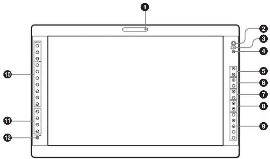
Diagram of a tablet device with labeled ports and connectors, showing numbered labels from 1 to 12.① Tally lamp
You can check the status of the monitor by the color of the tally lamp.
The tally lamp lights in green according to the setting of PARALLEL REMOTE in the REMOTE menu.
② Power indicator
When the power is turned on, the power indicator lights in green.
③ Ⓞ (key inhibit) indicator
Lights in green when KEY INHIBIT in the KEY INHIBIT menu is set to ON.
④ CONTROL button
Press to display the buttons on the front panel. Press again to clear the display.
⑤ CONTRAST buttons
Adjusts the picture contrast.
Press the + button to make the contrast higher or the - button to make it lower.
⑥ PHASE buttons
Press the + button to make the skin tones greenish or the - button to make them purplish.
⑦ CHROMA buttons
Adjusts the color intensity.
Press the + button to increase the color intensity or the - button to decrease it.
⑧ BRIGHT (brightness) buttons
Adjusts the picture brightness.
Press the + button to increase the brightness or the - button to decrease it.
⑨ Menu operation buttons
Displays or sets the on-screen menu. MENU button
Press to display the on-screen menu.
Press again to clear the menu.
+/- buttons
Press to select the items and setting values.
ENTER button
Press to confirm a selected item on the menu.
To display the signal format
When the menu is not displayed and the button is pressed, the recognized signal format is displayed.
RETURN button
When the menu is displayed and the button is pressed, the value of an item is reset to the previous value.
Also, when the fan stops, this button blinks.
To display the names of functions assigned to the function buttons
When the menu is not displayed and the button is pressed, the function selected in FUNCTION BUTTON SETTING of the USER CONFIG menu is displayed on the side of the F1 to F4 button.
⑩ Input select buttons
Press the button to monitor the signal input to each connector.
A-1, A-2, B-1 and B-2 buttons are used when an optional input adaptor has been installed in the option port.
COMPOSITE button: to monitor the signal through the COMPOSITE IN connector
Y/C button: to monitor the signal through the Y/C IN connector
RGB button: to monitor the RGB signal through the connectors for the R/G/B signal input
COMPONENT button: to monitor the component signal through the connectors for Y/PB/PR signal input
A-1 button: to monitor the signal from connector 1 of the input adaptor installed in the option port A or R/G/B signal from BKM-229X/BKM-256DD installed in the option port A
A-2 button: to monitor the signal from connector 2 of the input adaptor installed in the option port A or Y/PB/PR signal from BKM-229X/BKM-256DD installed in the option port A
B-1 button: to monitor the signal from connector 1 of the input adaptor installed in the option port B or R/G/B signal from BKM-229X/BKM-256DD installed in the option port B
B-2 button: to monitor the signal from connector 2 of the input adaptor installed in the option port B or Y/PB/PR signal from BKM-229X/BKM-256DD installed in the option port B
HD15 button: to monitor the signal through the HD15 input connector
DVI button: to monitor the signal through the DVI-D input connector
⑪ Function buttons
You can turn the assigned function on or off.
The factory setting is as follows;
F1 button: EXT SYNC
F2 button: SCAN
F3 button: ASPECT
F4 button: MULTI DISPLAY
You can assign a function from among SCAN, ASPECT, EXT SYNC, BLUE ONLY, MONO, MULTI DISPLAY, DISPLAY LAYOUT, SUB INPUT SELECT, POSITION, FRAME, APA, I/P MODE, MIRROR IMAGE, AUTO SYNC DETECT and FLICKER FREE via FUNCTION BUTTON SETTING in the USER CONFIG menu (see page 73).
For details of the function assigned to the function button, see page 73.
⑫ USER MEM (user memory) button
Press to load the picture settings saved in the USER MEMORY menu (on page 77).
Input Signals and Adjustable/Setting Items
O: Adjustable/can be set
×: Not adjustable/cannot be set
*1 Adjustment of SUB CONTROL is the same.
*2 When a component signal (480/60I or 480/60P) is input and the COMPONENT LEVEL is set to SMPTE, this can be switchable.
*3 When a BKM-227W is installed, the number of the input connector is increased.
*4 When a BKM-229X is installed, the number of the input connector is increased.
*5 When a BKM-220D, BKM-243HSM or BKM-250TGM is installed, the signal can be input.
*6 When a BKM-243HSM or BKM-250TGM is installed, the signal can be input.
*7 Only the interlace signal is input.
*8 The signal can operate with PRESET 2 to 6 (see page 82).
*9 For details on the input signal available for the multi display, see "For the multi display" (page 84).
*10 The signal cannot operate with PRESET 7 and 8 (see page 82).
*11 The signal can only operate with PRESET 1 (see page 82).
*12 The signal can only operate with PRESET 6 (see page 82).
*13 When a BKM-256DD is installed, the number of the input connector is increased.
*14 When a BKM-250TGM is installed, the signal can be input.
*15 Only NORMAL/NATIVE can be selected.
Rear Panel
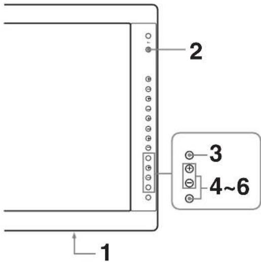
text_image
Technical diagram of a computer rear panel with numbered labels pointing to ports and connectors① ↓/⊥ (Equipotential/Function Earth) terminal
Connects the earth cable.
② COMPOSITE IN connector (BNC)
Input connector for composite signals.
③ Y/C IN connector (4-pin mini-DIN)
Input connector for Y/C signals.
④ G/Y IN connector (BNC)
Input connector for G of RGB signals and component Y (luminance) signals.
⑤ B/P B IN connector (BNC)
Input connector for B of RGB signals and Pb (blue color difference) of component signals.
⑥ R/P R IN connector (BNC)
Input connector for R of RGB signals and PR (red color difference) of component signals.
⑦ EXT SYNC IN (external sync input) connector (BNC)
When this unit operates on an external sync signal, connect the reference signal from a sync generator to this connector.
To use the external sync signal, press the function button that EXT SYNC is assigned (F1 button at the factory setting).
Note
When inputting a video signal with the jitters, etc. the picture may be disturbed. We recommend using the TBC (time base corrector).
⑧ Loop-through output connectors
Outputs the signals input to the input connectors (② to
⑦). Connect to the analog input (composite, Y/C, analog component, analog RGB or external sync) of equipment, according to the input signal.
When a cable is connected to one of these connectors, the 75-ohm termination of the corresponding input is automatically released, and the signal input to the input connector is output.
⑨ Optional input port
An optional input adaptor can be installed according to your system configuration (see page 61).
The left side port is A and the right side port B. Press the A-1, A-2, B-1 or B-2 button to select the signal.
⑩ / (power) switch
The power is turned on or off. The monitor is turned on by pressing side ⊙
⑪ DC 5V/24V IN connector
Connect the DC IN connector of the supplied AC adaptor.
12 PARALLEL REMOTE connector (modular connector, 8-pin)
Forms a parallel switch and controls the monitor externally.
When the unit is shipped from the factory, a connector cover is attached to this connector. Remove it before using the connector.
For removing the connector cover, see page 61.
For details on the pin assignment and factory setting function assigned to each pin, see page 80.
CAUTION
For safety, do not connect the connector for peripheral device wiring that might have excessive voltage to this port. Follow the instructions for this port.
13 SERIAL REMOTE connector (RJ-45)
Connect to the network by using a 10BASE-T/100BASE-TX LAN cable (shielded type, optional). When the unit is shipped from the factory, a connector cover is attached to this connector. Remove it before using the connector.
For removing the connector cover, see page 61.
For details on this connector, refer to the Interface Manual for Programmers (saved in the supplied CD-ROM, Japanese and English only.)
CAUTION
- When you connect the LAN cable of the unit to peripheral device, use a shielded-type cable to prevent malfunction due to radiation noise.
- For safety, do not connect the connector for peripheral device wiring that might have excessive voltage to this port. Follow the instructions for this port.
- The connection speed may be affected by the network system. This unit does not guarantee the communication speed or quality of 10BASE-T/100BASE-TX.
14 SERIAL REMOTE RS-232C connector (D-sub 9-pin, female)
Connect to the RS-232C control connector on external equipment connected to the monitor. The monitor can be operated according to control commands sent from external equipment connected to it.
For details on the pin assignment and factory setting function assigned to each pin, see page 80.
For details on this connector, refer to the Interface Manual for Programmers (saved in the supplied CD-ROM, Japanese and English only.)
15 DVI-D input connector (DVI-D)
Inputs DVI Rev.1.0 applicable digital RGB signal. To view the signals of the SXGA and higher resolution when the DVI input is selected, use the cable within 3 m (118 ^1/8 inches) in length.
16 HD15 input connector (D-sub 15-pin, female)
Inputs an analog RGB video signal (0.7 Vp-p, positive polarity) and sync signal. The Plug & Play function corresponds to DDC2B.
⑰ Screw holes
Holes to be used when attaching an optional stand.
Connecting the AC Power Cord
Connect the supplied AC power cord as illustrated. Two kinds of AC plug holders are supplied with this unit. Use the AC plug holder that fits the AC power cord most securely.
1 Plug the AC power cord into the AC IN socket on the AC adaptor. Then, attach the AC plug holder to the AC power cord.

text_image
AC IN socket AC power cord AC plug holder (Supplied)2 Slide the AC plug holder over the cord until it locks.

natural_image
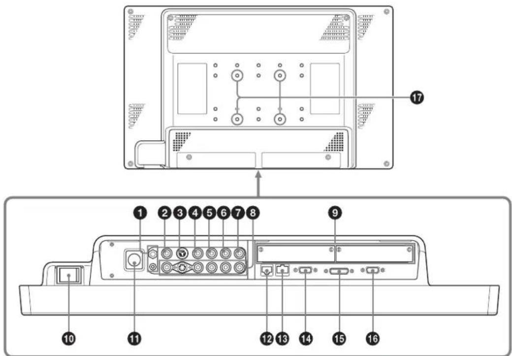
Line drawing of a plug inserted into a socket (no text or symbols)3 Insert the DC IN connector into the DC 5V/24V IN connector on the bottom of this unit until it locks.
natural_image
Technical line drawing of a vehicle rear panel with side door and seat, showing internal components (no text or symbols)To remove the AC power cord
First, pull out the AC plug holder while pressing the lock levers.
Next, pull out the DC IN connector from the DC 5V/24V IN connector while pressing the lock lever.
Installing the Input Adaptor
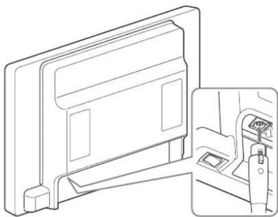
Before installing the input adaptor, disconnect the power cord.
1 Remove the panel of the optional input port.
natural_image
Technical diagram of a mechanical component with multiple slots and a tool, no visible text or symbols2 Insert the input adaptor into the port.
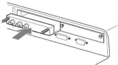
natural_image
Technical line drawing of a mechanical assembly with ports and brackets (no text or symbols)3 Tighten the screws.

natural_image
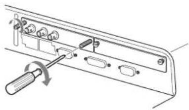
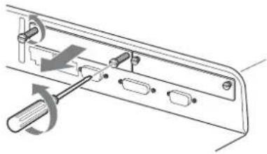
Diagram of a mechanical component with a screwdriver inserted, showing internal parts and a rotation arrow (no text or symbols)Removing the Connector Cover
When the unit is shipped from the factory, a connector cover is attached to the PARALLEL REMOTE connector and the SERIAL REMOTE connector (RJ-45).
To use the connector, remove the connector cover as follows.
Before removing the connector cover, disconnect the power cord.
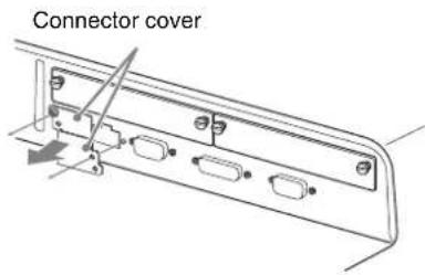
text_image
Connector cover1 Remove the screw of the connector cover.
2 Remove the connector cover.
Save the screw and cover, so that you can reattach the cover if necessary.
Caution
These connectors are designed to allow direct contact with conductive circuits. Weak voltage may be present because of a failure in this unit. To prevent patients from touching these connectors accidentally, attach the connector covers when the connectors are not being used to connect to other devices.
Selecting the Default Settings
When you turn on the unit for the first time after purchasing it, select the area where you intend to use this unit from among the options.
The default setting values for each area

text_image
World map with numbered regions highlighting major geographical areas including Asia, Africa, and parts of Europe.| COLOR TEMP | COMPONENT LEVEL | NTSC SETUP | FLICKER FREE | |
| 1NORTH AMERICA D65 BETA7.5 7.5 OFF | ||||
| 2LATIN AMERICA | ||||
| PAL&PAL-N AREA | ||||
| ARGENTINA D65 SMPTE 0 ON | ||||
| PARAGUAY D65 SMPTE 0 ON | ||||
| URUGUAY D65 SMPTE 0 ON | ||||
| NTSC&PAL-M AREA | ||||
| OTHER AREA D65 BETA7.5 7.5 OFF | ||||
| 3AFRICA AUSTRALASIA EUROPE MIDDLE-EAST | D65 SMPTE 0 ON | |||
| 4ASIA EXCEPT JAPAN | ||||
| NTSC AREA | D65 BETA7.5 7.5 OFF | |||
| PAL AREA | D65 SMPTE 0 ON | |||
| 5JAPAN | D93 | SMPTE | 0 | OFF |

text_image
1 2 3~41 Turn on the unit with the (power) switch on the rear panel.
The SELECT SETTING screen appears.
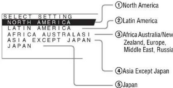
text_image
SELECT SETTING NORTH AMERICA LATIN AMERICA AFRICA AUSTRALASI ASIA EXCEPT JAPAN JAPAN ①North America ②Latin America ③Africa Australia/New Zealand, Europe, Middle East, Russia ④Asia Except Japan ⑤Japan2 Press the CONTROL button.
3 Press the + or - button to select the area where you intend to use the unit and press the ENTER button.
If you select either ①, ③ or ⑤
The confirmation screen is displayed. Confirm the selected area. When the setting is wrong, press the RETURN button to return to the previous screen.

text_image
SELECT THIS AREA? NORTH AMERICA [ENTER]YES [RETURN]NOIf you select either ② or ④
One of the following screens appears. Press the + or - button to narrow the area further and then press the ENTER button.
The confirmation screen is displayed. Confirm the selected area. When the setting is wrong, press the RETURN button to return to the previous screen.
②If LATIN AMERICA is selected:
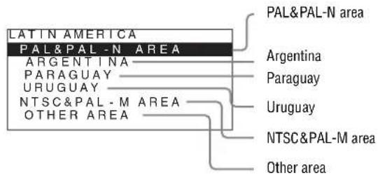
text_image
LATIN AMERICA PAL&PAL-N AREA ARGENTINA PARAGUAY URUGUAY NTSC&PAL-M AREA OTHER AREA PAL&PAL-N area Argentina Paraguay Uruguay NTSC&PAL-M area Other area④If ASIA EXCEPT JAPAN is selected:
Customers who will use this unit in the shaded areas shown in the map below should select NTSC AREA.
Other customers should select PAL AREA.

natural_image
Outline map of East Asia and surrounding regions, highlighting a specific country in the central South Asia Sea (no text or labels)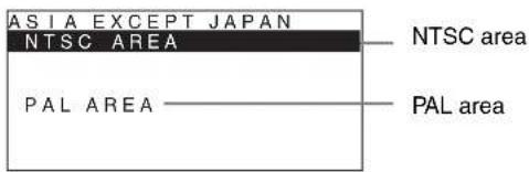
text_image
ASIA EXCEPT JAPAN NTSC AREA PAL AREA NTSC area PAL area4 Press the ENTER button.
The SELECT SETTING screen disappears and the menu item settings suitable for the selected area are applied.
Note
When you have selected the wrong area, set the following items using the menu.
• COLOR TEMP (on page 68)
• COMPONENT LEVEL (on page 70)
• NTSC SETUP (on page 70)
- FLICKER FREE (on page 72)
See “The default setting values for each area” (page 62) on the setting value.
Selecting the Menu Language
You can select one of seven languages (English, French, German, Spanish, Italian, Japanese, Chinese) for displaying the menu and other on-screen displays.
“ENGLISH (English)” is selected in the default setting. The current settings are displayed in place of the ■ marks on the illustrations of the menu screen.
text_image
1 2 3 4~61 Turn on the unit.
2 Press the CONTROL button.
The operation buttons are displayed.
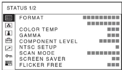
3 Press the MENU button.
The menu appears.
The menu presently selected is shown in yellow.
text_image
STATUS 1/2 FORMAT COLOR TEMP GAMMA COMPONENT LEVEL NTSC SETUP SCAN MODE SCREEN SAVER FLICKER FREE4 Press the + or - button to select SYSTEM SETTING of the USER CONFIG (User Configuration) menu, then press the ENTER button.
The setting items (icons) in the selected menu are displayed in yellow.
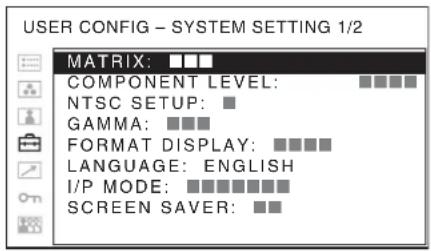
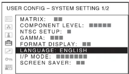
text_image
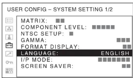
USER CONFIG - SYSTEM SETTING 1/2 MATRIX: ■■■ COMPONENT LEVEL: ■■■■ NTSC SETUP: ■ GAMMA: ■■■ FORMAT DISPLAY: ■■■■ LANGUAGE: ENGLISH I/P MODE: ■■■■■■■ SCREEN SAVER: ■■5 Press the + or - button to select "LANGUAGE," then press the ENTER button.
The selected item is displayed in yellow.
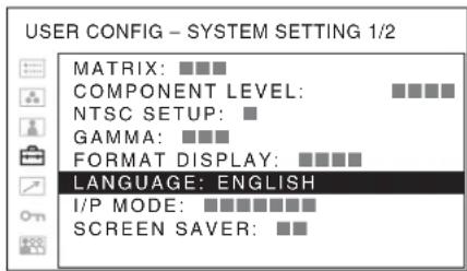
text_image
USER CONFIG - SYSTEM SETTING 1/2 MATRIX: ■■■ COMPONENT LEVEL: ■■■■ NTSC SETUP: ■ GAMMA: ■■■ FORMAT DISPLAY: ■■■■ LANGUAGE: ENGLISH I/P MODE: ■■■■■■■■ SCREEN SAVER: ■■6 Press the + or - button to select a language, then press the ENTER button.
The menu changes to the selected language.
text_image
USER CONFIG - SYSTEM SETTING 1/2 MATRIX: ■■ COMPONENT LEVEL: ■■■■■ NTSC SETUP: ■ GAMMA: ■■■ FORMAT DISPLAY: ■■ LANGUAGE: ENGLISH I/P MODE: ■■■■■■■ SCREEN SAVER: ■■To clear the menu
Press the MENU button.
The menu disappears automatically if a button is not pressed for one minute.
Using the Menu
The unit is equipped with an on-screen menu for making various adjustments and settings such as picture control, input setting, set setting change, etc. You can also change the menu language displayed in the on-screen menu.
To change the menu language, see “Selecting the Menu Language” on page 63.
The current settings are displayed in place of the ■ marks on the illustrations of the menu screen.
text_image
1 2 3~5 RETURN button1 Press the CONTROL button.
The operation buttons are displayed.
2 Press the MENU button.
The menu appears.
The menu presently selected is shown as a yellow button.
text_image
STATUS 1/2 FORMAT COLOR TEMP GAMMA COMPONENT LEVEL NTSC SETUP SCAN MODE SCREEN SAVER FLICKER FREE3 Use the + or - button to select a menu, then press the ENTER button.
The menu icon presently selected is shown in yellow and setting items are displayed.
text_image
USER CONFIG - SYSTEM SETTING 1/2 MATRIX: ■■ COMPONENT LEVEL: ■■■■■ NTSC SETUP: ■ GAMMA: ■■■ FORMAT DISPLAY: ■■ LANGUAGE: ENGLISH I/P MODE: ■■■■■■■ SCREEN SAVER: ■■4 Select an item.
Use the + or - button to select the item, then press the ENTER button.
The item to be changed is displayed in yellow. If the menu consists of multiple pages, press + or - button to go to the desired menu page.
5 Make the setting or adjustment on an item.
When changing the adjustment level:
To increase the number, press the + button.
To decrease the number, press the - button.
Press the ENTER button to confirm the number, then restore the original screen.
When changing the setting:
Press the + or - button to change the setting.
Press the ENTER button to confirm the setting.
When returning the adjustment or setting to the previous value:
Press the RETURN button before pressing the ENTER button.
Notes
- An item displayed in black cannot be accessed. You can access the item if it is displayed in white.
- If the key inhibit has been turned on, all items are displayed in black. To change any of the items, turn the key inhibit to OFF first.
For details on the key inhibit, see page 76.
To return the display to the previous screen
Press the RETURN button.
To clear the menu
Press the MENU button.
The menu disappears automatically if a button is not pressed for one minute.
About the memory of the settings
The settings are automatically stored in the monitor memory.
Loading USER MEMORY
You can load the picture settings saved in the USER MEMORY menu (on page 77).
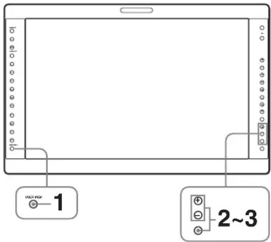
text_image
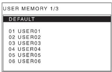
VCH FDP 1 2~31 Press the USER MEM button.
The USER MEMORY menu appears.
text_image
USER MEMORY 1/3 DEFAULT 01 USER01 02 USER02 03 USER03 04 USER04 05 USER05 06 USER062 Select the memory number.
+ or - button: to select the memory number
3 Press the ENTER button.
After loading the picture settings from the selected memory, the menu disappears.
To stop selecting the memory
Press the USER MEM button.
The USER MEMORY menu disappears.
To reset the settings
Select "DEFAULT," then press the ENTER button.
Adjustment Using the Menus
Items
The screen menu of this monitor consists of the following items.
STATUS (the items indicate the current settings.)
For the video input
FORMAT
COLOR TEMP
GAMMA
COMPONENT LEVEL
NTSC SETUP
SCAN MODE
SCREEN SAVER
FLICKER FREE
Model name and serial number
OPTION A and serial number
OPTION B and serial number
For the DVI/HD15 input
FORMAT
fH
fV
COLOR TEMP
GAMMA
SCREEN SAVER
FLICKER FREE
Model name and serial number
OPTION A and serial number
OPTION B and serial number
COLOR TEMP/SPACE
COLOR TEMP
MANUAL ADJUSTMENT
COLOR SPACE
USER CONTROL
For the video input
AUTO CHROMA/PHASE
SUB CONTROL
PICTURE CONTROL
INPUT SETTING
For the DVI/HD15 input
SUB CONTROL
PICTURE CONTROL

USER CONFIG
SYSTEM SETTING
MATRIX
COMPONENT LEVEL
NTSC SETUP
GAMMA
FORMAT DISPLAY
LANGUAGE
I/P MODE
SCREEN SAVER
SD PIXEL MAPPING
SPLASH LOGO
FLICKER FREE
MULTI DISPLAY SETTING
MULTI DISPLAY ENABLE
DISPLAY LAYOUT
SUB INPUT SELECT
POSITION
FRAME
SUB PICTURE SIZE
FUNCTION BUTTON SETTING
F1 BUTTON
F2 BUTTON
F3 BUTTON
F4 BUTTON
COMPUTER DETECT
DVI
HD15
OPTION DVI SETTING ^*1
EXT 5V(DVI-IN)
EXT 5V(DVI-OUT)
EDID UPDATE
EDID STATUS
*1 Displayed only when a BKM-256DD is installed.

REMOTE
PARALLEL REMOTE
SERIAL REMOTE
MONITOR
CONNECTION

KEY INHIBIT
KEY INHIBIT

USER MEMORY
01 to 20
Adjusting and Changing the Settings

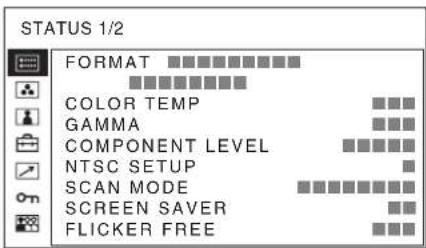
STATUS menu
The STATUS menu is used to display the current status of the unit. The following items are displayed:
For the video input
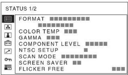
text_image
STATUS 1/2 FORMAT COLOR TEMP COMPONENT LEVEL NTSC SETUP SCAN MODE SCREEN SAVER FLICKER FREE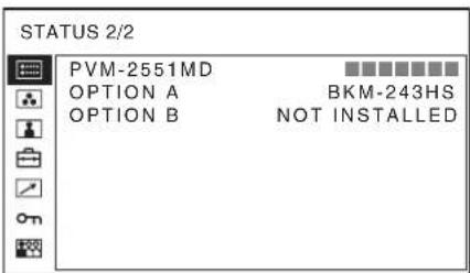
text_image
STATUS 2/2 PVM-2551MD OPTION A OPTION B BKM-243HS NOT INSTALLED- Signal format
• Color temperature - Gamma
- Component level
- NTSC setup
- Scan mode
- Screen saver
- Flicker free
- Model name and serial number
• OPTION A and serial number
• OPTION B and serial number
For the DVI/HD15 input
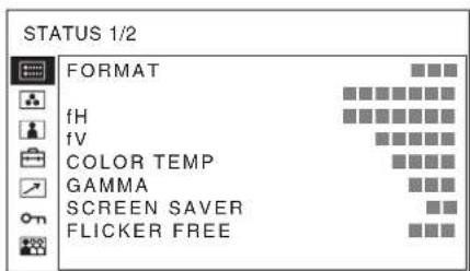
text_image
STATUS 1/2 FORMAT fH fV COLOR TEMP GAMMA SCREEN SAVER FLICKER FREE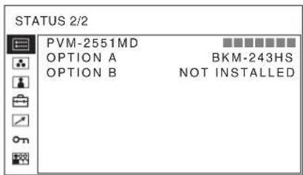
text_image
STATUS 2/2 PVM-2551MD OPTION A BKM-243HS OPTION B NOT INSTALLED- Signal format
• fH
• fV
• Color temperature - Gamma
-
Screen saver
-
Flicker free
- Model name and serial number
• OPTION A and serial number
• OPTION B and serial number
COLOR TEMP/SPACE menu
The COLOR TEMP/SPACE menu is used for adjusting the picture white balance or color space.
You need to use the measurement instrument to adjust the white balance.
Recommended: Konica Minolta color analyzer CA-210
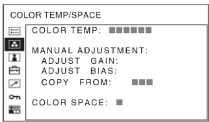
text_image
COLOR TEMP/SPACE COLOR TEMP: ■■■■■■ MANUAL ADJUSTMENT: ADJUST GAIN: ADJUST BIAS: COPY FROM: ■■■ COLOR SPACE: ■Submenu Setting
| COLOR TEMP Selects the color temperature fromamong “D93,” “D65,” “D56,”“USER1,” “USER2,” “USER3,”“USER4” and “USER5.” | |
| MANUALADJUSTMENT | If you set the COLOR TEMP to“USER1,” “USER2,” “USER3,”“USER4” or “USER5” setting, theitem displayed is changed fromblack to white, which means youcan adjust the color temperature.The set values are memorized.• ADJUST GAIN: Adjusts thecolor balance (GAIN).• ADJUST BIAS: Adjusts thecolor balance (BIAS).• COPY FROM: If you select“D93,” “D65” or “D56,” thewhite balance data for theselected color temperaturewill be copied in the“USER1,” “USER2,”“USER3,” “USER4” or“USER5” setting. |
| COLOR SPACE Selects the color space from amongITU-709, EBU, SMPTE-C andOFF. OFF sets the color space tothe original color reproduction ofthe panel. | |
USER CONTROL menu
The USER CONTROL menu is used for adjusting the picture.
Items that cannot be adjusted depending on the input signal are displayed in black.
For details of input signals and adjustable/setting items, see page 57.
For the video input
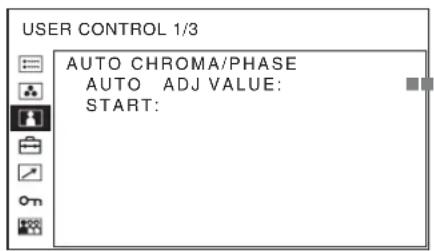
text_image
USER CONTROL 1/3 AUTO CHROMA/PHASE AUTO ADJ VALUE: START: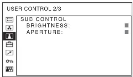
text_image
USER CONTROL 2/3 SUB CONTROL BRIGHTNESS: APERTURE: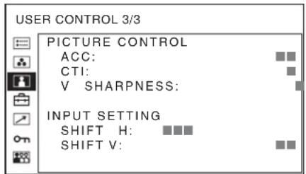
text_image
USER CONTROL 3/3 PICTURE CONTROL ACC: CTI: V SHARPNESS: INPUT SETTING SHIFT H: SHIFT V:Submenu Setting
| AUTO CHROMA/PHASE | Adjusts color intensity (CHROMA) and tones (PHASE).• AUTO ADJ VALUE: Selects ON or OFF of the auto adjustment. When you set to OFF, this parameter is reset to the factory setting. When you set to ON, the automatically adjusted value is enabled.• START: The auto adjustment starts when you display the color bar signals (Full/ SMPTE/EIA) on the screen and press the ENTER button. After adjusting the color intensity, press the MENU button to clear the adjustment screen. After the adjustment is done correctly, the AUTO ADJ VALUE is automatically set to ON. |
Submenu Setting
SUB CONTROL Adjusts finely the adjustment range of the button on the front panel for BRIGHTNESS.
• BRIGHTNESS: Adjusts the picture brightness.
- APERTURE: Adjusts the picture sharpness.
The higher the setting, the sharper the picture. The lower the setting, the softer the picture.
PICTURE CONTROL Adjusts the picture.
- ACC (Auto Color Control): Sets ACC circuit on or off. To check the fine adjustment, select OFF. Normally select ON.
- CTI (Chroma Transient Improvement): When a low color resolution signal is input, a crisp image can be displayed. When the setting is higher, the picture becomes even more crisp.
• V SHARPNESS: A crisp image can be displayed. When the setting is higher, the picture becomes even more crisp.
INPUT SETTING • SHIFT H: Adjusts the position of the picture. As the setting increases, the picture moves to the right, and as the setting decreases, the picture moves to the left. • SHIFT V: Adjusts the position of the picture. As the setting increases, the picture moves up, and as the setting decreases, the picture moves down.
For the DVI/HD15 input
* The 1/3 menu cannot be adjusted.
text_image
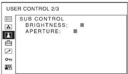
USER CONTROL 2/3 SUB CONTROL BRIGHTNESS: APERTURE: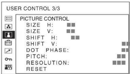
text_image
USER CONTROL 3/3 PICTURE CONTROL SIZE H: ■■ SIZE V: ■■ SHIFT H: ■■ SHIFT V: ■■ DOT PHASE: PITCH: RESOLUTION: RESETSubmenu Setting
SUB CONTROL Adjusts finely the adjustment range of the button on the front panel for BRIGHTNESS. • BRIGHTNESS: Adjusts the picture brightness. • APERTURE: Adjusts the picture sharpness. The higher the setting, the sharper the picture. The lower the setting, the softer the picture.
Submenu Setting
PICTURE CONTROL Adjusts to monitor the picture more clearly.
- SIZE H: Adjusts the horizontal size of the picture. The higher the setting, the larger the horizontal size of the picture. The lower the setting, the smaller the horizontal size of the picture.
- SIZE V: Adjusts the vertical size of the picture. The higher the setting, the larger the vertical size of the picture. The lower the setting, the smaller the vertical size of the picture.
- SHIFT H: Adjusts the position of the picture. As the setting increases, the picture moves to the right, and as the setting decreases, the picture moves to the left.
- SHIFT V: Adjusts the position of the picture. As the setting increases, the picture moves up, and as the setting decreases, the picture moves down.
- D O T P H A S E : Adjusts the dot phase. Adjust the picture further for a finer picture after APA (page 74) is adjusted.
- PITCH: Adjusts the horizontal size of the picture with the left side of the picture fixed. The higher the setting, the larger the width of the picture. The lower the setting, the narrower the width of the picture.
- RESOLUTION: Sets when the computer signal is input and it is difficult to understand the signal type such as XGA/60 or WXGA/60
- XGA: Displayed as XGA signal.
- WXGA: Displayed as WXGA signal.
- RESET: Resets the value of SIZE H, SIZE V, SHIFT H, SHIFT V, DOT PHASE and PITCH to the factory preset value.

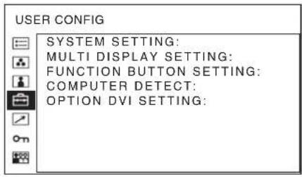
USER CONFIG menu
The USER CONFIG menu is used for setting the system, multi display, function button, computer detect and option DVI.
text_image
USER CONFIG SYSTEM SETTING: MULTI DISPLAY SETTING: FUNCTION BUTTON SETTING: COMPUTER DETECT: OPTION DVI SETTING:SYSTEM SETTING
text_image
USER CONFIG - SYSTEM SETTING 1/2 MATRIX: □□□ COMPONENT LEVEL: □□□□□□ NTSC SETUP: ■ GAMMA: □□□ FORMAT DISPLAY: ■ LANGUAGE: ENGLISH I/P MODE: □□□□□□□□ SCREEN SAVER: ■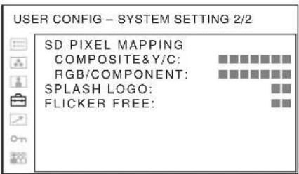
text_image
USER CONFIG - SYSTEM SETTING 2/2 SD PIXEL MAPPING COMPOSITE&Y/C: RGB/COMPONENT: SPLASH LOGO: FLICKER FREE:Submenu Setting
| MATRIX Applied to 480/60I or 480/60P signal. Select 601 or 709. |
| COMPONENT LEVEL Selects the component level from among three modes.SMPTE: for 100/0/100/0 signalBETA0: for 100/0/75/0 signalBETA7.5: for 100/7.5/75/7.5 signal |
| NTSC SETUP Selects the NTSC setup level from two modes.The 7.5 setup level is used mainly in North America. The 0 setup level is used mainly in Japan. |
Submenu Setting
| GAMMA Selects the appropriate gamma mode from the five settings (“1.8,” “2.0,” “2.2,” “2.4,” “2.6,” “DICOM”*). When “2.2” is selected, the setting is roughly same as the gamma mode of the CRT.* “DICOM” is selectable when COLOR SPACE is set to other than ITU-709. |
FORMAT DISPLAY Selects the display mode of the signal format and scan mode
- AUTO: The format is displayed for about 10 seconds when the input of the signal starts.
- OFF: The display is hidden.
LANGUAGE Selects the menu or message language from among seven languages.
• ENGLISH: English
• FRANÇAIS: French
• DEUTSCH: German
- ESPAÑOL: Spanish
• ITALIANO: Italian
• :日本語csc
•:Chinese
Submenu Setting
| I/P MODE (picture delay minimum) | Selects to set the delay by the picture processing to the minimum level when the interlace signal is input. |
- INTER-FIELD ^31 : Mode for giving precedence to the picture quality. Performs interpolation depending on the movement of the images between the fields. It takes longer than “FIELD MERGE” or “LINE DOUBLER” for processing the picture. “INTER-FIELD” is the factory setting.
- FIELD MERGE *2: The processing time is shorter. Combines the lines in the odd fields and even fields alternately regardless of the movement of images. Suitable for viewing still images.
• LINE DOUBLER: The processing time is shorter. Performs interpolation by repeating each line in the data receiving sequence regardless of the field. As the line flicker is displayed in this mode, it is available for checking the line flicker of the telop work and so on.
*1 When MULTI DISPLAY ENABLE is set to ON, INTERFIELD cannot be selected.
*2 When DISPLAY LAYOUT is set to SIDE BY SIDE, FIELD MERGE cannot be selected.
SCREEN SAVER Sets the screen saver function on or off.
- ON: If a still image is displayed for more than 10 minutes, the brightness of the screen is automatically decreased to reduce burn-in. The screen returns to normal brightness when you input an image to the unit or operate the buttons on the front panel of the unit. While the screen saver is activated, the tally lamp lights in amber.
- OFF: The screen saver function is deactivated. This is the factory setting.
Submenu Setting
| SD PIXEL MAPPING Selects SD picture size (pixels) according to input signal format. |
- COMPOSITE&Y/C: Set to monitor the signal input through the COMPOSITE IN connector or Y/C IN connector.
- RGB/COMPONENT: Set to monitor the signal input through the R/G/B IN connector or Y/P_B/P_R IN connector.
When picture signals in the size of 720 × 576 (50i) (or 720 × 487 (60i)) are input
Select 720 × 576 (or 720 × 487). This is the default setting.
When 702 × 576 (or 712 × 483 ) is selected, all sides of the input picture are cut off by several pixels.
When picture signals in the size of 702 × 576 (50i) (or 712 × 483 (60i)) or equivalent are input
Select 702 × 576 (or 712 × 483 ).
When 720 × 576 (or 720 × 487 ) is selected, a black border (of several pixels wide) appears around the input picture.
SPLASH LOGO Sets the splash logo display mode on or off. To display the splash logo, you need to write the splash logo data. For details, consult your Sony dealer.
FLICKER FREE Set this to ON to enable view images without flicker. The ON setting will eliminate flicker, but quick-moving images may exhibit contours or an afterimage. For details, see “About the function assigned to the function button” (page 74).
MULTI DISPLAY SETTING
USER CONFIG - MULTI DISPLAY SETTING
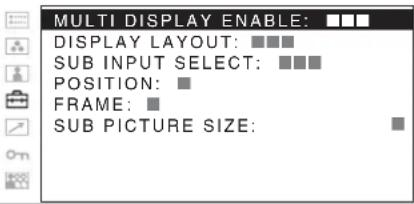
text_image
MULTI DISPLAY ENABLE: DISPLAY LAYOUT: ■■■ SUB INPUT SELECT: ■■■ POSITION: ■ FRAME: ■ SUB PICTURE SIZE: ■| Submenu | Setting |
| MULTI DISPLAY ENABLE | Selects ON to display the multi display and OFF not to display. |
Notes
- When the frame frequency of the main display is different from that of the sub display, the picture may be disturbed.
When no signal is input to the main display, the picture may not be displayed correctly.
- When you set SUB INPUT SELECT to OFF, MULTI DISPLAY ENABLE is set to OFF automatically.
- When MULTI DISPLAY ENABLE is set to ON, APA (page 74) is not available.
DISPLAY LAYOUT
- POP: The sub display is put by the side of the main display. The scan mode can only be selected in the main display.
- PIP: The sub display appears in an inset window of the main display (for 16:9 display only).
- SIDE BY SIDE: The main display is put in the left side of the display and the sub display is put in the right side of the display. Either NORMAL or FULL can be selected for the scan mode in the main and sub display. The scan mode of the main and sub display will change at the same time. You cannot set a different scan mode for each display.
To switch the scan mode, press the function button assigned to change the scan mode. See “FUNCTION BUTTON SETTING” (page 73) and “About the function assigned to the function button” (page 73).
Note
When DISPLAY LAYOUT is set to SIDE BY SIDE, CTI (page 69) is not available.
| Submenu Setting | |
| SUB INPUT SELECT | Sets the input signal of the sub display.You can select from among COMPOSITE, Y/C, RGB, COMPONENT, HD15, DVI, OPTION A-1, OPTION A-2, OPTION B-1, OPTION B-2, VIDEO WAVE and OFF. |
| NotesThe multi display with COMPOSITE and Y/C, RGB and COMPONENT, HD15 and DVI, OPTION A-1 and OPTION A-2, and OPTION B-1 and OPTION B-2 is not displayed.When you set SUB INPUT SELECT to OFF, MULTI DISPLAY ENABLE is set to OFF.The input signal formats available for HD15 and DVI are limited. See “For the multi display” (page 84). | |
| POSITION Sets the position of the sub display.When POP is selected:1: Top2: Center3: BottomWhen PIP is selected:1: Bottom left2: Bottom right3: Top right4: Top left | |
| FRAME Sets the position of the main displaywhen POP is selected in DISPLAY LAYOUT.RIGHT: The main display is put by the right side of the sub display.LEFT: The main display is put by the left side of the sub display. | |
| SUB PICTURE SIZE | Sets the sub display size when PIP is selected in DISPLAY LAYOUT.1: Small2: Large |
FUNCTION BUTTON SETTING
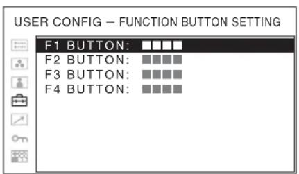
text_image
USER CONFIG - FUNCTION BUTTON SETTING F1 BUTTON: ■■■■ F2 BUTTON: ■■■■ F3 BUTTON: ■■■■ F4 BUTTON: ■■■■| Submenu Setting | |
| F1 BUTTON to F4 BUTTON | Assigns the function to the function buttons of the front panel and turns the function on or off.You can assign the function from among SCAN, ASPECT, EXT SYNC, BLUE ONLY, MONO, MULTI DISPLAY, DISPLAY LAYOUT, SUB INPUT SELECT, POSITION, FRAME, APA, I/P MODE, MIRROR IMAGE, AUTO SYNC DETECT and FLICKER FREE.Factory setting• F1 button: EXT SYNC• F2 button: SCAN• F3 button: ASPECT• F4 button: MULTI DISPLAY |
About the function assigned to the function button
SCAN (Scan mode)
Press to change the scan size of the picture. Press to switch between NATIVE, NORMAL scan (0% scan), OVER scan (20% over scan), FULL and ZOOM (see "Scan mode image" on page 74). NATIVE is effective when a 720p signal and a computer (DVI/HD15) signal are input. FULL is only available when DISPLAY LAYOUT is set to SIDE BY SIDE in the multi display. ZOOM is effective only when 1280 × 1024 or 1440 × 900 signals from DVI are input.
ASPECT
Press to set the aspect ratio of the picture, 4:3 or 16:9.
AUTO SYNC DETECT
Press the assigned button to detect external sync signals and internal sync signals automatically.
The unit synchronizes with external sync signals when they are detected. When external sync signals are not detected, the unit synchronizes with internal sync signals.
AUTO SYNC DETECT works when the component/RGB signals are input.
AUTO SYNC DETECT does not work when signal is input from BKM-229X.
EXT SYNC (external sync)
Press to operate the unit on an external sync signal through the EXT SYNC IN connector. EXT SYNC works when the component/RGB signals are input. If AUTO SYNC DETECT is on, this function is not available.
MULTI DISPLAY
Press the assigned button to display the multi display. Set the multi display setting in the MULTI DISPLAY SETTING menu (see page 72).
DISPLAY LAYOUT
Press the button to set DISPLAY LAYOUT when the multi display is on. The mode switches in the sequence POP → PIP → SIDE BY SIDE with every press of the button (see “DISPLAY LAYOUT” on page 72).
SUB INPUT SELECT
Press the button to set the sub display input signal types when the multi display is on. The mode switches in the sequence COMPOSITE → Y/C → RGB → COMPONENT → HD15 → DVI → OPTION A-1 → OPTION A-2 → OPTION B-1 → OPTION B-2 → VIDEO WAVE with every press of the button (see “SUB INPUT SELECT” on page 73).
POSITION
Press the button to set the sub display position when the PIP or POP multi display is on. The mode switches in the sequence when POP is selected: 1 (Top) → 2 (Center) → 3 (Bottom), when PIP is selected: 1 (Bottom left) → 2 (Bottom right) → 3 (Top right) → 4 (Top left) with every press of the button.
FRAME
Press the button to set the main display position when the POP multi display is on. The mode switches in the sequence RIGHT → LEFT with every press of the button.
SUB PICTURE SIZE
Press the button to set the size of the sub display when the PIP multi display is on. The mode switches in the sequence 1 (Small) → 2 (Large) with every press of the button.
I/P MODE
Press the assigned button to set the delay by the picture processing to the minimum level when interlace signal is input. The mode switches in the sequence INTERFIELD → FIELD MERGE → LINE DOUBLER with every press of the button (see "I/P MODE" on page 71).
MIRROR IMAGE
Press the assigned button to flip and display the video signal horizontally. This function is not available for the PRESET 1 signal and the multi display.

text_image
F → AMONO
Press the assigned button to display a monochrome picture. When the buttons is pressed again, the monitor switches automatically to color mode.
APA (Auto Pixel Alignment)
Press to adjust the picture automatically to maximum clarity for the signal input to the HD15 input connector. For finer according to the input signal, see “DOT PHASE” on page 70.
When the menu screen or the multi display is displayed, APA does not function.
Note
If the APA operation does not finish correctly depending on the input signal, adjust DOT PHASE (page 70).
BLUE ONLY
Press the assigned button to eliminate the red and green signals. Only blue signal is displayed as an apparent monochrome picture on the screen. This facilitates “chroma” and “phase” adjustments and observation of signal noise.
FLICKER FREE
Press the button to change the FLICKER FREE setting.
An OLED panel can provide superior video responsiveness and scan driving, reproducing images with little contouring or afterimaging. However, scan driving can cause flicker when input signals have a low vertical frequency (24P/PsF, 50I, etc.). Set FLICKER FREE to ON to greatly reduce this phenomenon.
With this mode set to ON, quick-moving images may exhibit contours or an afterimage.
Scan mode image
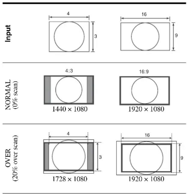
text_image
Input 4 3 16 9 NORMAL (0% scan) 4:3 1440 × 1080 16:9 1920 × 1080 OVER (20% over scan) 4 3 16 9 1728 × 1080 1920 × 1080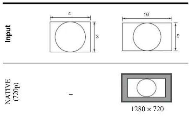
text_image
Input 4 3 16 9 NATIVE (720p) - 1280 × 720COMPUTER DETECT
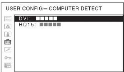
text_image
USER CONFIG—COMPUTER DETECT DVI: HD15:Submenu Setting
| COMPUTER DETECT | The appropriate preset memory is set for the signal from DVI and HD15 input connector. Select “PRESET1” for the standard computer signal. Select “PRESET2” to “PRESET8” when the computer signal is not standard (on page 82). The preset memory is set for each input connector of DVI and HD15. |
Note
"PRESET7" and "PRESET8" will only be displayed when "DVI" is selected.
OPTION DVI SETTING
* This settings are displayed only when a BKM-256DD is installed.
text_image
USER CONFIG - OPTION DVI SETTING OPTION DVI SETTING EXT 5V(DVI-IN): □□ EXT 5V(DVI-OUT): □□ EDID UPDATE: □□□□□□ EDID STATUS: MODEL SER.Submenu Setting
| EXT 5V(DVI-IN) Selects ON to output external 5 Vpower from the DVI input connectors and OFF not to output. |
| EXT 5V(DVI-OUT) Selects ON to output external 5 Vpower from the DVI output connectors and OFF not to output. |
| EDID UPDATE Downloads the EDID informationfrom the main unit (the monitor) to the BKM-256DD. Select “START,” and then press the ENTER button to start downloading the EDID information automatically. During download, “EDID UPDATING...” is displayed and the CONTROL button cannot be operated. When download finishes correctly, “COMPLETE!” is displayed. When a fault occurs, “ERROR” is displayed. Press the RETURN button to display the on-screen menu. |
| EDID STATUS The information downloaded to the BKM-256DD from the EDID of the main unit (the monitor) is displayed.MODEL: Model name of the monitorSER.: Serial number of the monitor |
REMOTE menu
text_image
REMOTE PARALLEL REMOTE: SERIAL REMOTE: MONITOR: CONNECTION:Submenu Setting
PARALLEL REMOTE Selects the PARALLEL REMOTE
connector pins for which you want to change the function.
You can assign various functions to pins 1 to 4 and pins 6 to 8. The following lists the functions you can assign to the pins.
- --- (“---”): No function is assigned.)
• C O M P O S I T E
• Y/C
- RGB
- COMPONENT
• DVI
• HD15
• OPTION A-1
• OPTION A-2
• OPTION B-1
• OPTION B-2
• OVERSCAN
• F U L L
• NORMAL
• ZOOM
• NATIVE
4:3
• 1 6 : 9
• T A L L Y G
- EXT SYNC
• AUTO SYNC DETECT
- BLUE ONLY
• MONO
• MIRROR IMAGE
- FLICKER FREE
Note
If you use the PARALLEL
REMOTE function, you need to connect cables. For more details, see page 80.
SERIAL REMOTE Selects the mode to be used.
- OFF: SERIAL REMOTE does not function.
- ETHERNET: The monitor is controlled by the command of Ethernet.
- RS-232C: The monitor is controlled by the command of RS-232C.
Submenu Setting
MONITOR Set the monitor setting.
MONITOR ID: Sets the ID of the monitor.
GROUP ID: Sets the group ID of the monitor.
IP ADDRESS: Sets the IP address.
SUBNET MASK: Sets the subnet mask.
(255.255.255.000)
DEFAULT GATEWAY:
Sets the default gateway on or off.
ADDRESS: Sets the default gateway.
CANCEL: Selects to cancel the setting.
CONFIRM: Selects to save the setting.
CONNECTION Sets the connection of the monitor and the controller.
PEER TO PEER: for one to one connection
LAN: for connection via a network
on KEY INHIBIT menu
text_image
KEY INHIBIT KEY INHIBIT: ■■You can lock the setting so that they cannot be changed by an unauthorized user.
Select OFF or ON.
If you set to ON, all items are displayed in black, indicating the items are locked.

USER MEMORY menu
text_image
USER MEMORY 1/3 01 USER01 02 USER02 03 USER03 04 USER04 05 USER05 06 USER06 07 USER07 08 USER08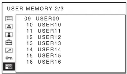
text_image
USER MEMORY 2/3 09 USER09 10 USER10 11 USER11 12 USER12 13 USER13 14 USER14 15 USER15 16 USER16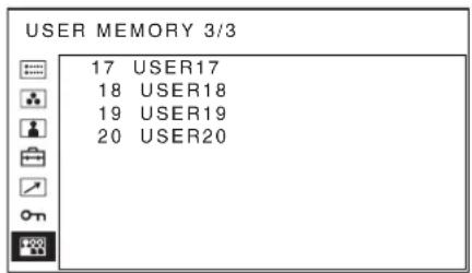
text_image
USER MEMORY 3/3 17 USER17 18 USER18 19 USER19 20 USER20Submenu Setting
01 to 20 You can save the setting of the following
functions.
- CONTRAST
• BRIGHTNESS
- CHROMA
- PHASE
• S C A N
• A S P E C T
COLOR TEMP/SPACE menu
- COLOR TEMP
- ADJUST GAIN
- ADJUST BIAS
• COLOR SPACE
USER CONTROL menu
• BRIGHTNESS
• A P E R T U R E
SYSTEM SETTING menu
• GAMMA
- I/P MODE
COMPUTER DETECT menu
• DVI
• HD15
Saving the user memory
You can save the 20 picture settings with the name. To load the picture in the saved setting, see “Loading USER MEMORY” on page 66.
To save the picture setting
1 Press the + or - button to select the memory number in the USER MEMORY menu, then press the ENTER button.
The USER MEMORY setting menu appears.
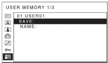
text_image
USER MEMORY 1/3 01 USER01 SAVE: NAME:2 Select "SAVE," then press the ENTER button.
The menu for confirming the memory appears.

text_image
SAVE TO USER MEMORY 01 ? [ENTER] YES [RETURN] NO3 Press the ENTER button.
The current picture settings are saved and the USER MEMORY setting menu appears.
To close the menu without saving the setting
Press the RETURN button.
The USER MEMORY setting menu appears.
To change the name
1 Press the + or - button to select the memory number in the USER MEMORY menu, then press the ENTER button.
The USER MEMORY setting menu appears.
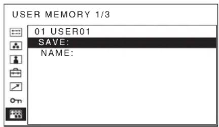
text_image
USER MEMORY 1/3 01 USER01 SAVE: NAME:2 Press the – button to select “NAME,” then press the ENTER button.
The menu for setting the user name appears.
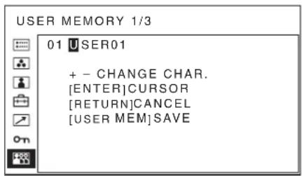
text_image
USER MEMORY 1/3 01 USER01 + - CHANGE CHAR. [ENTER]CURSOR [RETURN]CANCEL [USER MEM]SAVE3 Change the user name.
- Press the ENTER button to move the cursor to the character position to be changed.
- Press the + or – button to change the character. Usable characters: “A to Z,” “0 to 9,” “.”, “/”, “,”, “_”, “-”, “(space)” Usable number of characters: Maximum 18 characters.
- Enter a space to clear the character.
- When the ENTER button is pressed after changing the character, the character is confirmed and the cursor moves to the following character.
4 Press the USER MEM button.
The settings are saved and the USER MEMORY setting menu appears.
To close the menu without saving the setting
Press the RETURN button.
The USER MEMORY setting menu appears.
Troubleshooting
This section may help you isolate the cause of a problem and as a result, eliminate the need to contact technical support.
- The display is colored in green or purple → Select the correct input by pressing RGB or COMPONENT button.
- The unit cannot be operated → The key protection function works. Set the KEY INHIBIT setting to OFF in the KEY INHIBIT menu.
- The black bars appear at the upper and lower positions of the display When the signal aspect ratio is different from that of the panel, the black bars appear. This is not a failure of the unit.
Specifications
Picture performance
Panel OLED panel
Picture size (diagonal)
623.4 mm (24 ^5 /8 inches)
Effective Picture size (H × V)
543.4 × 305.6 mm
(21^1 / 2× 12^1 / 8 inches)
Resolution (H × V)
1920 × 1080 pixels (Full HD)
Aspect 16:9
Pixel efficiency 99.99%
Panel drive RGB 10-bit
Viewing angle (panel specification)
89^ / 89^ / 89^ / 89^ (typical) (up/down/
left/right, contrast > 10:1)
Normal scan 0% scan
Over scan 20% over scan
Warm-up time Approx. 30 minutes
To provide stable picture quality, turn on the power of the monitor and leave it in this state for more than 30 minutes.
Input
Composite input (NTSC/PAL) connector
BNC type (×1)
1 Vp-p ± 3 dB sync negative
Y/C input connector
Mini-DIN 4-pin (×1)
Y: 1 Vp-p ± 3 dB sync negative
C: 0.286 Vp-p ± 3 dB (NTSC burst signal level)
0.3 Vp-p ± 3 dB (PAL burst signal
level)
RGB/component input connectors
BNC type (×3)
RGB: 0.7 Vp-p ± 3 dB (Sync On
Green, 0.3 Vp-p sync negative)
Component: 0.7 Vp-p ± 3 dB (75%
chrominance standard color bar signal)
External synchronized input connector
BNC type (×1)
0.3 Vp-p to 4.0 Vp-p ± bipolarity
ternary or negative polarity binary
HD15 input connector
D-sub 15-pin (×1)
R/G/B: 0.7 Vp-p, sync positive (Sync
On Green, 0.3 Vp-p sync negative)
Sync: TTL level (polarity free, H/V separate sync)
Plug & Play function: corresponds to DDC2B
DVI-D input connector
DVI-D (×1)
TMDS single link
Parallel remote
Modular connector 8-pin (×1)
Serial remote (LAN)
D-sub 9-pin (RS-232C) (×1)
RJ-45 modular connector (×1)
(Ethernet, 10BASE-T/100BASE-TX)
Optional input port
2 ports
Signal format:
H: 15 kHz to 45 kHz
V: 48 Hz to 60 Hz
DC IN connector
XLR-type 4-pin (male) (× 1) , DC 5V/
24V (output impedance 0.05 ohms
or less)
Output
Composite output connector
BNC type (×1)
Loop-through, with 75 ohms automatic terminal function
Y/C output connector
Mini-DIN 4-pin (×1)
Loop-through, with 75 ohms automatic terminal function
RGB/component output connectors
BNC type (×3)
Loop-through, with 75 ohms automatic terminal function
External synchronized output connector
BNC type (×1)
Loop-through, with 75 ohms automatic terminal function
General
Power OLED monitor (PVM-2551MD/
2551NB)
DC IN: 24 V 5.0 A 5 V 0.030 A
(Supplied from AC adaptor)
AC Adaptor (Sony, AC-110MD)
AC IN: 100 V-240 V, 50/60 Hz, 1.53 A-0.58 A
DC OUT: 24 V 5.0 A 5 V 0.060 A
Power consumption
Approx. 135 W (max.)
Approx. 80 W (average power
consumption in the default status)
Operating conditions
Temperature
0^ to 35^ (32°F to 95°F)
Recommended temperature
20^ to 30^ (68°F to 86°F)
Humidity 30% to 85% (no condensation)
Pressure 700 hPa to 1060 hPa
Storage and transport temperature
-20^ to +60^ (-4^ to +140^)
Storage and transport humidity
0% to 90% (no condensation allowed)
Storage and transport pressure
700 hPa to 1060 hPa
Accessories supplied
AC adaptor (AC-110MD) (1)
AC power cord (1)
AC plug holder (2)
Instructions for Use (1)
CD-ROM (1)
Using the CD-ROM Manual (1)
Quick Reference (1)
When you First Use the Monitor (1)
Service Contact List (1)
European Representative (1)
Optional accessories
SDI 4:2:2 input adaptor BKM-220D
HD/D1-SDI input adaptor BKM-243HSM
NTSC/PAL input adaptor BKM-227W
Analog component input adaptor BKM-229X
3G/HD/SD-SDI input adaptor BKM-250TGM
DVI-D input adaptor BKM-256DD
Monitor stand SU-560
Medical Specifications
Protection against electric shock:
Class I
Protection against harmful ingress of water:
Ordinary
Degree of safety in the presence of a flammable anesthetic mixture with air or with oxygen or nitrous oxide:
Not suitable for use in the presence of a flammable anesthetic mixture with air or with oxygen or nitrous oxide
Mode of operation:
Continuous
Design and specifications are subject to change without notice.
Note
Always verify that the unit is operating properly before use. SONY WILL NOT BE LIABLE FOR
DAMAGES OF ANY KIND INCLUDING, BUT NOT LIMITED TO, COMPENSATION OR
REIMBURSEMENT ON ACCOUNT OF THE LOSS OF PRESENT OR PROSPECTIVE PROFITS DUE TO FAILURE OF THIS UNIT, EITHER DURING THE WARRANTY PERIOD OR AFTER
EXPIRATION OF THE WARRANTY, OR FOR ANY OTHER REASON WHATSOEVER.
Pin assignment
PARALLEL REMOTE connector
Modular connector (8-pin)
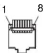
| Pin number Functions | |||
| 1 Designating Y/C input signal | |||
| 2 Designating RGB input signal | |||
| 3 Designating OPTION A-1 input signal | |||
| 4 Designating OPTION A-2 input signal | |||
| 5 | GND | ||
| 6 | Tally | lamp | ON/OFF |
| 7 | Full | screen | |
| 8 | Over | scan | |
You can allocate functions using the REMOTE menu (see page 75).
Wiring required to use the Remote Control
Connect the function you want to use with a Remote Control to the Ground (Pin 5).
SERIAL REMOTE (RS-232C) connector
D-sub 9-pin, female
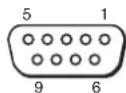
| Pin number | Signal |
| 1 | NC |
| 2 | RX |
| 3 | TX |
| 4 | NC |
| 5 | GND |
| 6 | GND |
| 7 | RTS |
| 8 | CTS |
| 9 | NC |
Available signal formats
The unit is applicable to the following signal formats. For details on the input signal available for HD15, DVI and BKM-256DD, see page 82.
*1 The frame rate is also compatible with 1/1.001.
*2 Component only
Available HD15/DVI/BKM-256DD input signal format
About the preset signal
This unit has a preset memory for signals connected to the HD15 and DVI input connectors, and BKM-256DD. When a preset signal is input, the unit automatically detects the signal type and recalls the data for the signal from the preset memory to adjust it to an optimum picture.
This unit is applicable to the following preset signals.
For the single display
PRESET 1
HD15
VESA DMT
| Resolution | Dot clock [MHz] | fH [kHz] | fV [Hz] | Sync. polarity | |
| Horizontal Vertical | |||||
| 640 × 480 60 Hz 25.175 | 31.469 59.940 Negative | Negative | |||
| 800 × 600 56 Hz 36.000 | 35.156 56.250 Positive | Positive | |||
| 800 × 600 60 Hz 40.000 | 37.879 60.317 Positive | Positive | |||
| 800 × 600 72 Hz 50.000 | 48.077 72.188 Positive | Positive | |||
| 800 × 600 75 Hz 49.500 | 46.875 75.000 Positive | Positive | |||
| 800 × 600 85 Hz 56.250 | 53.674 85.061 Positive | Positive | |||
| 1024 × 768 60 Hz 65.000 | 48.363 60.004 Negative | Negative | |||
| 1024 × 768 70 Hz 75.000 | 56.476 70.069 Negative | Negative | |||
| 1024 × 768 75 Hz 78.750 | 60.023 75.029 Positive | Positive | |||
| 1024 × 768 85 Hz 94.500 | 68.677 84.997 Positive | Positive | |||
| 1152 × 864 75 Hz 108.000 | 67.500 75.000 Positive | Positive | |||
| 1280 × 960 60 Hz 108.000 | 60.000 60.000 Positive | Positive | |||
| 1280 × 1024 60 Hz 108.000 | 63.981 60.020 Positive | Positive | |||
VESA CVT
| Resolution | Dot clock [MHz] | fH [kHz] | fV [Hz] | Sync. polarity | |
| Horizontal Vertical | |||||
| 640 × 480 60 Hz 23.625 | 29.531 59.780 Positive Negative | ||||
| 800 × 600 60 Hz 35.500 | 36.979 59.837 Positive Negative | ||||
| 1024 × 768 60 Hz 56.000 | 47.297 59.870 Positive Negative | ||||
| 1280 × 960 60 Hz 85.250 | 59.201 59.920 Positive Negative | ||||
| 1360 × 768 50 Hz 69.500 | 39.489 49.922 Negative Positive | ||||
| 1360 × 768 60 Hz 84.625 | 47.649 59.936 Negative Positive | ||||
| 1360 × 768 60 Hz 72.000 | 47.368 59.960 Positive Negative | ||||
| 1920 × 1080 50 Hz 141.375 | 55.572 49.975 Negative Positive | ||||
| 1920 × 1080 60 Hz 138. | 625 66.647 59.988 | Positive Negative | |||
| 1280 × 1024 60 Hz 91.0 | 00 63.194 59.957 | Positive Negative | |||
| 1280 × 768 50 Hz 65.1 | 25 39.518 49.959 | Negative Positive | |||
| 1280 × 768 60 Hz 80.1 | 25 47.693 59.992 | Negative Positive | |||
| 1280 × 768 75 Hz 102.8 | 75 60.091 74.926 | Negative Positive | |||
| 1280 × 768 60 Hz 68.2 | 50 47.396 59.995 | Positive Negative | |||
Others
| Resolution | Dot clock [MHz] | fH [kHz] | fV [Hz] | Sync. polarity | |
| Horizontal Vertical | |||||
| 720 × 400 70 Hz 28.322 | 31.469 | 70.087 Negative Positive | |||
| 1280 × 800 60 Hz 68.900 | 48.935 59.969 Negative | Negative | Negative | ||
DVI/BKM-256DD
Range of DVI input signal (available to 1920 × 1080/60 Hz)
Vertical frequency: 50.0 Hz to 85.1 Hz
Horizontal frequency: 31.5 kHz to 77.0 kHz
Dot clock: 25.175 MHz to 148.500 MHz
Picture size, phase: automatic discrimination by the DE (Data Enable) signal
PRESET 2
| Preset signal | fH [kHz] | fV [Hz] | |
| HD15 | 1514 × 483 | 31.5 | 60 |
| 1476 × 576 | 31.3 | 50 | |
| 1920 × 1080 | 33.75 | 60 | |
| 1920 × 1080 | 28 | 50 | |
| DVI/ BKM-256DD | 1280 × 483 | 31.5 | 60 |
| 1280 × 576 | 31.3 | 50 | |
| 1920 × 1080 | 33.75 | 60 | |
| 1920 × 1080 | 28 | 50 | |
| 1280 × 720 | 45.0 | 60 | |
| 1280 × 1024 | 63.2 | 60 | |
| 1280 × 1024 | 64.0 | 60 |
PRESET 3
| Preset signal | fH [kHz] | fV [Hz] | |
| HD15 | 720 × 483 | 31.5 | 60 |
| 720 × 576 | 31.3 | 50 | |
| 1280 × 720 | 45.0 | 60 | |
| 1280 × 720 | 37.5 | 50 | |
| DVI/ BKM-256DD | 720 × 483 | 31.5 | 60 |
| 720 × 576 | 31.3 | 50 | |
| 1280 × 720 | 45.0 | 60 | |
| 1280 × 720 | 37.5 | 50 |
PRESET 4
| Preset signal | fH [kHz] | fV [Hz] | |
| HD15 | 640 × 480 | 31.5 | 60 |
| 1024 × 768 | 48.4 | 60 | |
| 1280 × 960 | 60.0 | 60 | |
| DVI/ BKM-256DD | 1024 × 768*1 | 33.75 | 60 |
| 1024 × 768 | 48.4 | 60 | |
| 1280 × 960*1 | 33.75 | 60 | |
| 1280 × 960 | 60.0 | 60 |
*1 Available only for HD-SDI signal (1080/60I)
PRESET 5
| Preset signal | fH [kHz] | fV [Hz] | |
| HD15 | 640 × 480 31.5 | 60 | |
| 800 × 600 31.3 | 50 | ||
| 1280 × 1024 66.4 | 460 | ||
| DVI/ BKM-256DD | 800 × 600 46.9 | 75 |
PRESET 6
| Preset signal | Signal standards | |
| HD15 | 576/50P ITU-R BT.1358 | |
| 480/60P SMPTE-293M | ||
| 1080/50I SMPTE-274M | ||
| 1035/60I | SMPTE-260M/BTA S-001B | |
| 1080/60I | SMPTE-274M/BTA S-001B | |
| 720/60P SMPTE-296M | ||
| 720/50P SMPTE-296M | ||
| DVI/ BKM-256DD | 576/50P ITU-R BT.1358 | |
| 480/60P SMPTE-293M | ||
| 1080/50I SMPTE-274M | ||
| 1035/60I | SMPTE-260M/BTA S-001B | |
| 1080/60I | sMPTE-274M/BTA S-001B | |
| 720/60P SMPTE-296M | ||
| 720/50P SMPTE-296M | ||
PRESET 7 (Selected using DVI in the menu) ^*2
| Preset signal | fH [kHz] | fV [Hz] |
| 1422 × 1064 33.75 | 60 | |
| 712 × 480 15.734 | 60 | |
| 704 × 572 15.625 | 50 |
PRESET 8 (Selected using DVI in the menu) ^*2
| Preset signal | fH [kHz] | fV [Hz] |
| 1280 × 1008 33.75 | 60 | |
| 712 × 480 15.734 | 60 | |
| 704 × 572 15.625 | 50 |
*2 Available for the composite, Y/C, component, RGB or SDI signal
For the multi display
PRESET 1
HD15/DVI/BKM-256DD
VESA DMT
| Resolution | Dot clock [MHz] | fH [kHz] | fV [Hz] | Sync. polarity | |
| Horizontal | Vertical | ||||
| 1280 × 1024 60 Hz | 108.000 | 63.981 | 60.020 | Positive | Positive |
VESA CVT
| Resolution | Dot clock [MHz] | fH [kHz] | fV [Hz] | Sync. polarity | |
| Horizontal | Vertical | ||||
| 1360 × 768 60 Hz | 84.625 | 47.649 | 59.936 | Negative | Positive |
| 1360 × 768 60 Hz | 72.000 | 47.368 | 59.960 | PositiveHorizontal Vertical | NegativeHorizontal Vertical |
| 1920 × 1080 60 Hz 138. | 625 66.647 59.988 | Positive Negative | |||
| 1280 × 1024 60 Hz 91.0 | 00 63.194 59.957 | Positive Negative | |||
| 1280 × 768 60 Hz 80.1 | 25 47.693 59.992 | Negative Positive | |||
| 1280 × 768 60 Hz 68.25 | 0 47.396 59.995 | Positive Negative | |||
PRESET 2
| Preset signal | fH [kHz] | fV [Hz] | |
| HD15 | 1514 × 483 31.5 | 60 | |
| 1476 × 576 31.3 | 50 | ||
| 1920 × 1080 33.75 | 60 | ||
| 1920 × 1080 | 28 | 50 | |
| DVI/ BKM-256DD | 1280 × 483 31.5 | 60 | |
| 1280 × 576 31.3 | 50 | ||
| 1920 × 1080 33.75 | 60 | ||
| 1920 × 1080 | 28 | 50 | |
| 1280 × 720 45.0 | 60 | ||
| 1280 × 1024 | 63.2 60 | ||
| 1280 × 1024 | 64.0 60 |
PRESET 3
| Preset signal | fH [kHz] | fV [Hz] | |
| HD15 | 720 × 483 | 31.5 60 | |
| 720 × 576 | 31.3 50 | ||
| 1280 × 720 45.0 | 60 | ||
| 1280 × 720 37.5 | 50 | ||
| DVI/ BKM-256DD | 720 × 483 | 31.5 60 | |
| 720 × 576 | 31.3 50 | ||
| 1280 × 720 45.0 | 60 | ||
| 1280 × 720 37.5 | 50 |
PRESET 4
| Preset signal | fH [kHz] | fV [Hz] | |
| HD15 | 640 × 480 | 31.5 60 | |
| 1024 × 768 48.4 | 60 | ||
| 1280 × 960 60.0 | 60 | ||
| DVI/ BKM-256DD | 1024 × 768*1 | 33.75 | 60 |
| 1024 × 768 48.4 | 60 | ||
| 1280 × 960*1 | 33.75 | 60 | |
| 1280 × 960 60.0 | 60 |
*1 Available only for HD-SDI signal (1080/60I)
PRESET 5
| Preset signal | fH [kHz] | fV [Hz] | |
| HD15 | 640 × 480 | 31.5 60 | |
| 800 × 600 | 31.3 50 | ||
| 1280 × 1024 66.44 | 60 | ||
| DVI/ BKM-256DD | 800 × 600 | 46.9 75 |
PRESET 6
| Preset signal | Signal standards | |
| HD15 | 576/50P | ITU-R BT.1358 |
| 480/60P | SMPTE-293M | |
| 1080/501 | SMPTE-274M | |
| 1035/601 | SMPTE-260M/BTA S-001B | |
| 1080/601 | SMPTE-274M/BTA S-001B | |
| 720/60P | SMPTE-296M | |
| 720/50P | SMPTE-296M | |
| DVI/BKM-256DD | 576/50P ITU | R BT.1358 |
| 480/60P SMPTE-293M | ||
| 1080/50I SMPTE-274M | ||
| 1035/60I | SMPTE-260M/BTA S-001B | |
| 1080/60I | SMPTE-274M/BTA S-001B | |
| 720/60P SMPTE-296M | ||
| 720/50P SMPTE-296M | ||
PRESET 7 (Selected using DVI in the menu) ^2
| Preset signal | fH [kHz] | fV [Hz] |
| 1422 × 1064 33.75 | 60 | |
| 712 × 480 15.734 | 60 | |
| 704 × 572 15.625 | 50 |
PRESET 8 (Selected using DVI in the menu) ^2
| Preset signal | fH [kHz] | fV [Hz] |
| 1280 × 1008 33.75 | 60 | |
| 712 × 480 15.734 | 60 | |
| 704 × 572 15.625 | 50 |
*2 Available for the composite, Y/C, component, RGB or SDI signal
Dimensions
Front
When an optional stand SU-560 is attached
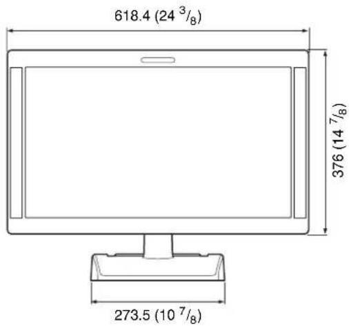
text_image
618.4 (24 3/8) 376 (14 7/8) 273.5 (10 7/8)Rear (VESA Mount Instruction)
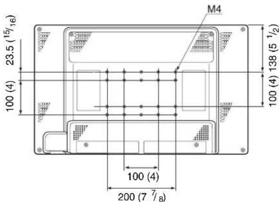
text_image
M4 23.5 (15/16) 100 (4) 100 (4) 138 (5 1/2) 100 (4) 200 (7 7/8)* Length of M4 screws (4)
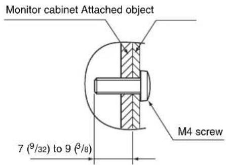
text_image
Monitor cabinet Attached object 7 (9/32) to 9 (8/8) M4 screwSide
When an optional stand SU-560 is attached
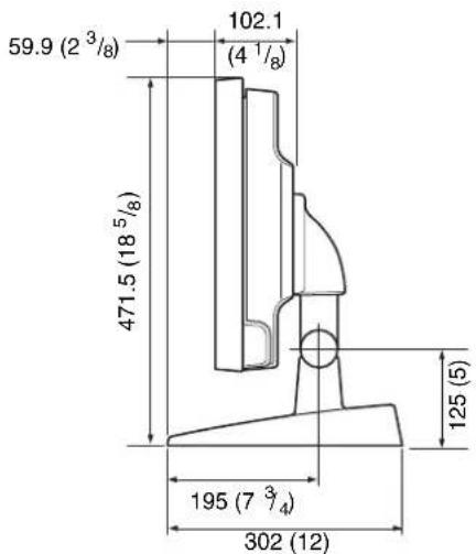
text_image
59.9 (2 3/8) 102.1 (4 1/8) 471.5 (18 5/8) 125 (5) 195 (7 3/4) 302 (12)Mass Approx. 8.1 kg (17 lb 14 oz) (when the optional stand and the input adaptor are not installed)
Approx. 8.5 kg (18 lb 12 oz) (when the optional stand is not installed and two BKM-229X are installed)
AC adaptor
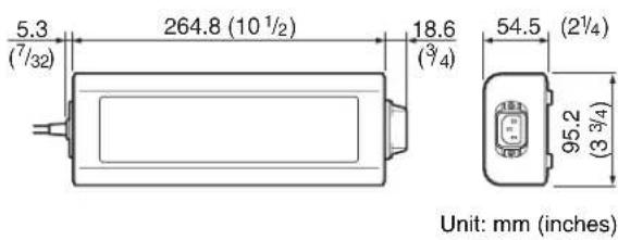
text_image
5.3 (7/32) 264.8 (10 1/2) 18.6 (3/4) 54.5 (2 1/4) 95.2 (3 3/4) Unit: mm (inches)Mass Approx. 1.2 kg (2 lb 10 oz)
Français
text_image
Diagram of a tablet device with labeled ports and connectors, showing numbered labels from 1 to 12.① Voyant Tally
text_image
Technical diagram of a computer rear panel with numbered component labels pointing to ports and connectorsnatural_image
Line drawing of a plug inserted into a socket (no text or symbols)natural_image
Line drawing of a car interior showing a door panel and seatbelt mechanism (no text or symbols)natural_image
Technical line drawing of a mechanical bracket with a screwdriver inserted, showing no text or symbolsnatural_image
Technical line drawing of a mechanical component with mounting holes and a central bracket (no text or symbols)3 Serrez les vis.
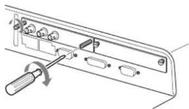
natural_image
Technical line drawing of a mechanical component with a screwdriver inserted, showing no text or symbolstext_image
World map with numbered regions highlighting major continents and key countries| TEMP COUL | NIVEAU COMPOSANT | REGLAGE NTSC | SANS SCINTILL. | |
| 1NORTH AMERICA D65 BETA7.5 7.5NON | ||||
| 2LATIN AMERICA | ||||
| PAL&PAL-N AREA | ||||
| ARGENTINA D65 SMPTE 0 OUI | ||||
| PARAGUAY D65 SMPTE 0 OUI | ||||
| URUGUAY D65 SMPTE 0 OUI | ||||
| NTSC&PAL-M AREA | ||||
| OTHER AREA D65 | BETA7 | 5 7.5 NON | ||
| 3AFRICA AUSTRALASIA EUROPE MIDDLE-EAST | D65 SMPTE 0 OUI | |||
| 4ASIA EXCEPT JAPAN | ||||
| NTSC AREA | D65 BETA7.5 7.5 NON | |||
| PAL AREA | D65 SMPTE 0 OUI | |||
| 5JAPAN | D93 | SMPTE | 0 | NON |
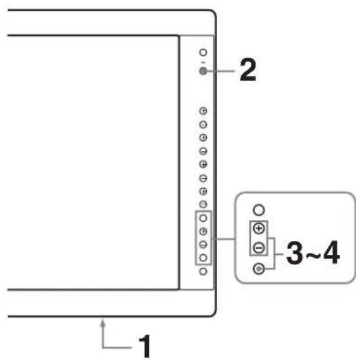
text_image
2 3~4 1natural_image
Outline map of East Asia and surrounding countries, highlighting the East China Sea region (no text or labels)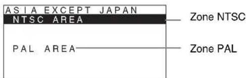
text_image
ASIA EXCEPT JAPAN NTSC AREA PAL AREA Zone NTSC Zone PALBALAYAGE (Mode balayage)
$$ \text { Type BNC } (\times 1) $$
$$ 1 \mathrm{Vp-p} \pm 3 \mathrm{dBsynchronegative} $$
$$ \text { Type BNC } (\times 1) $$
$$ 0, 3 \mathrm{Vp-p} \text {à} 4, 0 \mathrm{Vp-p} \pm \text {bipolarité} $$
text_image
Diagram of a tablet device with labeled ports and connectors, showing numbered labels from 1 to 12.① Anzeigeleuchte
text_image
Diagram of a computer rear panel with numbered ports and labeled connectorsnatural_image
Line drawing of a plug inserted into a socket (no text or symbols)3
natural_image
Technical line drawing of a mechanical component with an inset view showing internal components (no text or symbols)Netzkabel entfernen
natural_image
Mechanical assembly diagram showing a lever mechanism with no text or symbolsnatural_image
Technical line drawing of a mechanical or electronic component with ports and connectors (no text or symbols)natural_image
Technical line drawing of a device panel with screwdriver and ports (no text or symbols)text_image
World map with numbered regions highlighting major geographical areas including Asia, Africa, and parts of Europe.| FARB-TEMP. | KOMPONENTEN-PEGEL | NTSC-PEGEL | FLIMMER-FREI | |
| 1NORTH AMERICA D65 BETA7.5 7.5 | AUS | |||
②LATIN AMERICA
| PAL&PAL-N AREA | ||||
| ARGENTINA D65 SMPTE 0 EIN | ||||
| PARAGUAY D65 SMPTE 0 EIN | ||||
| URUGUAY D65 SMPTE 0 EIN | ||||
| NTSC&PAL-M AREA | ||||
| OTHER AREA | D65 | BETA7.5 7.5 | AUS | |
| 3AFRICA AUSTRALASIA EUROPE MIDDLE-EAST | D65 SM | PTE 0 EIN | ||
④ASIA EXCEPT JAPAN
| NTSC AREA | D65 BETA7.5 7.5 AUS | |||
| PAL AREA | D65 SMPTE 0 EIN | |||
| 5JAPAN | D93 | SMPTE | 0 | AUS |
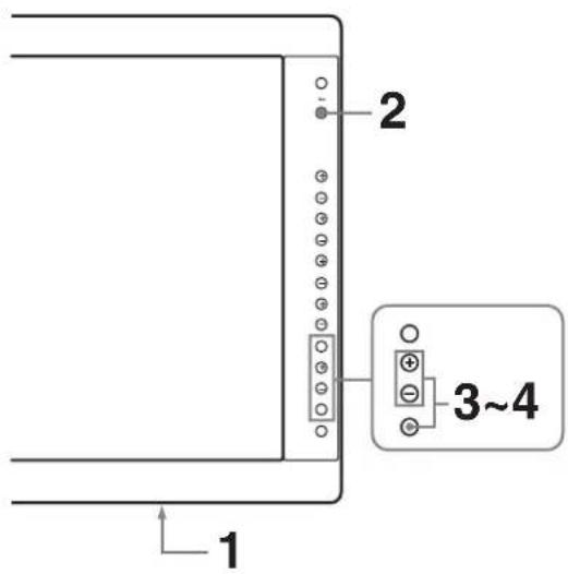
text_image
1 2 3~4natural_image
Outline map of East Asia and surrounding countries, highlighting the South Asia Sea region (no text or labels)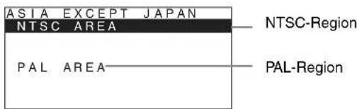
text_image
ASIA EXCEPT JAPAN NTSC AREA PAL AREA NTSC-Region PAL-RegionDC OUT: 24 V 5,0 A 5 V 0,060 A
Leistungsaufnahme
Ca. 135 W (max.)