UP-897MD - Printer SONY - Free user manual and instructions
Find the device manual for free UP-897MD SONY in PDF.

| Product Type | Monochrome thermal printer for medical use |
| Brand | Sony |
| Model | UP-897MD |
| Dimensions (W × H × D) | 154 × 88 × 240 mm |
| Weight | 2.6 kg (printer only) |
| Power Supply | 100–240 V AC, 50/60 Hz, 1.5–0.8 A |
| Print Head | Thermal head for thin paper, 1,280 dots |
| Resolution | 12.8 dots/mm (325 dpi); gray levels: 256 (8-bit) |
| Print Speed | Approx. 2 sec/image (high speed) or 3.3 sec/image (normal) |
| Image Memory | 10 images (800 KB × 8 bits per image) |
| Connectivity | Composite video input (BNC), video output BNC, remote control (stereo mini jack) |
| Supported Papers | Sony UPP-110S, UPP-110HD, UPP-110HG (110 mm rolls) |
| Main Functions | Menu settings (contrast, brightness, gamma, sharpness, image format); multiple copies; mirror or rotate printing; adjustable paper feed |
| Maintenance | Clean thermal head with provided sheet; clean platen roller with ethyl alcohol |
| Safety | Mandatory grounding; overheat protection; built-in cutter (caution) |
| Operating Temperature | 5 °C to 35 °C |
| Operating Humidity | 20 % to 80 % |
| Included Accessories | Thermal head cleaning sheet, support label, instruction manual, service list |
Frequently Asked Questions - UP-897MD SONY
User questions about UP-897MD SONY
0 question about this device. Answer the ones you know or ask your own.
Ask a new question about this device
Download the instructions for your Printer in PDF format for free! Find your manual UP-897MD - SONY and take your electronic device back in hand. On this page are published all the documents necessary for the use of your device. UP-897MD by SONY.
USER MANUAL UP-897MD SONY
For Customer in China
Video Graphic Printer
| 取扱説明書 2ページ | JP |
| Instructions for Use Page 34 | GB |
| Mode d'emploi Page 61 | FR |
| Gebrauchsanweisung Seite 94 | DE |
| Istruzioni per l'uso pagina 126 | IT |
| Manual de instrucciones página 158 | ES |
| 사용 설명서 190페이지 | KR |
Printed on recycled paper.
© 2005 Sony Corporation

安全のために
| TYPE I (Normal =標準) UPP-110S |
| TYPE II (High Density =高濃度) UPP-110HD |
| TYPE V (High Glossy =高光沢) UPP-110HG |
プリンター用紙についてのご注意

再使用禁止
natural_image
Line drawing of a hand pressing down on a front panel (no text or symbols)natural_image
Technical line drawing of a mechanical device with a downward arrow indicating motion or force (no text or symbols present)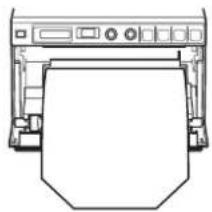
natural_image
Line drawing of a printer with paper cutout (no text or symbols)natural_image
Diagram of a printer printing a sheet of paper with directional arrows indicating process flow (no text or symbols)4 ドアを手で押して閉める。

natural_image
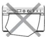
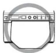
Diagram showing three different types of household appliances: a hand pressing down a printer, two crossed-out devices, and a circular device with a ring (no text or symbols present)ご注意
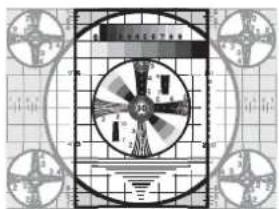
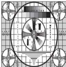
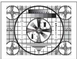
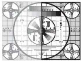
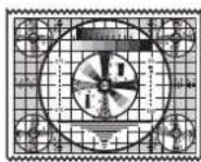
「AS:4:3」の場合
「DI: NOR」の場合
natural_image
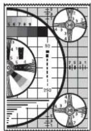
Symmetrical geometric pattern with concentric circles and radial lines, no text or symbols presentnatural_image
Illustration of a computer monitor with a hand cursor pointing at the left (no text or symbols)ブリント方向の設定モードに入ります。
液晶ディスプレイには、工場出荷時の設定
natural_image
Illustration of a kitchen appliance with a hand pointing to the control panel (no text or symbols)モニター画面
プリント画
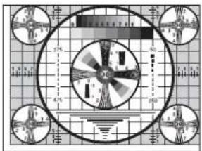
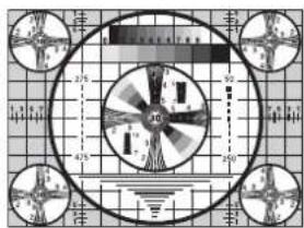
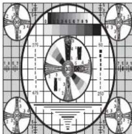
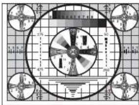
「S.H:+(*)」の場合

「S.H:0」の場合
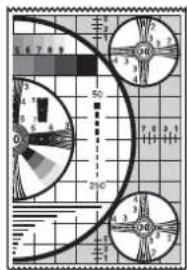

「S.H:-(*)」の場合
natural_image
Line drawing of a hand pressing a button on a front panel (no text or symbols)natural_image
Diagram of a printer or printer with a paper roll being inserted, showing no text or symbols.natural_image
Line drawing of a hand inserting a card into a printer (no text or symbols)natural_image
Line drawing of a hand pressing down on a device with a scroll (no text or symbols)The model and serial numbers are located at the rear. Record these numbers in the space provided below. Refer to these numbers whenever you call upon your Sony dealer regarding this product.
Model No. ____ Serial No. ____
WARNING
To reduce the risk of fire or electric shock, do not expose this apparatus to rain or moisture.
To avoid electrical shock, do not open the cabinet. Refer servicing to qualified personnel only.
No modification of this equipment is allowed.
THIS APPARATUS MUST BE EARTHED.
To disconnect the main power, unplug the power plug. When installing the unit, incorporate a readily accessible disconnect device in the fixed wiring, or connect the power plug to an easily accessible socket-outlet near the unit. Do not position the ME equipment where it is difficult to unplug the power plug. If a fault should occur during operation of the unit, operate the disconnect device to switch the power supply off, or unplug the power plug.
Symbols on the products

This symbol indicates the equipotential terminal which brings the various parts of a system to the same potential.

This symbol is intended to alert the user to the presence of important operating and maintenance (servicing) instructions in the literature accompanying the appliance.

This symbol indicates the manufacturer, and appears next to the manufacturer's name and address.

Refer to the operating instructions
Follow the directions in the operating instructions for parts of the unit on which this mark appears.
For the customers in the U.S.A.
This equipment has been tested and found to comply with the limits for a Class A digital device, pursuant to Part 15 of the FCC Rules. These limits are designed to provide reasonable protection against harmful interference when the equipment is operated in a commercial environment. This equipment generates, uses, and can radiate radio frequency energy and, if not installed and used in accordance with the instruction manual, may cause harmful interference to radio communications. Operation of this equipment in a residential area is likely to cause harmful interference in which case the user will be required to correct the interference at his own expense.
You are cautioned that any changes or modifications not expressly approved in this manual could void your authority to operate this equipment.
All interface cables used to connect peripherals must be shielded in order to comply with the limits for a digital device pursuant to Subpart B of Part 15 of FCC Rules.
For the customers in Canada
This unit has been certified according to Standard CAN/CSA-C22.2 No.60601-1.
For the customers in the U.S.A and Canada
When you use this product connected to 240 V single phase, be sure to connect this product to a center tapped circuit.
Important safeguards/notices for use in the medical environments
-
All the equipments connected to this unit shall be certified according to Standard IEC60601-1, IEC60950-1, IEC60065 or other IEC/ISO Standards applicable to the equipments.
-
Furthermore all configurations shall comply with the system standard IEC60601-1-1. Everybody who connects additional equipment to the signal input part or signal output part configures a medical system, and is therefore, responsible that the system complies with the requirements of the system standard IEC60601-1-1. If in doubt, consult the qualified service personnel.
-
The leakage current could increase when connected to other equipment.
-
For this particular equipment, all accessory equipment connected as noted above, must be connected to mains via an additional isolation transformer conforming with the construction
requirements of IEC60601-1 and providing at least Basic Insulation.
- This equipment generates, uses, and can radiate radio frequency energy. If it is not installed and used in accordance with the instruction manual, it may cause interference to other equipment. If this unit causes interference (which can be determined by
unplugging the power cord from the unit), try these measures: Relocate the unit with respect to the susceptible equipment. Plug this unit and the susceptible equipment into different branch circuit.
Consult your dealer. (According to standard IEC60601-1-2 and CISPR11, Class B, Group 1)
Important EMC notices for use in the medical environments
- The UP-897MD needs special precautions regarding EMC and needs to be installed and put into service according to the EMC information provided in this instructions for use.
- The portable and mobile RF communications equipment such as cellular phones can affect the UP-897MD.
Warning
The use of accessories and cables other than those specified, with the exception of replacement parts sold by Sony Corporation, may result in increased emissions or decreased immunity of the UP-897MD.
| Guidance and manufacturer's declaration-electromagnetic emissions | ||
| The UP-897MD is intended for use in the electromagnetic environment specified below.The customer or the user of the UP-897MD should assure that it is used in such an environment. | ||
| Emission test Compliance Electromagnetic environment-guidance | ||
| RF emissionsCISPR 11 | Group 1 | The UP-897MD uses RF energy only for its internal function. Therefore, its RF emissions are very low and are not likely to cause any interference in nearby electronic equipment. |
| RF emissionsCISPR 11 | Class B | The UP-897MD is suitable for use in all establishments, including domestic establishments and those directly connected to the public low-voltage power supply network that supplies buildings used for domestic purposes. |
| Harmonic emissionsIEC 61000-3-2 | Class A | |
| Voltage fluctuations/flicker emissionsIEC 61000-3-3 | Complies | |
Warning
If the UP-897MD should be used adjacent to or stacked with other equipment, it should be observed to verify normal operation in the configuration in which it will be used.
| Guidance and manufacturer's declaration - electromagnetic immunity | |||
| The UP-897MD is intended for use in the electromagnetic environment specified below. The customer or the user of the UP-897MD should assure that it is used in such as environment. | |||
| Immunity test | IEC 60601 test level | Compliance level E | Electromagnetic environment-guidance |
| Electrostatic discharge (ESD)IEC 61000-4-2 | ±6 kV contact±8 kV air | ±6 kV contact±8 kV air | Floors should be wood, concrete or ceramic tile. If floors are covered with synthetic material, the relative humidity should be at least 30%. |
| Electrical fast transient/burstIEC 61000-4-4 | ±2 kV for power supply lines±1 kV for input/output lines | ±2 kV for power supply lines±1 kV for input/output lines | Mains power quality should be that of a typical commercial or hospital environment. |
| SurgeIEC 61000-4-5 | ±1 kV differential mode±2 kV common mode | ±1 kV differential mode±2 kV common mode | Mains power quality should be that of a typical commercial or hospital environment. |
| Voltage dips, short interruptions and voltage variations on power supply input linesIEC 61000-4-11 | < 5% UT(>95% dip in UT)for 0.5 cycle40% UT(60% dip in UT)for 5 cycles70% UT(30% dip in UT)for 25 cycles< 5% UT(>95% dip in UT)for 5 sec | < 5% UT(>95% dip in UT)for 0.5 cycle40% UT(60% dip in UT)for 5 cycles70% UT(30% dip in UT)for 25 cycles< 5% UT(>95% dip in UT)for 5 sec | Mains power quality should be that of a typical commercial or hospital environment. If the user of the UP-897MD requires continued operation during power mains interruptions, it is recommended that the UP-897MD be powered from an uninterruptible power supply or a battery. |
| Power frequency (50/60 Hz)magnetic fieldIEC 61000-4-8 | 3 A/m 3 A/m Power | frequency magnetic fields should be at least characteristic of a typical location in a typical commercial or hospital environment. | |
| NOTE: UT is the a.c. mains voltage prior to application of the test level. | |||
| Conducted RF | 3 Vrms | 3 Vrms | Portable and mobile RF communications equipment should be used no closer to any part of the UP-897MD, including cables, than the recommended separation distance calculated from the equation appliance to the frequency of the transmitter.Recommended separation distance d = 1.2 |
| IEC 61000-4-6 | 150 kHz to 80 MHz | ||
| Radiated RF | 3 V/m | 3 V/m | d = 1.2 80 MHz to 800 MHz d = 2.3 800 MHz to 2.5 GHzWhere P is the maximum output power rating of the transmitter in watts (W) according to the transmitter manufacturer and d is the recommended separation distance in meters (m).Field strengths from fixed RF transmitters, as determined by an electromagnetic site survey, ^a should be less than the compliance level in each frequency range. ^b Interference may occur in the vicinity of equipment marked with following symbol: |
| IEC 61000-4-3 | 80 MHz to 2.5 GHz | ||
| NOTE 1: At 80 MHz and 800 MHz, the higher frequency range applies.NOTE 2: These guidelines may not apply in all situations. Electromagnetic propagation is affected by absorption and reflection from structures, objects and people. | |||
| a Field strengths from fixed transmitters, such as base stations for radio (cellular/cordless) telephones and land mobile radios, amateur radio, AM and FM radio broadcast and TV broadcast cannot be predicted theoretically with accuracy. To assess the electromagnetic environment due to fixed RF transmitters, an electromagnetic site survey should be considered. If the measured field strength in the location in which the UP-897MD is used exceeds the applicable RF compliance level above, the UP-897MD should be observed to verify normal operation. If abnormal performance is observed, additional measures may be necessary, such as reorienting or relocating the UP-897MD.b Over the frequency range 150 kHz to 80 MHz, field strengths should be less than 3 V/m.Recommended separation distances between portable and mobile RF communications equipment and the UP-897MD | |||
| The UP-897MD is intended for use in an electromagnetic environment in which radiated RF disturbances are controlled. The customer or the user of the UP-897MD can help prevent electromagnetic interference by maintaining a minimum distance between portable and mobile RF communications equipment (Transmitters) and the UP-897MD as recommended below, according to the maximum output power of the communications equipment. | |||
| Rated maximum output power of transmitter W | Separation distance according to frequency of transmitter m | ||
| 150 kHz to 80 MHz d = 1.2 √P | 80 MHz to 800 MHz d = 1.2 √P | 800 MHz to 2.5 GHz d = 2.3 √P | |
| 0.01 0.12 0.12 0.23 | |||
| 0.1 0.38 0.38 0.73 | |||
| 1 1.2 1.2 2.3 | |||
| 10 3.8 3.8 7.3 | |||
| 100 12 12 23 | |||
| For transmitters rated a maximum output power not listed above, the recommended separation distance d in meters (m) can be estimated using the equation applicable to the frequency of the transmitter, where P is the maximum output power rating of the transmitter in watts (W) according to the transmitter manufacturer.NOTE 1: At 80 MHz and 800 MHz, the separation distance for the higher frequency range applies.NOTE 2: These guidelines may not apply in all situations. Electromagnetic propagation is affected by absorption and reflection from structures, objects and people. | |||
Caution
When you dispose of the unit or accessories, you must obey the law in the relative area or country and the regulation in the relative hospital.
Warning on power connection
Use a proper power cord for your local power supply.
-
Use the approved Power Cord (3-core mains lead) / Appliance Connector / Plug with earthing-contacts that conforms to the safety regulations of each country if applicable.
-
Use the Power Cord (3-core mains lead) / Appliance Connector / Plug conforming to the proper ratings (Voltage, Ampere).
If you have questions on the use of the above Power Cord / Appliance Connector / Plug, please consult a qualified service personnel.
Warning on power connection for medical use
Please use the following power supply cord.
With connectors (plug or female) and cord types other than those indicated in this table, use the power supply cord that is approved for use in your area.
| United States and Canada | |
| Plug Type | HOSPITAL GRADE* |
| Cord Type | Min.Type SJTMin.18 AWG |
| Minimum Rating for Plug and Appliance Couplers | 10 A/125 V |
| Safety Approval | UL Listed and CSA |
*Note: Grounding reliability can only be achieved when the equipment is connected to an equivalent receptacle marked 'Hospital Only' or 'Hospital Grade'.
For the customers in Europe
This product has been manufactured by or on behalf of Sony Corporation, 1-7-1 Konan Minato-ku Tokyo, 108-0075 Japan. Inquiries related to product compliance based on European Union legislation shall be addressed to the authorized representative, Sony Deutschland GmbH, Hedelfinger Strasse 61, 70327 Stuttgart, Germany. For any service or guarantee matters, please refer to the addresses provided in the separate service or guarantee documents.
For kundene i Norge
Dette utstyret kan kobles til et IT-strømfordelingssystem.
Table of Contents
Getting Started
Overview 40
Location and Function of Parts and Controls ..40
Front Panel 40
Rear Panel 41
Connections 42
Paper 42
Paper You Can Use 42
Loading Paper in the Unit 43
Loading Paper 43
Operation
Adjustments and Settings Using the Menu ..... 45
Menu Flow 45
Menu List 46
Basic Menu Operations 49
Registering Menu Settings 50
Printing the Menu List 51
Printing 51
Starting a Print Job 51
Selecting the Printing Direction and Image Size 53
Adjusting the Contrast and Brightness .... 54
Others
Precautions 56
On Safety 56
On the Printer Carriage 56
On Installation 56
Maintenance ....57
Cleaning the Cabinet 57
Cleaning the Thermal Head 57
Cleaning the Platen Roller 58
Specifications 59
Troubleshooting 60
Error Messages 61
Index 62
Getting Started
Overview
Quiet, High Quality, Fast Printing
- Employs a thin thermal head with a built-in high speed drive IC, capable of high resolution images of 12.8 dots/mm.
- Print speeds of approximately 1 high quality image (A-7 size single printout) every 2 seconds when printing at high speed (when “SP:HI” is selected in “SPEED” menu item).
- Monochrome printing with up to 256 shades of gradation.
- Built-in temperature correction circuits prevent temperature changes which could cause blurred prints.
Easy printer settings using a menu
You can make up the settings to meet your requirements using a menu. You can store up to three settings as a set of user settings.
Easy Paper Loading
Free access to the door panel allows you to drop paper into the unit for easy loading.
Location and Function of Parts and Controls
For more details, see the referenced page numbers enclosed in parentheses ().
Front Panel
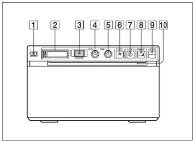
1①Power ON/OFF Switch (43, 49, 51, 57)
Press to switch to ON to turn the power on. The back light on the LCD lights in green.
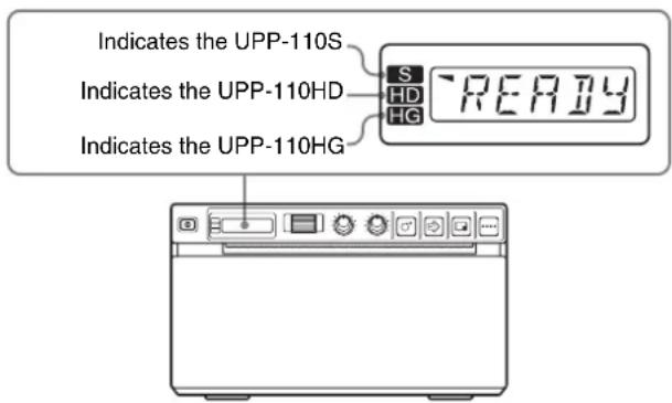
2 Printer window display (LCD: liquid crystal display) (45, 51)
The back light lights in green when the unit operates normally. Also, in normal operation, the paper currently selected is indicated by the pointer on the LCD. For detailed information on the paper, see “Paper” on page 42 and “Paper currently selected” on page 52. If an error occurs, a corresponding alarm message is displayed. During menu operations, menu items and settings are displayed
3Jog dial (49, 57)
Used to make menu operations.
4CONTR (contrast) control (54)
Adjusts the contrast of the printouts.
5 BRIGHT (brightness) control (54)
Adjusts the brightness of the printouts.
6 FEED button (44, 52)
Hold down to feed paper. While a print job is in progress, press to cancel the print job.
7 COPY button (52)
Prints another copy of the previous printout.
You can make only one copy each time you press this button regardless of the print quantity set using the menu.
8 PRINT button
Prints the image currently displayed on the video monitor. The image displayed when you press the PRINT button is stored in memory.
9 OPEN button (43, 52)
Press to open the paper door. While a print job is in progress, press to cancel the print job.
10 Paper cutter
Cuts the paper as each image is printed.
Rear Panel
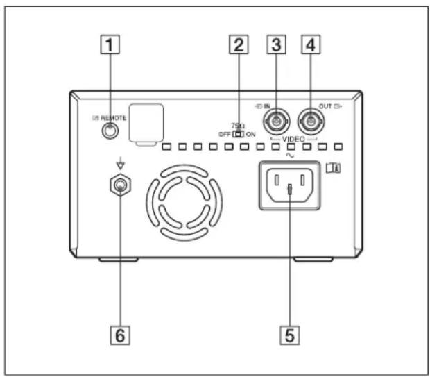
1 REMOTE connector (42)
Connects the RM-91 remote control unit or the FS-24 foot switch for controlling print operation from a distance.
275 Ω select switch
ON: When nothing is connected to the VIDEO OUT connector, set the switch to this position. OFF: When a video monitor or other video equipment is connected to the VIDEO OUT connector, set the switch to this position.
3→VIDEO IN (input) connector (BNC type)
Connect to the video output connector of the video equipment.
4 ➕ VIDEO OUT (output) connector (BNC type)
Connect to the video input connector of the video monitor. The output signal depends on the setting of the “VIDEO” item of the menu.
5\~AC IN connector
Use a proper power cord for your local power supply. Refer to “Warning on power connection” on page 38 and “Warning on power connection for medical use” on page 38.
Used to connect to the equipotential plug to bring the various parts of a system to the same potential. Refer to “Important safeguards/notices for use in the medical environments” on page 34.
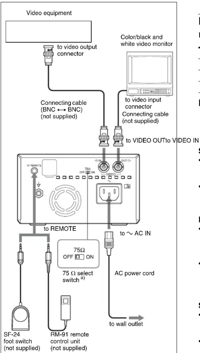
Connections
Notes
- Turn off the power to each device before making any connections.
- Connect the AC power cord last.
flowchart
graph TD
    A["Video equipment"] --> B["to video output connector"]
    B --> C["Connecting cable (BNC ↔ BNC) (not supplied)"]
    C --> D["to VIDEO OUT to VIDEO IN"]
    D --> E["75Ω select switch a)"]
    E --> F["75Ω OFF ON"]
    F --> G["AC power cord"]
    G --> H["to ~ AC IN"]
    H --> I["to wall outlet"]
    I --> J["SF-24 foot switch (not supplied)"]
    I --> K["RM-91 remote control unit (not supplied)"]
a) Set the 75 Ω select switch as follows. ON: When nothing is connected to the VIDEO OUT connector, set the switch to this position. OFF: When a video monitor or other video equipment is connected to the VIDEO OUT connector, set the switch to this position.
Paper
Use only Sony UPP-110S/110HD/110HG paper designed for use with this unit. High print quality cannot be guaranteed if any other paper is used with this unit, and such paper could damage the unit.
You cannot use the UPP-110HA as specified for the UP-880/890MD series printer.
Paper You Can Use
Print paper characteristics are as follows.
Print Characteristics Paper Type
| TYPE I (Normal) UPP-110S |
| TYPE II (High Density) UPP-110HD |
| TYPE V (High Glossy) UPP-110HG |
Notes on storing and handling paper

Do not re-use
Doing so may result in malfunction and negatively affect printing results.
Storing unused paper
- Stored unused paper at a temperature below 30^ (86°F) in a dry location that is not exposed to direct sunlight.
- Do not store unused paper near volatile liquids or allow the paper to contact any organic volatile liquid, cellophane tape, or any compound of vinyl chloride.
Loading paper
- Handle the paper carefully when loading to avoid touching the printing surface with your fingers. Perspiration or oil from you hands could cause pictures to blur.
- After removing the label from the leading edge of the paper, pull the paper out 15\~20 cm (about 6\~8 in.) before printing. Label adhesive remaining on the paper could spoil a picture.
Storing printouts
- To prevent printouts from fading or changing color, store them in a cool, dry location where the temperature is not higher than 30^ (86°F).
- Store printouts in a polypropylene pouch or between sheets of paper that contain no plastic.
- Do not store printouts where they will be exposed to direct sunlight or high humidity.
- Do not store printouts near volatile liquids or allow the prints to contact any organic volatile liquid, cellophane tape, or any compound of vinyl chloride.
- To prevent fading, do not stack printouts on or under a diazo copy sheet.
- To mount printouts on another sheet of paper, use double-sides tape or a water base adhesive.
- Do not incinerate waste printer paper.
Loading Paper in the Unit
Notes
- Before loading paper in the unit, see “Notes on storing and handling paper” (page 42).
• Always handle paper carefully when loading to avoid adversely affecting the quality of the printouts. Never bend or crease the paper and never touch the printing surface with your fingers. Fingerprints perspiration can blur printing. - Do not use any paper other than UPP-110S/110HD/110HG paper. (page 42)
- Be sure to set the “MEDIA” menu item to the paper to be used. You can confirm the media currently selected on the LCD. (page 47)
Loading Paper
Caution
A paper cutter is mounted with the unit. When loading paper, be careful not to touch the paper cutter. Touching the paper cutter may cause injury.
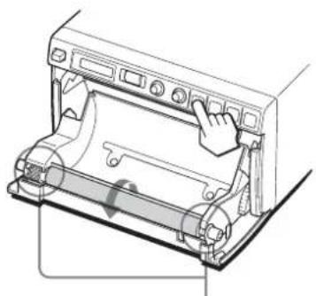
1 Press the power ON/OFF switch to turn the unit on. When paper is not loaded yet, the back light on the LCD lights in umber and the message "EMPTY" is displayed.
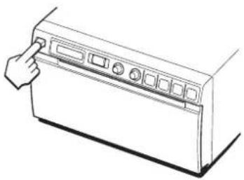
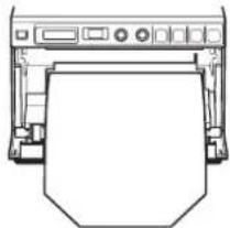
natural_image
Line drawing of a hand pressing down on a front panel (no text or symbols)2 Press the OPEN button to open the paper door.
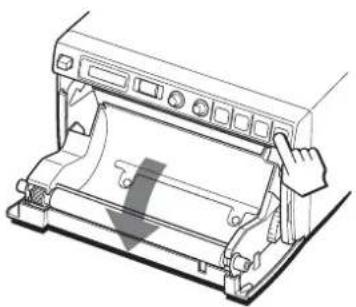
natural_image
Technical line drawing of a mechanical device with a downward arrow indicating motion or force (no text or symbols)3 Remove the label from the leading edge of the paper, pull out about 15\~20 cm (about 6\~8 in.) of the paper, and then set the paper roll in the paper tray.
Note
To avoid exposing the paper to dust, dirt, etc. always handle it carefully when removing from its package and loading it in the unit. Paper exposed to dirt or dust cannot be used for printing.
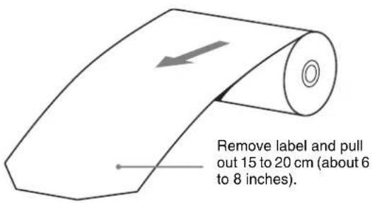
Load the paper with the printing side (heat sensitive side) up. Printing is not possible if the paper is reversed.
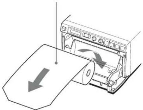
natural_image
Illustration of a printer printing a sheet of paper with directional arrows (no text or symbols)
natural_image
Line drawing of a printer with paper sheet and control panel (no text or symbols)Make sure that the paper is set straight.
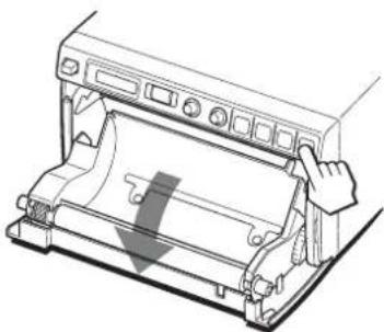
4 Close the paper door and press on it to shut it.
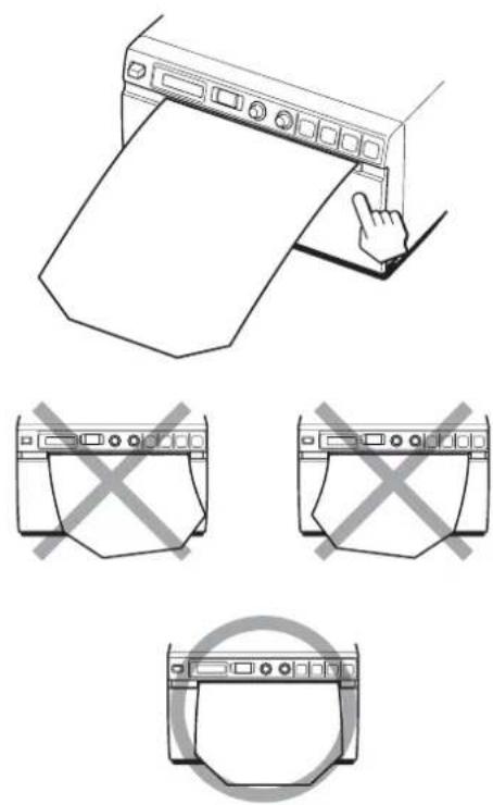
Notes
- Make sure that the paper is loaded straight. If it is skewed, this could cause the paper to jam.
- If you did not pull out enough paper in step 3, press the FEED button on the operation panel to feed some more paper out of the unit without pulling out the paper.
Operation
Adjustments and Settings Using the Menu
You can carry out adjustments and settings to meet your requirements. Those settings and adjustments are retained even if the unit is turned off.
You can set up the unit according to its intended purpose, connected equipments or your individual preferences.
You can store up to three settings as a set of user settings.
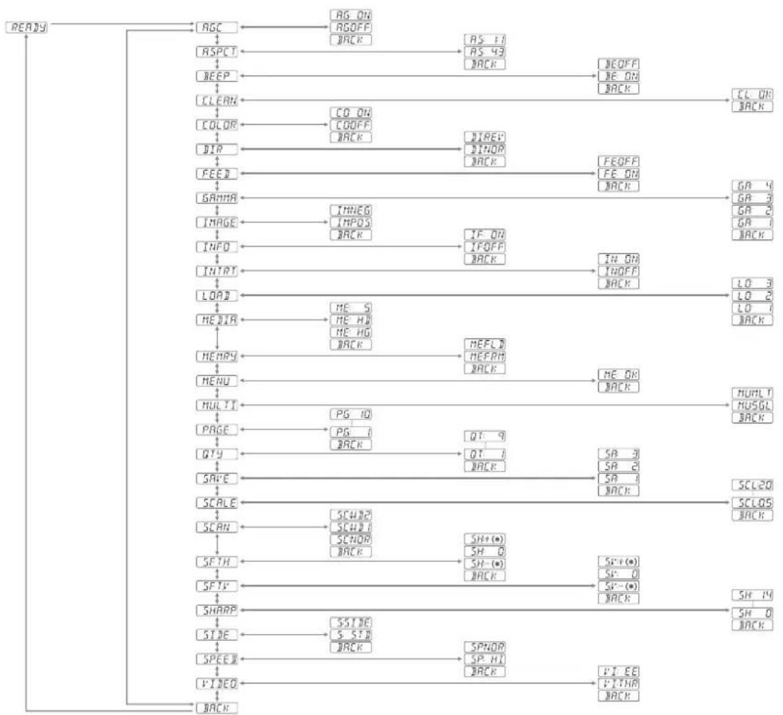
Menu Flow
The contents displayed on the LCD changes in sequence as you turn the jog dial as shown in the following menu
flow chart, and you can make the settings for each menu item.
flowchart
graph TD
    A["READY"] --> B["AGC"]
    B --> C["AS ON"]
    B --> D["ROFF"]
    D --> E["BACK"]
    C --> F["AS 11"]
    F --> G["AS 43"]
    G --> H["BACK"]
    H --> I["NEOFF"]
    I --> J["NE ON"]
    J --> K["BACK"]
    K --> L["CL ON"]
    L --> M["BACK"]
    B --> N["ASPT"]
    N --> O["BEEP"]
    O --> P["CLEAN"]
    P --> Q["COLOR"]
    Q --> R["DIP"]
    R --> S["FEED"]
    S --> T["GRAMA"]
    T --> U["IMAGE"]
    U --> V["INFO"]
    V --> W["INITAT"]
    W --> X["LOAD"]
    X --> Y["HEZIA"]
    Y --> Z["HEARS"]
    Z --> AA["MENU"]
    AA --> AB["HULTI"]
    AB --> AC["PAGE"]
    AC --> AD["QTY"]
    AD --> AE["SAFE"]
    AE --> AF["SCALE"]
    AF --> AG["SCAN"]
    AG --> AH["SFTH"]
    AH --> AI["SFYV"]
    AI --> AJ["SHARP"]
    AJ --> AK["SIZE"]
    AK --> AL["SPEED"]
    AL --> AM["VINEO"]
    AM --> AN["BACK"]

    B --> AO["AS ON"]
    AO --> AP["BEEP"]
    AP --> AQ["CLEAN"]
    AQ --> AR["COLOR"]
    AR --> AS["DIP"]
    AS --> AT["FEED"]
    AT --> AU["GRAMA"]
    AU --> AV["IMAGE"]
    AV --> AW["INFO"]
    AW --> AX["INITAT"]
    AX --> AY["LOAD"]
    AY --> AZ["HETIA"]
    AZ --> BA["HEARS"]
    BA --> BB["MENU"]
    BB --> BC["HULTI"]
    BC --> BD["PAGE"]
    BD --> BE["QTY"]
    BE --> BF["SALE"]
    BF --> BG["SCAN"]
    BG --> BH["SFTH"]
    BH --> BI["SFYV"]
    BI --> BJ["SHARP"]
    BJ --> BK["SIDE"]
    BK --> BL["SPEED"]
    BL --> BM["VINEO"]

    C --> BN["AS ON"]
    BN --> BO["BEEP"]
    BO --> BP["CLEAN"]
    BP --> BQ["COLOR"]
    BQ --> BR["DIP"]
    BR --> BS["FEED"]
    BS --> BT["GRAMA"]
    BT --> BU["IMAGE"]
    BU --> BV["INFO"]
    BV --> BW["INITAT"]
    BW --> BX["LOAD"]
    BX --> BY["HETIA"]

    D --> BZ["BEEP"]
    BZ --> CA["CLEAN"]
    CA --> CB["COLOR"]
    CB --> CC["DIP"]
    CC --> DD["FEED"]
    DD --> DP["GRAMA"]

    E --> Q["BEEP"]
    Q --> R["CLEAN"]
    R --> SC["COLOR"]

    F --> S["BEEP"]
    S --> T["CLEAN"]
    T --> U["COLOR"]

    G --> U
    H --> U
    I --> U
    J --> U
    K --> U
    L --> U
About * in the "SFT:H" and "SFT:V" menu items
* means the numeric value displayed by turning the jog dial. This numeric value changes depending on the settings of
"SCALE", "SCAN" and "SIDE", and the signal system of the image to be captured.
Menu List
This section describes the menus displayed as you turn the jog dial. The setting surrounded by ____ indicates the factory setting.
| Item Function Settings | ||
| AGC To adjust the input signal to the optimum printing level | AG:ON: Adjusts the input signal to the optimum level, when the printout image appears too dark or too light. :OFF : Normally select this setting.BACK: Cancels the setting change and returns to the item selection column. | |
| ASPCTa) | To select the aspect ratio | AS:1:1: Prints a video signal with an aspect ratio of 1:1. :4:3 : Normally select this setting.BACK: Cancels the setting change and returns to the item selection column |
| BEEP To select whether the operation and error tones sound | BE: OFF: The operation tone does not sound. :ON : The operation and error tones sound.BACK: Cancels the setting change and returns to the item selection column. | |
| CLEAN To start head cleaning | :OK : Starts the head cleaning. Be sure to use the supplied cleaning sheet.BACK: Cancels the head cleaning and returns to the item selection column. | |
| COLOR To select the input signal to be printed | CO:ON: Prints the color signal. :OFF : Prints the black and white signal.BACK: Cancels the setting change and returns to the item selection column. | |
| DIRb) | To select whether the top or bottom of the screen is to be printed first | DI: REV: Starts to print in the reverse direction (from the top of the screen). :NOR : Starts to print in the normal direction (from the bottom of the screen).BACK: Cancels the setting change and returns to the item selection column. |
| Item Function Settings | ||
| FEED To select the paper feed method to be used after printing | FE: OFF: Feeds less paper between prints to conserve paper, or when printing multiple pictures on the same sheet. More pictures can be printed on one sheet, but because there is so little space between printed pictures, you must press the FEED button before cutting the paper.FE: ON: Feeds extra blank paper between prints.BACK: Cancels the setting change and returns to the item selection column. | |
| GAMMA (When the “ME:S” is selected in “MEDIA” is selected, GAMMA is fixed to TONE 1.) | To select the tone of the printouts (density gradation) | GA:4: TONE 4 Softest gradationGA:3: TONE 3 Hard gradationGA:2: TONE 2 Standard GA:1: TONE 1 Soft gradationBACK: Cancels the setting change and returns to the item selection column. |
| IMAGE To set the printout to either positive printout or negative printout | IM:NEG: Makes negative printouts.IM:POS: Makes normal printouts.BACK: Cancels the setting change and returns to the item selection column. | |
| INFO To select whether or not the print conditions (such as contrast, brightness, gammas and sharpness information) are printed under the image | IF:ON: Prints the information.IF:OFF: Does not print the information.BACK: Cancels the setting change and returns to the item selection column. | |
| INTRT To change the operation of printing interruption | IN:ON: Stops printing by pressing the PRINT button during printing and prints a new image captured at instant you pressed the PRINT button.[IN:OFF]: Does not stop printing even if the PRINT button is pressed. After completing the current printing, the unit prints the image captured at instant you pressed the PRINT button.BACK: Cancels the setting change and returns to the item selection column. | |
| LOAD To load the registered settings | LO:3: Loads the “SA:3” settings registered using the “SAVE” menu item. LO:2: Loads the “SA:2” settings registered using the “SAVE” menu item. [LO:1]: Loads the “SA:1” settings registered using the “SAVE” menu item BACK: Cancels the setting change and returns to the item selection column. | |
| MEDIA To select the type of paper | ME:S: Uses the UPP-110S. ME:HD: Uses the UPP-110HD. [ME:HG]: Uses the UPP-110HG BACK: Cancels the setting change and returns to the item selection column. | |
| MEMRY To select the memory mode | ME:FLD: When printing fast-moving images (such as a ball being thrown), the printout may be blue. If this happens, select this setting. [ME:FRM]: Normally select this setting. BACK: Cancels the setting change and returns to the item selection column. | |
| MENU To print the menu settings currently selected | [ME:OK]: Prints the menu list currently set. BACK: Cancels printing and goes back to its item column. | |
| MULTI To specify the number of images to be printed on one sheet of the printout | MU:MLT: Prints two images on one sheet of the printout (two reduced images). [MU:SGL]: Prints one image. (full-size image). BACK: Cancels the setting change and returns to the item selection column. | |
| PAGE (This item is not displayed when “MU:MLT” is selected in “MULTI.”) | Each time you press the PRINT button, the image is stored in memory. Up to ten images can be stored. You can select the desired image from 10 kinds of images stored in memory and make a printout. | [PG:1] to PG:10: Prints by selecting the desired ONE image from among images 1 to10 and pressing the COPY button. BACK: Cancels the setting change and returns to the item selection column. |
| Item Function Settings | ||
| QTY To set the print quantity | QT:1 to QT:9: Makes the same printouts. You can select the desired number of same printongs between 1 and 9.BACK: Cancels the setting change and returns to the item selection column. | |
| SAVE To register up to three kinds of settings | SA:3: Registers the menu settings as No.3.SA:2: Registers the menu settings as No.2.SA:1: Registers the menu settings as No.1.BACK: Cancels the setting change and returns to the item selection column. | |
| SCALE To enlarge or reduce the image to be printed | The scale can be set between SCL:2.0 (two times) and SCL:0.5 (one half) in increments of 0.5.[SCL:1.0] is the factory setting.BACK: Cancels the setting change and returns to the item selection column. | |
| SCAN^c) | To set the range of the image to be printed | The range is widened in the sequence of SC:NOR,SC:WD1and SC:WD2.BACK: Cancels the setting change and returns to the item selection column. |
| SFT.H | To specify the horizontal position of the image to be printed | [S.H:0]: Adjusts the horizontal position. The numeric value displayed by turning the jog dial depends on the settings of “SCALE”, “SCAN”, and “SIDE”, and the signal system of the image to be captured.BACK: Cancels the setting change and returns to the item selection column. |
| SFT.V | To specify the vertical position of the image to be printed | [S.V:0]: Adjusts the vertical position. The numeric value displayed by turning the jog dial depends on the settings of “SCALE”, “SCAN”, and “SIDE”, and the signal system of the image to be captured.BACK: Cancels the setting change and returns to the item selection column. |

| Item Function Settings | ||
| SHARP To adjust the sharpness of the printout | You can set the sharpness to any of 15 steps, from 0 to 14.At a setting of 0, the outline of the printout is not emphasized.A setting of step 2 is the factory setting.BACK: Cancels the setting change and returns to the item selection column. | |
| SIDE^d) | To select the direction in which the image is to be printed | S:SIDE: Prints the image rotated by 90 degrees counterclockwise. S:STD :Prints the image in the same direction as that displayed on the monitor.BACK: Cancels the setting change and returns to the item selection column. |
| SPEED (When “ME:HD” is selected in “MEDIA,” the printing speed is fixed to “SP:NOR” and this item is not displayed.) | To select the printing speed | SP:NOR: Prints at the normal speed. SP:HI : Prints at high speed.BACK: Cancels the setting change and returns to the item selection column.NoteWhen “SP:HI” is selected, the power consumption is a little higher, compared with printing at the normal speed. |
| VIDEO To select the video signal output from the VIDEO OUT connector on the rear panel | VI:EE: Outputs the signal after it is processed by the printer. VI:THR : Outputs the signal directly without processing.BACK: Cancels the setting change and returns to the item selection column. | |
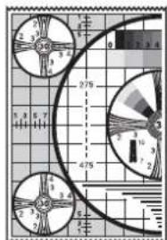
| BACK To exit menu mode | Display this item and then press the jog dial. The unit exits the menu mode and “READY” is displayed on the LCD. | |
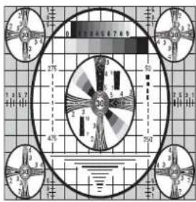
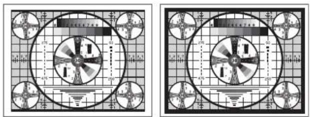
a) The aspect ratio is as follows.
When AS:4:3 is selected
When AS:1:1 is selected
b) The printing direction is as follows.
When DI:NOR is selected When DI: REV is selected
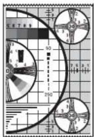
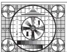
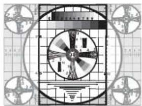
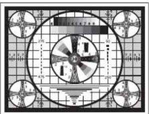
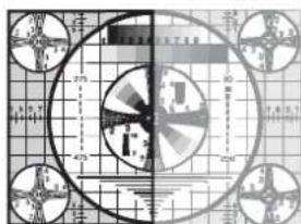
c) The range of the image to be printed is as follows.
When SC:NOR is selected
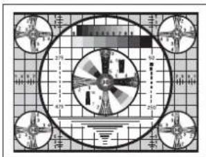
When SC:WD1 is selected
natural_image
Pure electrical circuit lines without any symbolsWhen SC:WD2 is selected
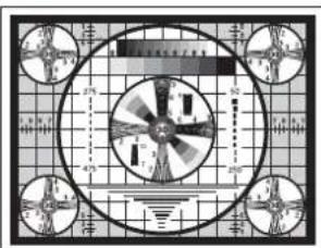
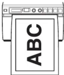
d) The print direction of the images printed is as follows.
Image displayed on the monitor

Printouts
When S:STD is selected. When S:SIDE is selected
Basic Menu Operations
This section describes the basic menu operation which are common to each menu, taking “How to set the printing direction” as an example.
1 Press the power ON/OFF switch to ON to turn the unit on.
The back light on the LCD lights in green.
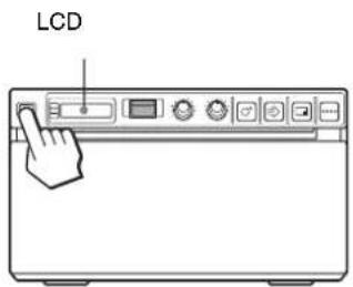
2 Confirm that "READY" is displayed on the LCD, and press the jog dial.
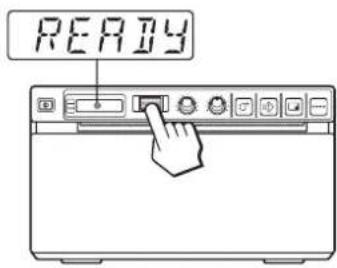
The unit enters the menu mode.
When you perform a menu operation for the first time after you purchase the unit, the top item of the "AGC" menu is displayed.
If you have performed a menu operation already, the item that you set last is displayed.
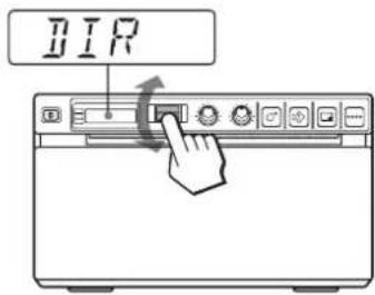
3 Display "DIR" by turning the jog dial up or down.
4 Press the jog dial.
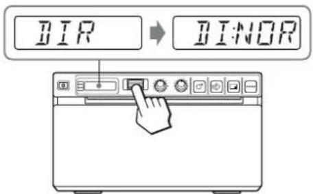
The unit enters the mode in which you can select the printing direction.
“DI:NOR,” which is the factory setting, is displayed on the LCD. “DI:NOR” is the currently selected setting.
In this menu operation, you will change the setting to "DI:REV."
5 Display "DI:REV" in the LCD by turning the jog dial up or down, and then press the jog dial.
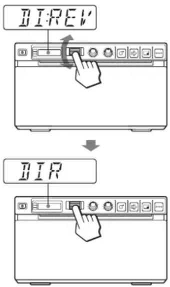
“DI:REV” is registered as the printing direction.
Note
If about 20 seconds elapse without making any menu operation after you have displayed the menu item or setting, the display returns to “READY” on the LCD and the unit exits the menu mode. In such a case, the setting of “DIR” is not changed.
To cancel the setting
1 Display "BACK" by turning the jog dial in step 5.
2 Press the jog dial.
The display on the LCD returns to “DIR.”
To continue menu operations
Make settings by repeating steps 3 to 5.
To end the menu operation
1 Display "BACK" by turning the jog dial after performing the operation of step 5.
2 Press the jog dial.
The display returns to “READY.”
The unit exits the menu mode.
Menu lock function
If the message “LOCK” is displayed and you hear the alarm sound when you press the jog dial, the jog dial is disabled because the menu operation function is locked. If you want to perform a menu operation, contact the nearest authorized dealer.
Registering Menu Settings
You can store up to three sets of settings made using the menu, and you can load the desired setting when needed. The unit retains these settings even if you turn off the power.
Note
When you use the unit for the first time after you purchase it, factory settings are registered in all three of the stored selections.
Registering new settings
1 Make all of the required settings.
2 Display "SAVE" by turning the jog dial, and then press the jog dial.
3 Display the desired number by turning the jog dial, and then press the jog dial, again. The settings made in step 1 are registered in the number selected in step 3.
Loading the desired settings
You can load the desired settings and make printouts with the loaded settings.
1 Confirm that "READY" is displayed on the LCD, and press the jog dial.
2 Display "LOAD" by turning the jog dial, and then press the jog dial again.
3 Display the number corresponding to the desired settings, and then press the jog dial.
Settings corresponding to the number selected in step 3 are loaded.
When you change the loaded settings
The unit operates according to the changed settings. In this case, the unit operates according to these settings until you load another set of settings, even if you turn off the unit. When you load another group of settings, the settings loaded previously are cleared.
To retain previously loaded settings
Example: Settings registered as “SA:1” are loaded and settings are to be changed. To retain the original settings of “SA:1” and to register the new settings as “SA:2,” proceed as follows.
1 Load the settings of "LO:1" following the procedure for loading the desired settings.
2 Change the loaded settings as required.
3 Select "SA:2" following procedure for registering the settings.
4 Press the jog dial.
The settings, changed in step 2, are registered as “SA:2” (No.2).
Printing the Menu List
You can make a printout of the current menu settings.
1 Press the jog dial.
The menu item you changed last is displayed.
2 Display "MENU" by turning the jog dial, and then press the jog dial.
3 Display "ME:OK" by turning the jog dial and then press the jog dial.
The unit starts printing the current menu settings.
"MENU" is displayed on the LCD.
4 Display "BACK" by turning the jog dial, and then press the jog dial.
The message "READY" is displayed on the LCD, and the unit returns to the normal printing mode.
Printing
Before Starting a Print Job
Always check the following points:
- unit connected correctly? (page 42)
• Paper loaded correctly? (page 43) - Menu settings and menu adjustments done correctly? (page 45)
• Video source being input? (page 42)
Starting a Print Job
You can set up the printing direction, image size, all sorts of settings for printing, using the menu. This section describes operations after completing all sorts of settings using the menu.
1 Press the power ON/OFF switch to turn the unit on. The back light on the LCD lights in green, and "READY" is displayed on the LCD.

2 Start the video source.
This operation is done using the controls of the video equipment which you are using as a source.
3 Press the PRINT button when the image you want to print is on the video monitor.
The image displayed at the instant you press the PRINT button is captured into memory and is printed out immediately. Up to 10 captured images are stored in memory. When captured image exceeds 10, the oldest data is overwritten with the latest one in sequence.
When the message is displayed on the LCD
If a problem occurs, the back light on the LCD lights in umber and the error message stating the problem is displayed on the LCD.
Message Cause and remedy
EMPTY Paper is not loaded. Load paper.
DOOR The door is open. Close the door.
When the unit stops printing during printing
When printing almost black images continuously, the thermal head protection circuit may shut down the unit to prevent the thermal head from overheating. In such a case, the message “COOL” is displayed on the LCD. Leave the unit until the head cools down and this message disappears.
To cancel a print job in progress
To cancel a print job in progress, press the OPEN button or the FEED button.
To feed paper
To feed paper, press the FEED button. The unit will continue to feed paper as long as you hold down the FEED button. Do not attempt to pull paper out of the unit with your hand.
Paper currently selected
You can confirm the paper currently selected on the LCD. The pointer points to the paper currently selected. In the following figure, the currently selected paper is the UPP-110S paper.
If the printout image is blurred
A rapidly moving image may be blurred when printed. Should this occur, make a printout with “ME:FLD” selected in the “MEMRY” menu item.
Printing images stored in memory
Each time you press the PRINT button, the image is stored in memory. After 10 images have been stored, the oldest image data is overwritten with the newest captured image in sequence. There are always 10 images stored in memory. You can load the desired one from among them and print it using the menu.
1 Select "PAGE" from among the menu items.
For detailed information on menu operation, see "Basic Menu Operations" on page 49.
2 Press the jog dial.
“PG:1” is displayed on the LCD, and the image printed last is displayed on the monitor. As the number increases, the image displayed becomes older.
3 Display the image that you want to print by turning the jog dial up or down.
4 Press the jog dial.
The image selected in step 3 is loaded.
5 Press the COPY button.
The image selected in step 3 is printed.
Printing two different images on one sheet
“MU:MLT” selected in the “MULTI” menu item allows you to capture two different images and print them on one sheet.
1 Select "MU:MLT" in the "MULTI" menu item.
2 Press the PRINT button in step 3, following the operations outlined in "Starting a Print Job" on page 51.
The image displayed at the instant you press the PRINT button is captured.
3 Press the PRINT button again when the image you want to print is on the video monitor.
The printer start printing two images on one sheet as follows.
Image captured in step 2
Image captured in step 3
When "IF:ON" is selected in "INFO," data on the contrast and brightness of the image captured in step 3 is printed under the image.
Making Copies of the Last Printout
Press the COPY button. The unit makes a copy of the last printout. The image of the last printout is retained in the unit's memory until you make a printout of another image or turn the power off. You can make only one copy regardless of the print quantity set using the menu.
Notes
- If you press the COPY button immediately after turning the power on, the alarm buzzer will sound as nothing is stored in memory.
- Turning off the power of the printer will cause the image stored in memory to be lost.
To make multiple copies of the same printout
Press the COPY button as many times as necessary (maximum 20 copies including the first printout) while copying the first printout. Each time you press the COPY button, a short buzzer sounds.
Note
The number of printouts printed by pressing the PRINT button is also included in the maximum number. For example, If you press the COPY button after you pressed the PRINT button five times and made five printouts, the number of multiple copies of the same printout becomes 15.
To interrupt copying
Press the OPEN or FEED button while copying.
To make copies in different directions and sizes
You can copy the image stored last in a different direction and size. Before pressing the COPY button, select the printing direction and size.
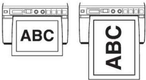
Selecting the Printing Direction and Image Size
You can select the printing direction and image size using the following menu items.
“SIDE”: Selects the direction in which the image is to be printed.
“SCALE”: Enlarges or reduces the size of the image to be printed.
SFT.H and SFT.V: Sets the printing range vertically and horizontally.
Selecting the printing direction
You can select the printing direction using the "SIDE" menu item.
To print in the same direction as the one displayed on the video monitor
Select "S:STD" from "SIDE."
To print the image rotated by 90 degree counterclockwise
Select "S:SIDE" from "SIDE."
Image displayed on the video monitor

Printouts
When "S:STD" is selected
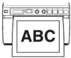
When "S:SIDE" is selected
Selecting the image size
The “SCALE” menu item allows you to enlarge or reduce the size of the image. You can set the image size from half the normal size of the image up to two times the size of the image in 0.1 step increments.
To set the range of the image to be printed
You can set the printing range vertically and horizontally using "SFT.V" and "SFT.H" menu items.
You can set the range while watching the image displayed on the monitor.
The frame displayed on the monitor moves according to the value being changed using the jog dial. The image within the frame is printed.
Example: "S:STD" selected from "SIDE" and "SCL:2.0" selected from "SCALE"
Original image
Images on the monitor
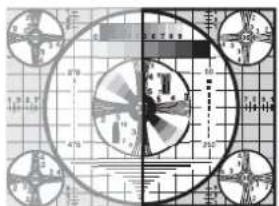
Printouts
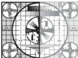
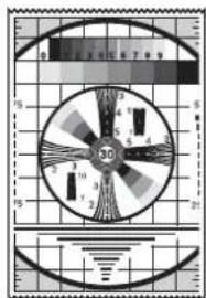
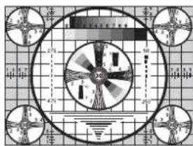
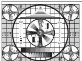
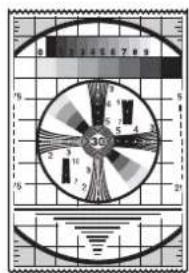
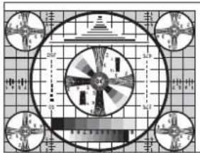
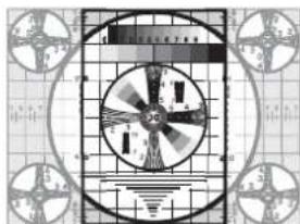
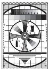
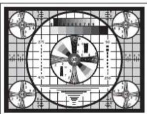
When "S.H:+(*)" is selected

When "S.H:0" is selected
natural_image
Technical diagram of a fan or impeller assembly with grid background and four circular components (no text or symbols)
When "S.H:-(*)" is selected
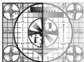
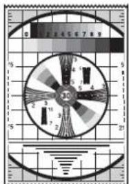
Difference of the size of the printout depending on the setting of "SCALE"
When "S:STD" is selected from "SIDE" and "SCL:2.0" is selected from "SCALE"
When "S: STD" is selected from "SIDE" and "SCL:1.0" is selected from "SCALE"
The length is two times longer than the length when "SCL:1.0" is selected.
Adjusting the Contrast and Brightness
You can adjust the contrast and brightness of the unit using the CONTR control and BRIGHT control on the front panel.
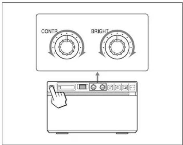
To adjust the contrast
You can adjust the contrast of printouts using the CONTR control.
To make the contrast stronger: Turn the CONTR control clockwise.
To make the contrast weaker: Turn the CONTR control counterclockwise.
To adjust the brightness
You can adjust the brightness of printouts using the BRIGHT control.
To make the image brighter: Turn the BRIGHT control clockwise.
To make the image darker: Turn the BRIGHT control counterclockwise.
Note
When the menu operation function is locked, CONTR and BRIGHT controls are also disabled in addition to the jog dial. If you want to use the CONTR and BRIGHT controls, contact the nearest authorized dealer.

Others
Precautions
On Safety
- Check the operating voltage before operation. Operate the unit only with a power source specified in "Specifications".
- Stop operation immediately if any liquid or solid object falls into the cabinet. Unplug the unit and have it checked by qualified personnel.
- Unplug the unit from the wall outlet if you will not be using it for a long time. Disconnect the power cord by grasping the plug. Never pull the cord itself.
- Do not disassemble the cabinet. Refer servicing to qualified personnel only.
- Connect the power plug of the unit to a wall outlet with a protective earth terminal. The safety earth should be properly established.
Caution on the paper cutter
A paper cutter is mounted with the unit. When loading a paper or cleaning the unit, be careful not to touch the paper cutter. Touching the paper cutter may cause injury.
On the Printer Carriage
Do not carry or move the unit when the paper roll is placed in the unit. Doing so may cause a malfunction.
On Installation
- Place the unit on a level and stable surface. If you use the unit with placed on an uneven surface, malfunction of the unit is likely to occur.
- Do not install the unit near heat sources. Avoid locations near radiators or air ducts, or places subject to direct sunlight or excessive dust, humidity, mechanical shock or vibration.
- Provide adequate air circulation to prevent heat build-up. Do not place the unit on surfaces such as rugs, blankets, etc., or near materials such as curtains and draperies.
• To prevent internal heat built-up, leave enough room around the printer for air to circulate through the
ventilation holes (intake) on the left hand side and the ventilation holes (exhaust) on the rear of the cabinet.
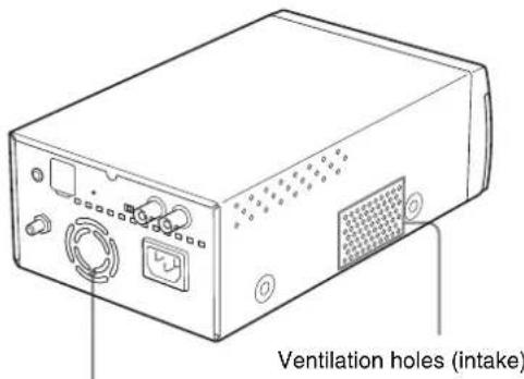
Ventilation holes (exhaust)
- If the unit is subjected to wide and sudden changes in temperature, such as when it is moved from a cold room to a warm room or when it is left in a room with a heater that tends to produce large amounts of moisture, condensation may form inside the unit. In such cases the unit will probably not work properly, and may even develop a fault if you persist in using it. If moisture or condensation forms, turn off the power and allow the unit to stand for at least one hour.
Maintenance
Cleaning the Cabinet
Use a wrung out damp cloth, or a damp cloth soaked in water and a mild detergent, to clean the cabinet surface. To avoid damaging the cabinet of the unit, never use alcohol, thinner, or any other type of organic solvent, or any type of abrasive cleaner, to clean the cabinet.
Cleaning the Thermal Head
If the printout is dirty or white stripes appear on the printouts, clean the thermal head using the cleaning sheet supplied.
Carry out the head cleaning operation using the menu.
Note
A paper cutter is mounted with the unit. When cleaning the thermal head, be careful not to touch the paper cutter. Touching the paper cutter may cause injury.
1 Press the power ON/OFF switch to ON to turn the unit on.

natural_image
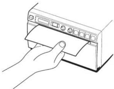
Line drawing of a kitchen appliance with a hand pointing to the front panel (no text or symbols)2 Press the OPEN button to open the door.
natural_image
Technical line drawing of a mechanical device with a downward arrow indicating motion or force (no text or symbols present)If the paper is loaded in the paper tray, remove it.
3 Insert the cleaning sheet, with the black surface facing down, into the groove of the paper tray.
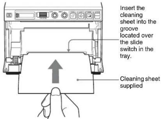
4 Close the door by pushing it.
5 Press the jog dial. The menu item changed last is displayed.
6 Display "CLEAN" by turning the jog dial, and then press the jog dial.
7 Confirm that "CL:OK" is displayed, and then press the jog dial. The unit starts cleaning the thermal head. "CLEAN" is displayed on the LCD. When the cleaning sheet stops and the alarm sounds, the cleaning is completed.
8 Press the OPEN button to open the door and remove the cleaning sheet.
9 Close the door by pushing it.
Note
Clean the thermal head only when necessary. If you clean the thermal head too frequently, it may cause a malfunction.
Cleaning the Platen Roller
When the surface of the platen roller gets dirty, paper will not be ejected smoothly after printing, resulting in paper jams and inconsistent print quality. Press the power ON/OFF switch to ON to turn the unit on, and then press the FEED button for a second or so to feed some more paper out of the unit. It is likely that the roller is getting dirty if paper is easily pulled out by hand.
natural_image
Line drawing of a hand inserting a card into a printer (no text or symbols)Clean the platen roller using a soft cloth moistened with ethyl alcohol when it becomes dirty.
1 Press the power ON/OFF switch to ON to turn the unit on.
2 Press the OPEN button to open the door.
If the paper is loaded in the paper tray, remove it.
3 Clean the platen roller gently using a soft cloth moistened with ethyl alcohol.
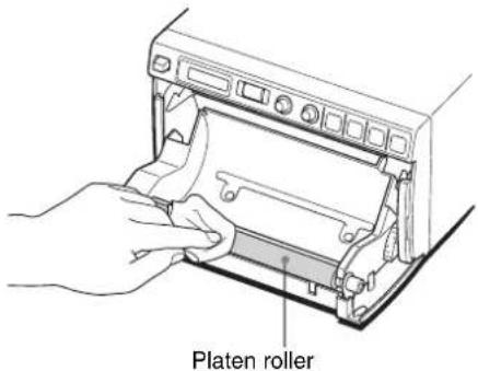
Notes
• After the surface of the platen roller wiped has been dried completely, turn the platen roller to clean another portion.
- Do not turn the platen roller with hands. Use the FEED button to turn it. To clean another part of the surface of the platen roller, go to the next step.
4
Press and hold down the FEED button so that the platen roller turns automatically. Release the FEED button when the surface of the platen roller to be cleaned appears.
natural_image
Technical line drawing of a mechanical device with a hand pressing a button (no text or symbols)Be careful so that you have your fingers caught in the turning platen roller.
Notes
• The platen roller is turning while you are pressing the FEED button. Be careful so that you have your fingers caught in the turning platen roller.
- Be sure to start cleaning only after the platen roller has stopped completely.
5
Repeat steps 3 and 4 until the platen roller becomes clean.
6
After the platen roller has been dried completely, close the door by pushing it.
Specifications
Power requirement
100 to 240 VAC, 50/60 Hz
Input current 1.5 A to 0.8 A
Operating temperature
5^ to 35^ (41 °F to 95 °F)
Operating humidity
20% to 80%
Operating pressure
700 hPa to 1,060 hPa
Storage and transport temperature
-20^ to +60^ (-4^ to +140^)
Storage and transport humidity
20% to 80%
Storage and transport pressure
700 hPa to 1,060 hPa
Dimensions 154 × 88 × 240 mm (w/h/d)
(6 1/6 × 3 1/2 × 9 1/2 inches)
Mass 2.6 kg (5 lb 11 oz) (printer only)
Thermal head Thin-film thermal head, 1280 dots
Gradation 256-level gradation (8-bit)
Resolution (when "SC:WD1" is selected from "SCAN")
EIA: 1210 × 490 dots
CCIR: 1210 × 582 dots
Picture size (when "SC:WD1" or "SC:NOR" is selected
from "SCAN")
When "S:STD" is selected from
"SIDE"
EIA: 94 × 73 mm
CCIR: 94 × 71 mm
When "S:SIDE" is selected from
"SIDE"
EIA: 124 × 96 mm
CCIR: 127 × 96 mm
Printing speed About 2 sec./image (at standard
setting) (when "SP:HI" is selected
from "SPEED")
About 3.3 sec./image (at standard
setting) (when "SP:NOR" is
selected from "SPEED")
Picture memory 10 frames (800 k × 8 bits for one frame)
Input connector VIDEO IN (BNC type)
EIA or CCIR composite video signals
1.0 Vp-p, 75 ohms/high-impedance
(EIA/CCIR automatically
discriminated)
Output connector
VIDEO OUT (BNC type)
EIA or CCIR composite video signals
1.0 Vp-p, 75 ohm loop-through/EE
switchable
REMOTE connector (stereo mini jack)
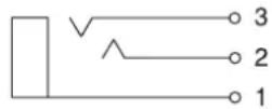
1 GND
2 PRINT SIGNAL (TTL)
Input of LOW pulse over 100 msec. initiates print.
3 PRINT BUSY (TTL)
Goes HIGH during printing
Accessories provided
Thermal head cleaning sheet (1)
Media label (1)
Operating Instructions (1)
Service Contact List (1)
Medical Specifications
Protection against electric shock:
Class I
Protection against harmful ingress of
water:
Ordinary
Degree of safety in the presence of a flammable anesthetic mixture with air or with oxygen or nitrous oxide: Not suitable for use in the presence of a flammable anesthetic mixture with air or with oxygen or nitrous oxide
Mode of operation:
Continuous
The design and these specifications are subject to change without prior notification.
Notes
- Always verify that the unit is operating properly before use.
SONY WILL NOT BE LIABLE FOR DAMAGES OF ANY KIND INCLUDING, BUT NOT LIMITED TO, COMPENSATION OR REIMBURSEMENT ON ACCOUNT OF FAILURE TO PRINT CONTENT OF ANY TYPE OR LOSS OF DATA DUE TO FAILURE OF THIS UNIT OR ITS PRINTING MEDIA, ASSOCIATED SOFTWARE, EXTERNAL STORAGE, OR OTHER EXTERNAL DEVICE.
- SONY WILL NOT BE LIABLE FOR DAMAGES OF ANY KIND INCLUDING, BUT NOT LIMITED TO, COMPENSATION OR REIMBURSEMENT ON ACCOUNT OF THE LOSS OF PRESENT OR PROSPECTIVE PROFITS DUE TO FAILURE OF THIS UNIT, EITHER DURING THE WARRANTY PERIOD OR AFTER EXPIRATION OF THE WARRANTY, OR FOR ANY OTHER REASON WHATSOEVER.
Troubleshooting
Before you call for service, please check the problems and solutions described below. If you cannot solve the problem, contact the nearest authorized dealer.
| Symptom Causes/remedies | |
| First few prints spotted with small dots. | New paper roll just installed?→If a new roll of paper has just been loaded, paper dust may cause white spots in printed images. Press the FEED button and hold it down to feed about 15~20 cm (6~8 in.) and then release.(page 43) |
| Print job does not start. | Paper does not feed.→Power switched on?→Unit connected correctly?(page 42)→Paper roll loose? (page 43)→“MU:MLT” selected from the “MULTI” menu item? (page 47)Alarm sounds.→Paper loaded correctly?(page 43)→Has the thermal head overheated? The thermal head may overheat when the unit prints dark image continuously. Wait until the head cools down.→Is the video signal of the image input? (page 42)Paper feeds but printing does not start.→Paper loaded with the wrong side up? (page 43) |
| Black borders or missing portions around the printout | This problem may result from the video signal input to the unit.→Change the setting of the “SCAN” menu item. (page 47) |
| Paper Jams • Jammed paper visible?→Press the OPEN button to open the paper door, remove the printout or the paper roll, and then gently pull the jammed paper out of the unit.Condensation collected in unit?→If the unit has just been brought into a warm room from a cold location, condensation may have formed inside the unit. Switch the unit off and let it set for 1 - 2 hours (until it warms to room temperature), then try printing again. | |
| Printouts dirty. • Thermal head dirty?→Use the head cleaning sheet provided with the unit to clean the thermal head. (page 57)Platen roller dirty?→Clean the platen roller using a soft cloth moistened with ethyl alcohol. (page 58) | |
| Symptom Causes/remedies | |
| Paper is not fed smoothly. | Platen roller dirty?→Clean the platen roller. (page 58) |
| The unit stops printing while printing almost black images and the message “COOL” is displayed on the LCD. | When printing almost black images continuously, the thermal head protection circuit may shut down the unit to prevent the thermal head from overheating.→Stop printing and allow the thermal head to cool. |
| White lines or small letters on the screen are not printed clearly. | Is “CO:ON” selected in the “COLOR” menu item for black and white input signals?→Select “CO:OFF” in “COLOR” when the input signal is a black and white signal. (page 46) |
| Small squares appear over the whole screen. | Is “CO:OFF” selected in the “COLOR” menu item for color input signals?Select “CO:ON” in “COLOR” when the input signal is a color signal. (page 46) |
| The printout is too dark or too light. | I s t h e 7 5 Ω select switch set correctly? (page 42)Is the “MEDIA” menu item set correctly? (page 47)Is the “GAMMA” menu item set correctly? (page 46) |
| The printout seems stretched or enlarged. | Is “AS:1:1” selected in the “ASPCT” menu item?→Select “AS:4:3.” (page 46) |
Error Messages
Messages appear on the LCD under the following conditions. Take the remedial actions shown next to the messages to correct the problem.
| Messages Description and remedy |
| DOOR The paper door is open.→Close the paper door until it is locked securely. |
| EMPTY • There is no paper loaded.• Paper has been used up.→Load some paper. (page 43) |
| COOL The protection circuit that prevents the thermal head from overheating has been activated.→Wait for the message to disappear.Printing will then resume automatically. |
| LOCK The menu operation function is locked.The jog dial, CONTR control and BRIGHT control are disabled.→If you want to perform menu operations or use those controls, contact the nearest authorized dealer. |


Index
C
Connections 42
E
Error messages 61
G
Getting Started 40
L
Location and function of parts and controls front panel 40 rear panel 41
M
Maintenance
cleaning the cabinet 57 cleaning the platen roller 58 cleaning the thermal head 57
Menu
basic operations 49 list 46 loading the menu settings 50 menu flow 45 printing the menu list 51 storing the menu settings 50
0
Overview 40
P
Paper
loading 43 notes on storing and handling 42 paper you can use 42
Precautions
on installation 56 paper cutter 56 printer carriage 56 safety 56
Printing
adjusting the brightness 54 adjusting the contrast 54 cancelling 52 staring a print job 51
s
Specifications 59
T
Troubleshooting 60

index
AVERTISSEMENT
Papiers Supportés 72
natural_image
Line drawing of a kitchen appliance with a hand pointing to the front panel (no text or symbols)natural_image
Technical line drawing of a mechanical device with a downward arrow indicating motion (no text or symbols)natural_image
Diagram of a printer printing a sheet of paper with arrows indicating motion (no text or symbols)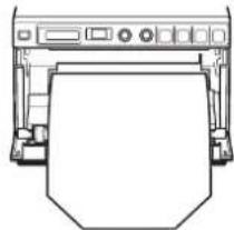
natural_image
Line drawing of a printer with paper cutout (no text or symbols)natural_image
Diagram showing three different types of household appliances: a hand pressing down a printer, two crossed-out devices, and one crossed-out device (no text or symbols present)Remarques
natural_image
Illustration of a hand pressing a button on a computer monitor (no text or symbols visible)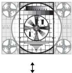
natural_image
Diagram of a fan or vent with radial blades and grid pattern, no readable text or symbols
natural_image
Line drawing of a kitchen appliance with a hand pointing to the front panel (no text or symbols)natural_image
Line drawing of a printer or printer with a paper roll being inserted, showing no text or symbols.natural_image
Line drawing of a hand inserting a card into a printer (no text or symbols)natural_image
Line drawing of a hand inserting a device into a rack (no text or symbols)Rouleau de plateau
Remarques
natural_image
Technical line drawing of a mechanical device with a hand pressing a button (no text or symbols)VIDEO OUT (type BNC)
natural_image
Line drawing of a hand pressing down on a wall-mounted appliance (no text or symbols)natural_image
Technical line drawing of a mechanical device with a downward arrow indicating motion or force (no text or symbols present)natural_image
Diagram of a printer printing a sheet of paper with arrows indicating motion (no text or symbols present)
natural_image
Line drawing of a printer with paper cutout (no text or symbols)natural_image
Illustration showing three different types of window or door frame designs: a hand pressing down, two crossed-out windows, and a circular outline (no text or symbols)Hinweise
flowchart
```mermaid
graph TD
    A["READY"] --> B["RGC"]
    B --> C["AS ON RGOFF BACK"]
    C --> D["AS 11 AS 43 BACK"]
    D --> E["NEOFF NE ON BACK"]
    E --> F["CL OK BACK"]
    B --> G["RSPCT"]
    G --> H["BEEP"]
    H --> I["CLEAN"]
    I --> J["COLOR"]
    J --> K["DIP"]
    K --> L["FEED"]
    L --> M["GRAMA"]
    M --> N["IMAGE"]
    N --> O["INFO"]
    O --> P["INTAT"]
    P --> Q["LOAD"]
    Q --> R["MEJIA"]
    R --> S["HEMRY"]
    S --> T["MENU"]
    T --> U["MULTI"]
    U --> V["PAGE"]
    V --> W["DIY"]
    W --> X["SAFE"]
    X --> Y["SCALE"]
    Y --> Z["SCAN"]
    Z --> AA["SF1H"]
    AA --> AB["SF1V"]
    AB --> AC["SHARP"]
    AC --> AD["SIZE"]
    AD --> AE["SPEEK"]
    AE --> AF["VINEO"]
    AF --> AG["BACK"]

    subgraph Process Steps
        B --> H
        H --> I
        I --> J
        J --> K
        K --> L
        L --> M
        M --> N
        N --> O
        O --> P
        P --> Q
        Q --> R
        R --> S
        S --> T
        T --> U
        U --> V
        V --> W
        W --> X
        X --> Y
        Y --> Z
        Z --> AA
        AA --> AB
        AB --> AC
        AC --> AD
        AD --> AE
        AE --> AF
        AF --> AG
    end

    %% Note: The diagram shows a hierarchical or hierarchical process with labeled steps and corresponding labels. The diagram is structured to compare the process of sequential steps (e.g., 'PG 10 PG 1 BACK', 'SH+(*) SH-0 SH-*) BACK') based on their specific steps. The structure implies a multi-step process with branching paths and label markers (e.g., 'LA 3 SA 2 SA 1' and 'SCL20' are not explicitly labeled). The diagram is designed to define the process itself. The output is presented in a CSV format with two columns: 'Step Number' and 'Back'. The entire diagram is labeled 'READ'. The arrows indicate direction of progression through each step. The text 'MUSGL BACK' is also present in the top right corner. The diagram is structured as follows: 'MOHLT MUSGL BACK' at the bottom right, 'SCL20' at the bottom center, and 'SH 14' at the bottom left. The diagram is designed to define the process sequence.


natural_image
Line drawing of a kitchen appliance with a hand pointing to the front panel (no text or symbols)natural_image
Line drawing of a printer or printer with a hand pressing down on the cover (no text or symbols present)natural_image
Line drawing of a hand inserting a card into a printer (no text or symbols)natural_image
Technical line drawing of a mechanical device with a hand pressing a button (no text or symbols)natural_image
Line drawing of a hand pressing down on a front panel (no text or symbols)natural_image
Technical line drawing of a mechanical device with a downward arrow indicating motion or force (no text or symbols present)natural_image
Diagram of a printer printing a sheet of paper with arrows indicating motion (no text or symbols)
natural_image
Line drawing of a printer with paper sheet and control panel (no text or symbols)natural_image
Illustration showing three window frames with a hand pointing at a printer screen (no text or symbols)Note


natural_image
Line drawing of a hand pressing down on a wall-mounted air conditioner unit (no text or symbols)natural_image
Diagram of a printer or printer with a downward arrow indicating compression or disassembly (no text or symbols present)natural_image
Line drawing of a hand inserting a card into a printer (no text or symbols)natural_image
Line drawing of a printer or printer with a hand cursor pointing to the screen (no text or symbols present)1 Conector REMOTE (166)
natural_image
Line drawing of a hand pressing down on a wall-mounted appliance (no text or symbols)natural_image
Diagram of a printer or printer with a paper roll being inserted, showing no text or symbols.natural_image
Diagram of a printer printing a sheet of paper with directional arrows indicating motion (no text or symbols)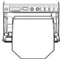
natural_image
Line drawing of a printer with paper sheet and control panel (no text or symbols)natural_image
Diagram showing three window frame configurations: a printer, a washing machine, and a circular device with cross marks (no text or symbols)Notas
Si se selecciona DI:NOR Si se selecciona DI: REV
Si se selecciona SC:NOR
Si se selecciona SC:WD1
Si se selecciona SC:WD2

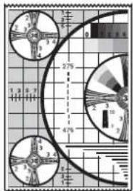
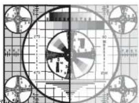
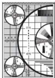
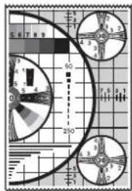
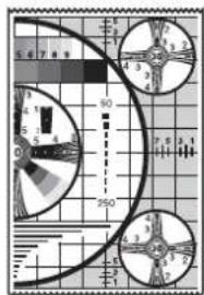
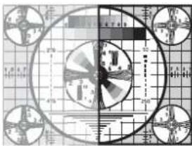
Si se selecciona "S.H:0"
natural_image
Technical diagram of a fan or impeller with geometric patterns and measurement scale (no text or labels)
Si se selecciona "S.H:-(*)"
natural_image
Line drawing of a hand pressing down on a wall-mounted air conditioner unit (no text or symbols)natural_image
Diagram of a printer or printer holder with a downward arrow indicating compression or disassembly (no text or symbols present)natural_image
Line drawing of a hand inserting a card into a printer (no text or symbols)natural_image
Line drawing of a printer with a hand pressing a button (no text or symbols)CISPR11, Class B, Group 1 표준에 따름)
제품에 사용된 기호
natural_image
Line drawing of a kitchen appliance with a hand pointing to the front panel (no text or symbols)natural_image
Diagram of a printer or printer with a paper roll being inserted, showing no text or symbols.natural_image
Illustration of a printer emitting paper with arrows indicating motion (no text or symbols)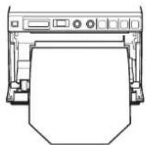
natural_image
Line drawing of a printer with paper cutout (no text or symbols)natural_image
Line drawing of a hand pressing down on a paper sheet (no text or symbols)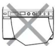
참고
flowchart
graph TD
    A["REACH"] --> B["REG"]
    B --> C["ASPT"]
    C --> D["DEEP"]
    D --> E["CLAM"]
    E --> F["COLOR"]
    F --> G["BIP"]
    G --> H["FEEN"]
    H --> I["GRAMM"]
    I --> J["IMAGE"]
    J --> K["INFO"]
    K --> L["INITAT"]
    L --> M["LOAD"]
    M --> N["MEDIA"]
    N --> O["MEHRY"]
    O --> P["MENU"]
    P --> Q["MULTI"]
    Q --> R["PAGE"]
    R --> S["QTY"]
    S --> T["SAVE"]
    T --> U["SCALE"]
    U --> V["SCAN"]
    V --> W["SFTH"]
    W --> X["SFIX"]
    X --> Y["SHARP"]
    Y --> Z["SIDE"]
    Z --> AA["SPEED"]
    AA --> AB["VIDEO"]
    AB --> AC["BACK"]

    B -->|AG ON AGOFF BACK| AD["AS 11 AS 43 BACK"]
    D -->|DEOFF IE ON BACK| AE["CL OK BACK"]

    E -->|CO ON COFF BACK| AF["BIOP"]
    F -->|DIVE DHOR BACK| AG["FEE"]
    G -->|FEOFF FE ON BACK| AH["GA 4 GA 3 GA 2 GA 1 BACK"]

    J -->|IMNEG IMPOS BACK| AI["INFO"]
    AI --> AJ["INITAT"]
    AJ --> AK["LOAD"]
    AK --> AL["MEDIA"]
    AL --> AM["MEHRY"]
    AM --> AN["MENU"]
    AN --> AO["MULTI"]
    AO --> AP["PAGE"]
    AP --> AQ["QTY"]
    AQ --> AR["SAVE"]
    AR --> AS["SCALE"]
    AS --> AT["SCAN"]
    AT --> AU["SFTH"]
    AU --> AV["SFIX"]
    AV --> AW["SHARP"]

    R -->|PG 10 PG 1 BACK| AX["SPHOR BACK"]

    S -->|QT 9 QT 1 BACK| AY["SPHOR BACK"]

    T -->|SW+(*) SH-(*) BACK| AZ[SCHS/SCHS/SS/SS/SS/SS/SS/SS/SS/SS/SS/SS/SS/SS/SS/SS/SS/SS/SS/SS/SS/SS/SS/SS/SS/SS/SS/SS/SS/SS/SS/SS/SS/SS/SS/SS/SS/SS/SS/SS/SS/SS/SS/SS/SS/SS/SS/SS/SS/SS/SS/SS/LL/LL/LL/LL/LL/LL/LL/LL/LL/LL/LL/LL/LL/LL/LL/LL/LL/LL/LL/LL/LL/LL/LL/LL/LL/LL/LL/LL/LL/LL/LL/LL/LL/LL/LL/LL/LL/LL/LL/LL/LL/LL/LL/LL/LL/LL/LL/LL/LL/LL/ LL/LL/LL/LL/LL/LL/LL/LL/LL/LL/LL/LL/LL/LL/LL/LL/LL/LL/LL/LL/LL/LL/LL/LL/LL/LL/LL/LL/LL/LL/LL/LL/LL/LL/LL/LL/LL/LL/LL / LL / LL / LL / LL / LL / LL / LL / LL / LL / LL / LL / LL / LL / LL / LL / LL / LL / LL / LL / LL / LL / LL / LL / LL / LL / LL / LL / LL / LL / LL / LL / LL / LL / LL / LL / LL / LL / LL / LL / LL / LL / LL / LL / LL / LL / LL / LL / LL / LL / LL / LLC / LLC / LLC / LLC / LLC / LLC / LLC / LLC / LLC / LLC / LLC / LLC / LLC / LLC / LLC / LLC / LLC / LLC / LLC / LLC / LLC / LLC / LLC / LLC / LLC / LLC / LLC / LLC / LLC / LLC / LLC / LLC / LLC / LLC / LLC / LLC / LLC / LLC / LLC / LLC / LLC / LLC / LLC / LLC / LLC / LLC / LLC / LLC / LLC / LLC /
AS:4:3을 선택한 경우
AS:1:1을 선택한 경우
b)인쇄 방향은 다음과 같습니다.
SC:WD1을 선택한 경우
SC:WD2 를 선택한 경우

작업
모니터의 이미지 인쇄물
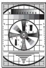
"S.H:+(*)"를 선택한 경우

"S.H:0"을 선택한 경우
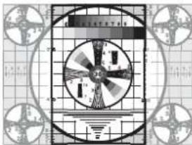

"S.H:-(*)"를 선택한 경우