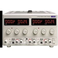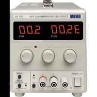
EX355P - Battery charger Aim TTi - Free user manual and instructions
Find the device manual for free EX355P Aim TTi in PDF.


User questions about EX355P Aim TTi
0 question about this device. Answer the ones you know or ask your own.
Ask a new question about this device
Download the instructions for your Battery charger in PDF format for free! Find your manual EX355P - Aim TTi and take your electronic device back in hand. On this page are published all the documents necessary for the use of your device. EX355P by Aim TTi.
USER MANUAL EX355P Aim TTi
text_image
Aim T T iAIM & THURLBY THANDAR INSTRUMENTS
EX355P
Programmable Bench Power Supply
INSTRUCTION MANUAL
Aim-TTi
Table of Contents
Introduction 2
Specification 3
Safety 5
Installation 6
Connections 6
Operation 7
Remote Operation 8
Remote Commands 9
Maintenance 12
Instructions en Francais 13
The EX355P is a digitally controlled version of the EX355 with an isolated RS-232 interface. Using mixed-mode regulation technology it provides 0 to 35V at 0 to 5A in a compact and lightweight unit.
The EX355P offers a low-cost solution for a basic programmable PSU, and will be sufficient for many applications where the sophistication and complexity of GPIB is not needed.
A simple command set allows remote control of voltage, current and output-enable together with read-back of metering values and operational status.
Local control is via three rotary encoders providing rapid and accurate setting of voltage and current for bench use.
Excellent line and load regulation are matched by low noise and good transient response. High power efficiency ensures that the unit remains cool without any fan noise.
The EX series has been designed to meet the stringent requirements of the latest relevant IEC standards for safety and EMC, including harmonics emissions. All outputs are intrinsically short circuit proof, and are protected against external voltages and reverse currents.
Specification
General specifications apply for the temperature range 5^ C to 40^ C. Accuracy specifications apply for the temperature range 18^ C to 28^ C after 1 hour warm-up with no load and calibration at 23^ C. Typical specifications are determined by design and are not guaranteed.
OUTPUT
| Voltage Range: | 0V to 35V minimum | ||||
| Current Range: | 0.01A to 5A minimum | ||||
| Voltage Setting: | By coarse and fine rotary encoders or RS-232 interface.Resolution 10mV. Setting accuracy 0.3% ± 20mV (for V >0.1V) | ||||
| Current Setting: | By single rotary encoder or RS-232 interface.Resolution 10mA. Setting accuracy 0.6% ± 20mA (for I >0.1A) | ||||
| Operating Mode: | Constant voltage (CV) or constant current (CC) with automatic cross-over. | ||||
| Output Switch: | Electronic. Preset voltage and current displayed when off. | ||||
| Output Terminals: | Universal 4mm safety binding posts on 19mm (0.75") pitch. | ||||
| Output Protection: | Output will withstand up to 40V forward voltage.Reverse protection by diode clamp for reverse currents up to 3A. | ||||
| Load Regulation: | <0.01% of maximum output for a 90% load change. | ||||
| Line Regulation: | <0.01% of maximum output for a 10% line change | ||||
| Ripple & Noise(20MHz bandwidth): | Typically <2mVrms, <10mV pk-pk, constant voltage mode. | ||||
| Transient Response: | <200μs to within 50mV of set level for a 5% to 95% load change. | ||||
| Voltage Programming speed: | Maximum time required for the output to settle within 1% of its total excursion (for a resistive load). Excludes command processing time. | ||||
| 90% load | No load | 90% load | No load | ||
| Up | 210ms | 110ms | Down | 1.8s | |
| Temperature Coefficient: | Typically <100ppm/°C | ||||
| Status Indication: | Output on lamp. CC mode lamp. | ||||
METER SPECIFICATIONS
| Meter Types: | Separate 4 digit meter for voltage and 3 digit meter for current with 14mm (0.56") LED displays. Reading rate 4/sec. |
| Meter Resolutions: 100mV, 10mA | |
| Note that in constant voltage mode the meter will show the set voltage to resolution of 10mV. However, the metering resolution is limited to 100mV and when in CC mode the last digit will be set to zero. | |
| Meter Accuracies: | Voltage (CC mode) 0.3% ± 100mV.Current (CV mode) 0.6% ± 20mA |
MEMORY
The power supply saves the voltage, current and output-enable status at power down and restores the settings at power up.
RS-232 CONTROL
| Interface: | RS-232 interface, fully opto-isolated from power supply output.9-pin D connector. |
| Baud Rate: | Variable from 600 baud to 9,600 baud. |
| Remote Functions: Set voltage, Set Current, Set Output On/Off, Read Voltage, Read Current, Read On/Off, Read Mode (CV or CC). | |
| Setting Accuracy: | Voltage 0.3% ± 20mV (for V >0.1V).Current 0.6% ± 20mA (for I >0.1A). |
| Setting Resolution: | Voltage 10mV. Current 10mA. |
| Readback Accuracy: | Voltage 0.3% ± 100mV. Current 0.6% ± 20mA. |
| Readback Resolution: | Voltage 100mV. Current 10mA. |
| Remote command processing time: | Typically <10ms between receiving the command terminator for a step voltage change at the instrument and the output voltage beginning to change. |
GENERAL
| AC Input: | 220V-240V AC ± 10%, 50/60Hz.110V-240V AC ± 10% by factory option.Installation Category II. |
| Power Consumption: | 400VA max. |
| Operating Range: | +5°C to +40°C, 20% to 80% RH. |
| Storage Range: | -40°C to +70°C. |
| Environmental: | Indoor use at altitudes up to 2000m, Pollution Degree 2. |
| Safety & EMC: | Complies with EN61010-1 & EN61326-1.For details, request the EU Declaration of Conformity for this instrument via http://www.aimtti.com/support (serial no. needed). |
| Size: | 140 x 160 x 295mm (WxHxD). |
| Weight: | 2.8 kg |
Safety
This power supply is a Safety Class I instrument according to IEC classification and has been designed to meet the requirements of EN61010-1 (Safety Requirements for Electrical Equipment for Measurement, Control and Laboratory Use). It is an Installation Category II instrument intended for operation from a normal single phase supply.
This instrument has been tested in accordance with EN61010-1 and has been supplied in a safe condition. This instruction manual contains some information and warnings which have to be followed by the user to ensure safe operation and to retain the instrument in a safe condition.
This instrument has been designed for indoor use in a Pollution Degree 2 environment in the temperature range 5°C to 40°C, 20% - 80% RH (non-condensing). It may occasionally be subjected to temperatures between +5° and -10°C without degradation of its safety. Do not operate while condensation is present.
Use of this instrument in a manner not specified by these instructions may impair the safety protection provided. Do not operate the instrument outside its rated supply voltages or environmental range.
WARNING! THIS INSTRUMENT MUST BE EARTHED
Any interruption of the mains earth conductor inside or outside the instrument will make the instrument dangerous. Intentional interruption is prohibited. The protective action must not be negated by the use of an extension cord without a protective conductor.
When the instrument is connected to its supply, terminals may be live and opening the covers or removal of parts (except those to which access can be gained by hand) is likely to expose live parts. The apparatus shall be disconnected from all voltage sources before it is opened for any adjustment, replacement, maintenance or repair. Capacitors inside the power supply may still be charged even if the power supply has been disconnected from all voltage sources but will be safely discharged about 10 minutes after switching off power.
Any adjustment, maintenance and repair of the opened instrument under voltage shall be avoided as far as possible and, if inevitable, shall be carried out only by a skilled person who is aware of the hazard involved.
If the instrument is clearly defective, has been subject to mechanical damage, excessive moisture or chemical corrosion the safety protection may be impaired and the apparatus should be withdrawn from use and returned for checking and repair.
Make sure that only fuses with the required rated current and of the specified type are used for replacement. The use of makeshift fuses and the short-circuiting of fuse holders is prohibited.
Do not wet the instrument when cleaning it.
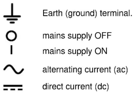
The following symbols are used on the instrument and in this manual:-
text_image
⊥ ○ | ~ =- Earth (ground) terminal. mains supply OFF mains supply ON alternating current (ac) direct current (dc)Installation
Mains Operating Voltage
Check that the instrument operating voltage marked on the rear panel is suitable for the local supply.
Mains Lead
When a three core mains lead with bare ends is provided this should be connected as follows:
BROWN - MAINS LIVE
BLUE - MAINS NEUTRAL
When fitting a fused plug a 5 amp fuse should be fitted inside the plug. As the colours of the wires in the mains lead of this apparatus may not correspond with the coloured markings identifying the terminals in your plug proceed as follows:
The wire which is coloured green-and-yellow must be connected to the terminal in the plug which is marked by the letter E or by the safety earth symbol shown above or coloured green or green-and-yellow.
The wire which is coloured blue must be connected to the terminal which is marked with the letter N or coloured black.
The wire which is coloured brown must be connected to the terminal which is marked with the letter L or coloured red.
WARNING! THIS INSTRUMENT MUST BE EARTHED.
Any interruption of the mains earth conductor inside or outside the instrument will make the instrument dangerous. Intentional interruption is prohibited.
Connections
Output Terminals
All power connections are made from the front panel.
The load should be connected to the positive (red) and negative (black) terminals marked OUTPUT. Both are fully floating and either can be connected to ground.
The terminal marked 12 is connected to the chassis and safety earth ground.
RS232
9-pin D-connector for PC remote control with the following connections:
Pin Name Description
| 1 | DCD | Linked to pins 4 and 6 |
| 2 | TXD | Transmitted data from instrument |
| 3 | RXD | Received data to instrument |
| 4 | DTR | Linked to pins 1 and 6 |
| 5 | GND | Signal ground |
| 6 | DSR | Linked to pins 1 and 4 |
| 7 | RTS | Linked to pin 8 |
| 8 | CTS | Linked to pin 7 |
| 9 | - | No internal connection |
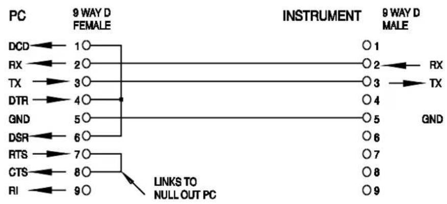
Connect to a PC with a cable which has pins 2, 3 and 5 wired plus pins 1, 4 & 6 and pins 7 & 8 linked at the PC end.
Operation
Setting Up the Output
With the POWER switch on (I) and the output off the output voltage and current limit can be accurately preset using the VOLTAGE and CURRENT controls; the left-hand meter shows the set voltage and the right-hand meter shows the set maximum current.
When the □output switch is switched on, the ON lamp lights; the left-hand meter still shows the preset voltage but the right-hand meter now shows the actual load current.
Constant Voltage
The output voltage is adjusted using the coarse and fine VOLTAGE controls; the coarse control changes the voltage in 100mV steps and the fine control in 10mV steps. The CURRENT control sets the maximum current that can be supplied; the control changes the current in 10mA steps.
Constant Current
If the load resistance is low enough such that, at the output voltage set, a current greater than the current limit setting would flow, the power supply will automatically move into constant current operation. The current output is adjusted by the CURRENT control and the VOLTAGE controls set the maximum voltage that can be generated.
The CC lamp lights to show constant current mode.
Instantaneous Current Output
The current limit control can be set to limit the continuous output current to levels down to 10mA. However, in common with all precision bench power supplies, a capacitor is connected across the output to maintain stability and good transient response. This capacitor charges to the output voltage and short-circuiting of the output will produce a current pulse as the capacitor discharges which is independent of the current limit setting.
Protection
The output has intrinsic short-circuit protection and is protected from reverse voltages by a diode; the continuous reverse current must not exceed 3 Amps, although transients can be much higher.
Connection to the Load
The load should be connected to the positive (red) and negative (black) output terminals. Both are fully floating and either can be connected to ground.
Series or Parallel Connection with Other Outputs
The outputs of the power supply are fully floating and may be used in series with other power supply units to generate high DC voltages up to 300V DC.
The maximum permissible voltage between any terminal and earth ground ( 12 ) is 300VDC.
WARNING! Such voltages are exceedingly hazardous and great care should be taken to shield the output terminals for such use. On no account should the output terminals be touched when the unit is switched on under such use. All connections to the terminals must be made with the power switched off on all units.
It should be noted that the unit can only source current and cannot sink it, thus units cannot be series connected in anti-phase.
The unit can be connected in parallel with others to produce higher currents. Where several units are connected in parallel, the output voltage will be equal to that of the unit with the highest output voltage setting until the current drawn exceeds its current limit setting, upon which the output will fall to that of the next highest setting, and so on. In constant current mode, units can be connected in parallel to provide a current equal to the sum of the current limit settings.
Note that the output terminals are rated at 15A maximum; if several outputs are operated in parallel to source higher currents than this the junction should be made at a separate point, not one of the terminals.
Ventilation
The power supply is very efficient but nevertheless can generate significant heat at full power. The supply relies on convection cooling only and it is therefore important that ventilation is never restricted if performance and safety are to be maintained.
Remote Operation
Remote command format and the remote commands themselves are detailed in the Remote Commands chapter.
Baud Rate Selection
The Baud rate is set by pressing the OPTION SELECT/OK button until bAUD appears in the left-hand display; the right-hand display shows the current setting in the form of 960 for 9600 Baud etc. Change the Baud rate by pressing the CHANGE button to step the rate through all the possible options. When the required rate is displayed press OPTION SELECT/OK again to confirm and exit the rate change mode.
Remote/Local Operation
At power on the instrument will be in the local state with the Rem (remote) lamp off. When a command is received the remote state will be entered and the Rem lamp will be turned on. The rotary controls are not locked out by this action and the instrument will be returned to the local state if they are used; however, if the instrument receives another character from the interface, the remote state will again be entered.
Local operation of the rotary controls, output On/Off switch and CHANGE button can be disabled by pressing the OPTION SELECT/OK button until LoCL appears in the left-hand display; the right-hand display shows the current setting, on or OFF. Alternate presses of the CHANGE button selects on or OFF; when the required setting is displayed press OPTION SELECT/OK again to confirm and exit the change mode.
Local operation can be restored at any time by pressing the OPTION SELECT/OK button; if LoCL has been set to OFF the first press of OPTION SELECT/OK returns the instrument to local control and subsequent presses select the other modes as described above.
RS232 Connector
The 9-way D-type serial interface connector is located on the instrument rear panel. The pin connections are as shown below:
Pin Name Description
| 1 | DCD | Linked to pins 4 and 6 | |
| 2 | TXD | Transmitted data from instrument | |
| 3 | RXD | Received data to instrument | |
| 4 | DTR | Linked to pins 1 and 6 | |
| 5 | GND | Signal ground | |
| 6 | DSR | Linked to pins 1 and 4 | |
| 7 | RTS | Linked to pin 8 | |
| 8 | CTS | Linked to pin 7 | |
| 9 | - | No internal connection | |
Connect to a PC with a cable which has pins 2, 3, 5, wired plus pins 1, 4, 6 and pins 7 and 8, linked at the PC end, see diagram.
flowchart
graph LR
    A["PC"] --> B["9 WAY D FEMALE"]
    B --> C["INSTRUMENT"]
    C --> D["9 WAY D MALE"]
    A --> E["DCD"] --> F["1○"]
    A --> G["RX"] --> H["2○"]
    A --> I["TX"] --> J["3○"]
    A --> K["DTR"] --> L["4○"]
    A --> M["GND"] --> N["5○"]
    A --> O["DSR"] --> P["6○"]
    A --> Q["RTS"] --> R["7○"]
    A --> S["CTS"] --> T["8○"]
    A --> U["RI"] --> V["9○"]
    W["LINKS TO NULL OUT PC"] --> X["0 1"]
    W --> Y["0 2"]
    W --> Z["0 3"]
    W --> AA["0 4"]
    W --> AB["0 5"]
    W --> AC["0 6"]
    W --> AD["0 7"]
    W --> AE["0 8"]
    W --> AF["0 9"]
Baud rate is set as described above; the other interface parameters are fixed as follows:
Start Bits: 1 Parity: None
Data Bits: 8 Stop Bits: 1
RS232 Character Set
Any ASCII code can be used. Bit 7 of ASCII codes is ignored, i.e. assumed to be low. No distinction is made between upper and lower case characters in command mnemonics and they may be freely mixed. The ASCII control codes between 00H and 31H are ignored, except for 0AH (Line Feed, LF) which is used as a command terminator.
Remote Commands
RS232 Remote Command Formats
The instrument's input buffer accepts a single command (or query) at a time, under interrupt, in a manner transparent to other instrument operations. Commands and queries must be sent as specified in the command list and must be terminated with the command terminator code 0AH (Line Feed, LF). Note that parameters are separated from the command header by one space (20H).
After a command has been sent the controller must wait at least 10ms from the command terminator before the next command (or query) is started, to allow the instrument to clear the input buffer.
Responses to queries are sent immediately. The controller must wait for the response to a query before the next command or query is sent. The instrument responds to the controller after every query as specified in the commands list. In every case a response is terminated by 0DH (Carriage Return, CR) followed by 0AH (Line Feed, LF).
The high bit of all characters is ignored.
The commands are case insensitive.
Command List
This section lists all commands and queries implemented in this instrument. The commands are listed in alphabetical order within the function groups.
The following nomenclature is used:
| <rmt> | <RESPONSE MESSAGE TERMINATOR>, CR followed by LF. |
| <nr1> | A number with no fractional part, i.e. an integer. |
| <nr2> | A number in a fixed point format, e.g. 11.52, 3.61, etc. |
Set-up Commands
| V | Set the voltage to. The value ofmust be in Volts; no multipliers are allowed. If the value of, after rounding, is outside the range of the output an error will be generated. |
| I | Set current limit to. The value ofmust be in Amps; no multipliers are allowed. If the value of, after rounding, is outside the range of the output an error will be generated. |
| ON | Sets the DC output on. |
| OFF | Sets the DC output off. |
Readback Commands
| V? | Returns the set output voltage in Volts in<nr2>numeric format.The syntax of the response isV<nr2><rmt>Example: If the set output voltage is 12.55 Volts the response tothe command V? will be V 12.55<rmt>. |
| I? | Returns the output current limit in Amps in<nr2>numeric format. The syntax of theresponse isI<nr2><rmt>Example: If the current limit is 1.00 Amps the response to thecommand I? will be I 1.00<rmt>. |
| VO? | Reads and returns the actual output voltage in Volts in<nr2>numeric format. Thesyntax of the response isV<nr2><rmt>Example: If the actual output voltage is 12.55 Volts theresponse to the command VO? will be V12.55<rmt>. |
| IO? | Reads and returns the actual output current in Amps in the<nr2>numeric format.The syntax of the response isI<nr2><rmt>Example: If the output current is 0.93 Amps the response tothe command IO? will be A0.93<rmt>. |
| OUT? | Returns status of the output asOUT ON<rmt>or OUT OFF<rmt> |
| M? | Returns output mode status asM CV<rmt>or M CC<rmt> |
ERR? Returns the value in the error register in the form ERR
0 = no errors.
1 = command not recognised.
2 = command value outside instrument limits.
Miscellaneous Commands
*RST Resets the instrument to the default power-up settings (1.00V, 1.00A, output off).
*IDN? Returns the instrument identification. The exact response is determined by the instrument configuration and is of the form
Maintenance
The Manufacturers or their agents overseas will provide repair for any unit developing a fault. Where owner wish to undertake their own maintenance work, this should only be done by skilled personnel in conjunction with the service manual which may be purchased directly from the Manufacturers or their agents overseas.
Fuse
The correct fuse type is:
10 Amp 250V HBC time-lag(T), 5 x 20mm.
Note that the main function of the fuse is to make the instrument safe and limit damage in the event of failure of one of the switching devices. If a fuse fails it is therefore very likely that the replacement will also blow, because the supply has developed a fault; in such circumstances the instrument will need to be returned to the manufacturer for service.
Make sure that only fuses of the required rated current and specified type are used for replacement. The use of makeshift fuses and the short-circuiting of fuse-holders is prohibited.
To replace a fuse, first disconnect the instrument from the AC supply. Remove the 6 cover securing screws and lift off the cover. Replace the fuse with one of the correct type and refit the cover.
Cleaning
If the PSU requires cleaning use a cloth that is only lightly dampened with water or a mild detergent. Polish the display window with a soft dry cloth.
WARNING! TO AVOID ELECTRIC SHOCK, OR DAMAGE TO THE PSU, NEVER ALLOW WATER TO GET INSIDE THE CASE. TO AVOID DAMAGE TO THE CASE OR DISPLAY WINDOW NEVER CLEAN WITH SOLVENTS.
courant continu (c.c.)

| *RST | Réinitialise l'instrument aux réglages par défaut à la mise sous tension (1,00V, 1,00A, sortie coupée). | |
| *IDN? | Renvoie l'identification de l'instrument. La réponse exacte est déterminée par la configuration de l'instrument et est de la forme,,0,,0,,0,,0,,0,,0,,0,,0,,0,,0,,0,,0,,0,,0,,0,,0,,0,,0,,0,,0,,0,,0,,0,,0,,0,,0,,0,,0,,0,,0,,0,,0,,0,,0,,0,,0,,0,,0,,0,,0,,0,,0,,0,,0,,0,,0,,0,,0,,0,,0,,5,,5,,5,,5,,5,,5,,5,,5,,5,,5,,5,,5,,5,,5,,5,,5,,5,,5,,5,,5,,5,,5,,5,,5,,5,,5,,5,,5,,5,,5,,5,,5,,5,,5,,5,,5,,5,,5,,5,,5,,5,,5,,5,,5,,5,,5,,5,,5,,5,,5,,0,,0,,0,,0,,0,,0,,0,,0,,0,,0,,0,,0,,0,,0,,0,,0,,0,,0,,0,,0,,0,,0,,0,,0,,0,,0,,0,,0,,0,,0,,0,,0,,0,,0,,0,,0,,0,,0,,0,,0,,0,,0,,0,,0,,0,,0,,0,,0,,0,,3,,3,,3,,3,,3,,3,,3,,3,,3,,3,,3,,3,,3,,3,,3,,3,,3,,3,,3,,3,,3,,3,,3,,3,,3,,3,,3,,3,,3,,3,,3,,3,,3,,3,,3,,3,,3,,3,,3,,3,,3,,3,,3,,3,,3,,3,,3,,3,,3,,3,,4,,4,,4,,4,,4,,4,,4,,4,,4,,4,,4,,4,,4,,4,,4,,4,,4,,4,,4,,4,,4,,4,,4,,4,,4,,4,,4,,4,,4,,4,,4,,4,,4,,4,,4,,4,,4,,4,,4,,4,,4,,4,,4,,4,,4,,4,,4,,4,,4,,4,,5,,5,,5,,5,,5,,5,,5,,5,,5,,5,,5,,5,,5,,5,,5,,5,,5,,5,,5,,5,,5,,5,,5,,5,,5,,5,,5,,5,,5,,5,,5,,5,,5,,5,,5,,5,,5,,5,,5,,5,,5,,5,,5,,5,,5,,5,,5,,5,,5,,4,,4,,4,,4,,4,,4,,4,,4,,4,,4,,4,,4,,4,,4,,4,,4,,4,,4,,4,,4,,4,,4,,4,,4,,4,,4,,4,,4,,4,,4,,4,,4,,4,,4,,4,,4,,4,,4,,4,,4,,4,,4,,4,,4,,4,,4,,4,,4,,4,,10,,10,,10,,10,,10,,10,,10,,10,,10,,10,,10,,10,,10,,10,,10,,10,,10,,10,,10,,10,,10,,10,,10,,10,,10,,10,,10,,10,,10,,10,,10,,10,,10,,10,10,10,10,10,10,10,10,10,10,10,10,10,10,10,10,10,10,10,10,10,10,10,10,10,10,10,10,10,10,10,10,10,10,20,20,20,20,20,20,20,20,20,20,20,20,20,20,20,20,20,20,20,20,20,20,20,20,20,20,20,20,20,20,20,20,20,25,25,25,25,25,25,25,25,25,25,25,25,25,25,25,25,25,25,25,25,25,25,25,25,25,25,25,25,25,25,25,25,25,25 | 0,,0,,0,,0,,0,,0,,0,,0,,0,,0,,0,,0,,0,,0,,0,,0,,0,,0,,0,,0,,0,,0,,0,,0,,0,,0,,0,,0,,0,,0,,0,,0,,0,,0,,0,,0,,0,,0,,0,,0,,0,,0,,0,,0,,0,,0,,0,,0,,0,,0,0,,0,,0,,0,,0,,0,,0,,0,,0,,0,,0,,0,,0,,0,,0,,0,,0,,0,,0,,0,,0,,0,,0,,0,,0,,0,,0,,0,,0,,0,,0,,0,,0,,0,,0,,0,,0,,0,,0,,0,,0,,0,,0,,0,,0,,0,,0,,0,,0,,0 ,,0,,0,,0,,0,,0,,0,,0,,0,,0,,0,,0,,0,,0,,0,,0,,0,,0,,0,,0,,0,,0,,0,,0,,0,,0,,0,,0,,0,,0,,0,,0,,0,,0,,0,,0,,0,,0,,0,,0,,0,,0,,0,,0,,0,,0,,0,,0,,0,,0,,0.,0,,0,,0,,0,,0,,0,,0,,0,,0,,0,,0,,0,,0,,0,,0,,0,,0,,0,,0,,0,,0,,0,,0,,0,,0,,0,,0,,0,,0,,0,,0,,0,,0,,0,,0,,0,,0,,0,,0,,0,,0,,0,,0,,0,,0,,0,,0,,0,,0,,0%,0,,0,,0,,0,,0,,0,,0,,0,,0,,0,,0,,0,,0,,0,,0,,0,,0,,0,,0,,0,,0,,0,,0,,0,,0,,0,,0,,0,,0,,0,,0,,0,,0,,0,,0,,0,,0,,0,,0,,0,,0,,0,,0,,0,,0,,0,,0,,0,,0,,0,. |
Maintenance
text_image
Aim T T iThurlby Thandar Instruments Ltd.
Glebe Road • Huntingdon • Cambridgeshire • PE29 7DR • England (United Kingdom)
Telephone: +44 (0)1480 412451 • Fax: +44 (0)1480 450409
International web site: www.aimtti.com • UK web site: www.aimtti.co.uk • USA web site: www.aimtti.us
Email: info@aimtti.com