
TSX 3510P - Programmable power supply Aim TTi - Free user manual and instructions
Find the device manual for free TSX 3510P Aim TTi in PDF.


| Product Type | Programmable DC Power Supply |
| Brand | Aim TTi |
| Model | TSX 3510P |
| Dimensions (W x H x D) | 210 x 88 x 280 mm |
| Weight | Approximately 2.5 kg |
| Input Voltage Range | 100-240 VAC, 50/60 Hz |
| Number of Outputs | 1 |
| Output Voltage Range | 0 to 35 V |
| Output Current Range | 0 to 10 A |
| Maximum Power | 350 W |
| Display Type | Dual 4-digit LED |
| Programmability | Via front panel or remote interface (USB/RS232 optional) |
| Protection Features | Overvoltage, overcurrent, overtemperature |
| Cooling Method | Fan cooled with variable speed |
| Operating Temperature | 0 to 40 °C |
| Storage Temperature | -20 to 70 °C |
| Safety Compliance | CE, EN 61010-1 |
| Maintenance | Periodic cleaning with dry cloth; no internal user-serviceable parts |
| Spare Parts Availability | Contact Aim TTi service center for replacement fuses and accessories |
| Accessories Included | Power cord, user manual, test leads (optional) |
Frequently Asked Questions - TSX 3510P Aim TTi
User questions about TSX 3510P Aim TTi
0 question about this device. Answer the ones you know or ask your own.
Ask a new question about this device
Download the instructions for your Programmable power supply in PDF format for free! Find your manual TSX 3510P - Aim TTi and take your electronic device back in hand. On this page are published all the documents necessary for the use of your device. TSX 3510P by Aim TTi.
USER MANUAL TSX 3510P Aim TTi
AIM & THURLBY THANDAR INSTRUMENTS
TSX Series II
Programmable High Current DC Power Supplies
BEDIENUNGSANLEITUNG
AUF DEUTSCH
Aim-TTi
Table of Contents
Specification 2
Sicherheit 5
Installation 6
Anschlüsse 7
Handbedienung 9
| Output Voltage Range: | 0V to 35.3V (35V/10A); 0V to 18.15V (18V/20A). |
| Output Current Range: | 0.01A to 10.2A (35V/10A); 0.01A to 20.2A (18V/20A). |
| Output Voltage Setting: | Direct keyboard entry or quasi-analog rotary control; setting resolution 10mV. |
| Output Current Setting: | Direct keyboard entry or quasi-analog rotary control; setting resolution 10mA. |
| Output Mode: | Constant voltage or constant current with automatic crossover. |
| Output Switch: | Electronic. Preset voltage and current displayed when off. |
| Output Terminals: | Front panel: Universal 4mm safety binding posts on 19mm (0·75") spacing Rear panel: Terminal block screw terminals. |
| Sensing: | Remote via rear panel terminal block screw terminals or direct via shorting strip (supplied). |
| Output Protection: | Forward protection by Over-Voltage-Protection (OVP) trip.Output will withstand an applied forward voltage of up to 50V (35V/10A) or 35V (18V/20A).Reverse protection by diode clamp for reverse currents up to 3A. |
| OVP Setting: | Direct keyboard entry. |
| OVP Range: | 1V to 40V (35V/10A); 1V to 25V (18V/20A). |
| OVP Delay: | <200μs |
| Load Regulation: | For any load change, measured at the O/P terminals, using remote sense: Constant voltage: <0.01% ± 5mVConstant current: < 0.01% ±0.5mA |
| Line Regulation: | Change in output for a 10% line change: Constant voltage: <0.01% ± 5mVConstant current: < 0.01% ± 250uA |
| Ripple & Noise: (20MHz bandwidth) | Typically <1mV rms; <3mVrms max in CV mode.Typically <3mA rms; <5mArms max in CI mode. |
| HF Common Mode Noise: | Typically <3mV rms, <15mV peak. |
| Transient Response: | 100μs to within 50mV of setting for a 5% to 95% load change. |
| Temperature Coefficient: | Typically <100 ppm/°C. |
| Protection Functions: | Overvoltage trip; regulator overtemperature; sense miswiring. |
| Status Indication: LED indicators for Output ON, constant voltage mode, constant current mode, current meter damping, remote operation, and status; trip & error messages on display. | |
METER SPECIFICATIONS
| Meter Types: | Dual 4 digit meters with 12·5mm (0.5") LEDs. Reading rate 4Hz. |
| Meter Resolution: | 10mV, 10mA |
| Meter Accuracy: | Voltage 0.2% of reading ± 1 digit, current 0.5% of reading ± 1 digit. |
KEYBOARD FUNCTIONS
| Delta Mode: | Increase or decrease voltage or current in user-selectable steps. |
| Store/Recall: | Store and recall voltage, current and OVP levels from non-volatile memory (25 memories). |
| Address Setting: | Set GPIB address. |
| Damping ON/OFF: | Sets current meter damping ON or OFF |
Note: All voltage and current levels set via the keyboard are displayed on a separate 0·3" 4-digit display. This entry preview system ensures that the user can observe the value entered before it is effected thus avoiding possible error. The display is also used for setting additional functions. When the output switch is on and no other function is selected, the display shows output power in Watts.
DIGITAL INTERFACES
| Operational Functions: | Set voltage, set current, set OVP; set output on/off; read output voltage; read output current; read output power. |
| RS232: | 9600 baud; 9 pin D-connector (female). |
| GPIB (optional) | Conforming to IEEE488.1 and IEEE488.2. |
| USB Interface | Standard USB 2.0 hardware connection. Implemented as Virtual COM Port |
| LAN Interface | LAN Ethernet 100/10base-T hardware connection. 1.4 LXI Core 2011 |
OUTPUT SPECIFICATIONS - REMOTE OPERATION
| Output Voltage Setting: | 10mV resolution. |
| Output Current Setting: | 10mA resolution. |
| Setting Accuracy: | Voltage: ±(0·1% + 10mV); Current: ± (0.2% + 20mA) |
| Output Switch: | Electronic by interface command. |
| Readback Resolution: Voltage: 10mV.Current: 10mA . | |
| Readback Accuracy: | Voltage: ± (0.2% of reading + 1 digit).Current: ± (0.5% of reading + 1 digit). |
INTERFACE RESPONSE TIME
| Remote Command Processing Time: | Typically <50ms between receiving the command terminator for a step voltage change at the instrument and the output voltage beginning to change. |
| Power Supply: An internal time constant, T, (typically 22ms) governs the settling time of a step voltage increase. Settling time to within 1% of the step change = 4.6T, to 0.1% = 6.9T, to 0.01% = 9.2T; for example, after a 10V step the output will be within 1 digit (10mV = 0.1%) of its new value in typically 150ms. For load current of 1 Amp or more, settling times for downward steps will be very similar; however, response times will be longer at low loads. | |
GENERAL
| AC Input Voltage: | 110V – 240V AC ± 10%, 50/60Hz.Installation Category II. |
| Power Consumption: | 600VA max. |
| Operating Range: | 5°C to +40°C, 20% to 80% RH. |
| Storage Range: | -40°C to +70°C. |
Environmental: Indoor use at altitudes up to 2000m, Pollution Degree 2.
Size: 200 x 140 x 385mm (WxHxD); half rack width x 3U height; (optional rack mounting kit available)
Weight: 5kg.
Safety & EMC: Complies with EN61010-1 & EN61326-1. For details, request the EU Declaration of Conformity for this instrument via http://www.aimtti.com/support (serial no. needed).
Sicherheit
THURLBY THANDAR, TSX1820P, 389730, 1.00 - 1.00
| bit 7 = | X | egal |
| bit 6 = | 1 | Parallel poll enable |
| bit 5 = | 1 | |
| bit 4 = | 0 | |
| bit 3 = | Erfassen | Erfassen des Antwortbits; 0 = niedrig, I = hoch |
| bit 2 = | ? | Bitposition der Antwort |
| bit 1 = | ? | |
| bit 0 = | ? |
*PRE 64
Limit Event Status Register and Limit Event Status Enable Register
Status Byte Register = 0
† Service Request Enable Register = 0
Standard Event Status Register = 128 (Pon-Bit eingestellt)
† Standard Event Status Enable Register = 0
† Limit Event Status Enable Register = 0
Execution Error Register = 0
Query Error Register = 0
† Parallel Poll Enable Register = 0
Thurlby Thandar Instruments Ltd.
Glebe Road • Huntingdon • Cambridgeshire • PE29 7DR • England (United Kingdom)
Telephone: +44 (0)1480 412451 • Fax: +44 (0)1480 450409
International web site: www.aimtti.com • UK web site: www.aimtti.co.uk
Email: info@aimtti.com
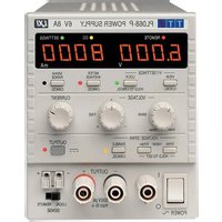


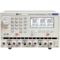
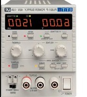
Brand : Aim TTi
Model : TSX 3510P
Category : Programmable power supply