
PL303QMT-P - Power Supply Aim TTi - Free user manual and instructions
Find the device manual for free PL303QMT-P Aim TTi in PDF.


| Product Type | Triple Output Precision Linear DC Power Supply |
| Model | PL303QMT-P |
| Brand | Aim TTi |
| Outputs | Two 0-30V, 0-3A (each) and one 0-6V, 0-8A; parallel mode up to 30V, 6A |
| Operating Modes | Independent, True Parallel, Isolated Tracking, Isolated Ratio Tracking |
| Voltage Setting | Coarse and fine controls; digital V-Span for end-stop limits |
| Current Setting | Single logarithmic control; Low I range (0.1mA resolution on 30V outputs) |
| Meter Display | Dual 4-digit 10mm LED; resolution 10mV/1mA (1mV/0.1mA on low I range for 6V output) |
| Ripple and Noise (20MHz BW) | <0.4mVrms, 2mVp-p (30V outputs); <0.6mVrms, 2mVp-p (6V output) |
| Load Regulation | Voltage: <0.01% + 2mV; Current: typ. <0.01% + 500μA |
| Line Regulation | Voltage: <0.01% + 2mV; Current: <0.01% + 250μA for 10% line change |
| Protections | OVP and OCP (fixed at 105% in local mode), OTP, output reverse diode clamp |
| Digital Interfaces | RS232, USB, LAN (LXI), GPIB (optional) |
| Remote Control (Analogue) | 0-5V or 0-10V inputs for voltage and current; remote off via rear panel |
| AC Input | 230V or 115V ±10%, 50/60Hz, Installation Category II |
| Power Consumption | 840VA max (triple) |
| Dimensions (W x H x D) | 321mm x 131mm (3/4 rack 3U) x 288mm (excluding feet, knobs, terminals) |
| Weight | 12.6 kg |
| Safety Compliance | EN61010-1, EN61326-1 |
| Cooling | Intelligent variable-speed fan with over-temperature shutdown |
| Operating Environment | +5°C to +40°C, 20% to 80% RH, indoor use up to 2000m, Pollution Degree 2 |
| Storage Temperature | -40°C to +70°C |
| Cleaning | Wipe with a damp cloth; do not use solvents or abrasives |
| Reparability | No user-serviceable parts inside; refer servicing to qualified personnel |
Frequently Asked Questions - PL303QMT-P Aim TTi
User questions about PL303QMT-P Aim TTi
0 question about this device. Answer the ones you know or ask your own.
Ask a new question about this device
Download the instructions for your Power Supply in PDF format for free! Find your manual PL303QMT-P - Aim TTi and take your electronic device back in hand. On this page are published all the documents necessary for the use of your device. PL303QMT-P by Aim TTi.
USER MANUAL PL303QMT-P Aim TTi
AIM & THURLBY THANDAR INSTRUMENTS
New PL & PL-P Series
Precision Linear DC Power Supplies
General specifications apply for the temperature range 5° C to 40° C. Accuracy specifications apply for the temperature range 18° C to 28° C after 1 hour warm-up with no load and calibration at 23° C. Typical specifications are determined by design and are not guaranteed.
OUTPUTS
| Voltage/Current Ranges: | |||||
| PL 068 | 0V to 6V/1mA to 8000mA; 0V to 6V/0.1mA to 800mA | ||||
| PL 155 | 0V to 15V/1mA to 5000mA; 0V to 15V/0.1mA to 500mA | ||||
| PL 303 | 0V to 30V/1mA to 3000mA; 0V to 30V/0.1mA to 500mA | ||||
| PL 601 | 0V to 60V/1mA to 1500mA; 0V to 60V/0.1mA to 500mA | ||||
| PL303QMD & PL303QMT | 0V to 30V/1mA to 3000mA; 0V to 30V/0.1mA to 500mA (each 30V output); 0V to 30V/2mA to 6000mA; 0V to 30V/0.2mA to 1000mA (parallel mode). & 0V to 6V/1mA to 8000mA; 0V to 6V/0.1mA to 800mA (PL303QMT O/P3) | ||||
| Note: In manual operation, actual maxima for voltage and current are typically 1% greater than the figures given above. | |||||
| Voltage Setting: | By coarse and fine controls. | ||||
| Current Setting: | By single logarithmic control. | ||||
| Configuration Selection: (PL303QMD & QMT only) | Independent, True parallel, Isolated Tracking & Isolated Ratio Tracking modes via front panel rotary switch. | ||||
| Voltage Span Control (V-Span) | The voltage adjustment range can be controlled by digital setting of the end-stop values of the coarse voltage control to any desired values. The range for Vmax is 0.1V to 6V/15V/30V/60V depending on model. The range for Vmin is 0 to (Vmax - 0.1V). | ||||
| Settings Lock (S-Lock) | Voltage and current settings can be locked by a single button press. Lock accuracy is equal to meter accuracy (see Meter Specification) | ||||
| Output Mode: | Constant voltage or constant current with automatic cross-over. CC indicator lit in constant current mode. | ||||
| Output Switch: | Electronic, non-isolating. Preset voltage and current limit displayed when Output is off. Output rise time with no load <15ms. | ||||
| Output Terminals: | Universal 4mm safety binding posts on 19mm (0·75") spacing for Output; screwless terminals for Sense. | ||||
| Transient Response: | <50μs to within 50mV of set level for a 5% to 95% load change. | ||||
| Voltage Programming Speed (PL-P models): | Maximum time required for output to settle within 1% of its total excursion (for resistive load). Excludes command processing time. | ||||
| Full Load | No Load | Full Load | |||
| 6V 8A | Up | 20ms | 5ms | Down | 5ms |
| 6V 800mA | Up | 20ms | 5ms | Down | 20ms |
| 15V 5A | Up | 45ms | 40ms | Down | 6ms |
| 15V 500mA | Up | 45ms | 40ms | Down | 60ms |
| 30V 3A | Up | 45ms | 40ms | Down | 20ms |
| 30V 500mA | Up | 45ms | 40ms | Down | 50ms |
| 60V 1·5A | Up | 45ms | 40ms | Down | 50ms |
| 60V 500mA | Up | 70ms | 40ms | Down | 110ms |
| Ripple and Noise(20MHz bandwidth): | Normal mode voltage: <0·4mVrms and 2mVp-p (15V, 30V & 60V O/Ps)<0·6mVrms and 2mVp-p (6V O/P) |
| Normal mode current: <0·2mArms; <40μArms Low I range (15/30/60V O/Ps)<0·6mArms; <100μArms Low I range (6V O/P) | |
| Common mode current: <5μArms | |
| Load Regulation: | For any load change, measured at the terminals, using remote sense:Voltage: <(0·01% + 2mV). Add typically 2·5mV for a 0·5V drop in the positive output lead. Specification applies for sense lead resistance <0·5Ω.Current: typically <(0·01% + 500μA). |
| Line Regulation: | Voltage: <(0·01% + 2mV) for 10% line change.Current: <(0·01% + 250μA) for 10% line change. |
| Temperature Coefficient: | Voltage: typically <(50ppm + 0·5mV)/°CCurrent: typically <(100ppm + 1mA)/°C; <(100ppm + 0·1mA)/°C Low I range. |
| Output Protection: | Output will withstand forward voltages of up to 20V (10V on 6V O/P) above rated output voltage. Reverse protection by diode clamp for currents up to 3A. |
| OTP Protection: | Output trips off for over-temperature. |
| OVP and OCPProtection:(PL-P models only) | Measure-and-compare over-voltage and over-current protection are implemented in firmware and can be set via the remote interfaces only.Output trips off for OVP and OCP. Setting resolution: 10mV and 1mA.Response time: typically 500ms.For manual operation (Local mode) OVP and OCP are fixed at 105% of the instrument range maximum. |
METER SPECIFICATIONS
| Display Type: | Dual 4-digit meters, 10mm (0·39") LED. |
| Voltage: | Resolution 10mV, 15/30/60V O/Ps; 1mV, 6V O/P.Accuracy ±(0·1% +10mV) 6/15/30/60V O/Ps. |
| Current: | Resolution 1mA; 0·1mA Low I range.Accuracy ± (0·3% + 3mA) to 3A, ± (0·5% + 3mA) to 6A;± (0·3% + 3mA) to 8A, ± (0·3% + 0·3mA) on Low I range, 6VO/P. |
| Current Meter Average: | Selects a 2s time constant (normally 20ms) for averaging of rapidly varying load currents. |
ADDITIONAL SPECIFICATIONS - PL303QMD/PL303QMT QUAD-MODE DUAL Section
| Independent Mode: | Each output is fully independent and isolated. Operation is equivalent to two single power supplies. |
| Tracking Mode: | The two outputs remain isolated but the Slave voltage controls are disabled and the Slave voltage is set equal to the Master voltage. |
| Tracking Accuracy: | Slave voltage = Master voltage ±(0.1% of Master voltage ±10mV). |
| Ratio (%) Tracking Mode: | As tracking but the Slave voltage controls set an output voltage between 0% and 101% of the Master voltage. Once set, varying the Master voltage will create the same percentage change in the Slave voltage setting. |
| Tracking Accuracy: | % change in Slave voltage = % change of Master voltage ± 0.1% ±10mV. |
| Parallel Mode: | The Master output operates as a single output power supply with twice the current capability (0.2mA to 6A). The Slave is disabled (and its displays are turned off). |
| Both On / Both Off: | Each output has an independent DC On/Off control; these additional keys can be used to turn both outputs on or off simultaneously. These keys operate in all four modes. |
ANALOGUE REMOTE CONTROL (Single PL-P models only)
| Non-isolated inputs and outputs to set voltage and current limit | |
| Control input and output scaling: | Rear panel control inputs (CV and CC) permit external 0V to 5V or 0 to10V signals to set 0 to 100% of rated output voltage and current.Set values of 0 to 100% of rated output voltage and current generate 0 to 5V signals at the rear panel Vout and Iout outputs.These signals are referenced to the positive output. |
| Control input accuracy: | Voltage: 0.3% ±10mV. Input impedance 100kΩ; protected to 60V.Current: 0.5% ±5mA. Input impedance 64kΩ; protected to 60V. |
| Control output accuracy: | Voltage: 0.3% ±10mVCurrent: 0.5% ±5mA.Output impedance: 125Ω; output short-circuit protected. |
| Remote Off: | Rear panel socket allows a switch closure or logic low to turn output off. |
DIGITAL INTERFACES (PL-P models only)
| Full digital remote control facilities are available through the RS232, USB, LAN and GPIB interfaces. | |
| Voltage Setting: | Resolution: 1mV; Accuracy: ± (0·05% + 5mV). |
| Voltage Readback: | Resolution: 1mV; Accuracy: ± (0·1% + 5mV). |
| Current Setting and Current Readback: | Resolution: 0.1mA; 0.01mA on Low I range, except 6V O/P: 1mA & 0.1mA. Accuracy: ± (0·3% + 3mA) to 3A, ± (0·5% + 3mA) to 6A, ± (0·3% + 0·3mA) Low I range, except 6V O/P: ± (0·3% + 3mA) to 8A and ± (0·3% + 0·3mA) on Low I range. |
| RS232: | Standard 9-pin D-connector. Baud rate 9600. |
| GPIB (optional): | Conforming with IEEE488.1 and IEEE488.2 |
| USB: | Standard USB 2.0 hardware connection. Operates as a virtual COM port. |
| LAN: | Ethernet 100/10base-T hardware connection. 1.4 LXI Core 2011. |
| Remote Command Processing Time: | Typically <25ms between receiving the command terminator for a step voltage change at the instrument and the output voltage beginning to change. |
GENERAL
| AC Input: | 230V AC or 115V AC ± 10%, 50/60Hz. Installation Category II |
| Power Consumption: | Single: 280VA max. Dual: 560VA max. Triple: 840VA max. |
| Operating Range: | +5°C to +40°C, 20% to 80% RH |
| Storage Range: | -40°C to +70°C |
| Environmental: | Indoor use at altitudes up to 2000m, Pollution Degree 2. |
| Cooling: | Intelligent variable-speed low noise fan assists convection. Over-temperature trip shuts down output if internal temperatures exceed predetermined thresholds. |
| Safety: | Complies with EN61010-1 |
| EMC: | Complies with EN61326-1 |
| Size:(excluding feet, knobs and terminals) | Single: 107mm x 131mm (1⁄4 rack 3U) x 288mm L (PL-P: 343mm L), Dual: 214mm x 131mm (1⁄2 rack 3U) x 288mm L Triple: 321mm x 131mm (3⁄4 rack 3U) x 288mm L |
| Weight: | Single: 4·5kg (PL-P: 4.9kg); Dual: 8.5kg; Triple: 12.6kg |
ANALOGUE REMOTE CONTROL (Single PL-P models only)
| Non-isolated inputs and outputs to set voltage and current limit | |
| Control input and output scaling: | Rear panel control inputs (CV and CC) permit external 0V to 5V or 0 to10V signals to set 0 to 100% of rated output voltage and current. Set values of 0 to 100% of rated output voltage and current generate 0 to 5V signals at the rear panel Vout and Iout outputs. These signals are referenced to the positive output. |
| Control input accuracy: | Voltage: 0.3% ±10mV. Input impedance 100kΩ; protected to 60V. Current: 0.5% ±5mA. Input impedance 64kΩ; protected to 60V. |
| Control output accuracy: | Voltage: 0.3% ±10mVCurrent: 0.5% ±5mA.Output impedance: 125Ω; output short-circuit protected. |
| Remote Off: | Rear panel socket allows a switch closure or logic low to turn output off. |
DIGITAL INTERFACES (PL-P models only)
| Full digital remote control facilities are available through the RS232, USB, LAN and GPIB interfaces. | |
| Voltage Setting: | Resolution 1mV, Accuracy ± (0·05% + 5mV) |
| Voltage Readback: | Resolution 1mV, Accuracy ± (0·1% + 5mV) |
| Current Setting and Current Readback: | Resolution: 0.1mA; 0.01mA on Low I range, except 6V O/P: 1mA & 0.1mA.Accuracy: ± (0·3% + 3mA) to 3A, ± (0·5% + 3mA) to 6A, ± (0·3% + 0·3mA) Low I range, except 6V O/P: ± (0·3% + 3mA) to 8A and ± (0·3% + 0·3mA) on Low I range. |
| RS232: | Standard 9-pin D-connector. Baud rate 9600. |
| GPIB (optional): | Conforming with IEEE488.1 and IEEE488.2 |
| USB: | Standard USB 2.0 hardware connection. Operates as a virtual COM port. |
| LAN: | Ethernet 100/10base-T hardware connection. 1.4 LXI Core 2011. |
| Remote Command Processing Time: | Typically <25ms between receiving the command terminator for a step voltage change at the instrument and the output voltage beginning to change. |
GENERAL
| AC Input: | 230V AC or 115V AC ± 10%, 50/60Hz. Installation Category II |
| Power Consumption: | Single: 280VA max. Dual: 560VA max. Triple: 840VA max. |
| Operating Range: | +5°C to +40°C, 20% to 80% RH |
| Storage Range: | -40°C to +70°C |
| Environmental: | Indoor use at altitudes up to 2000m, Pollution Degree 2. |
| Cooling: | Intelligent variable-speed low noise fan assists convection. Over-temperature trip shuts down output if internal temperatures exceed predetermined thresholds. |
| Safety: | Complies with EN61010-1 & EN61326-1.For details, request the EU Declaration of Conformity for this instrument via http://www.aimtti.com/support (serial no. needed). |
| Size:(excluding feet, knobs and terminals) | Single: 107mm x 131mm (1⁄4 rack 3U) x 288mm L (PL-P: 343mm L), excluding feet, knobs and terminals.Dual: 214mm x 131mm (1⁄2 rack 3U) x 288mm LTriple: 321mm x 131mm (3⁄4 rack 3U) x 288mm L |
| Weight: | Single: 4·5kg (PL-P: 4.9kg). Dual: 8.5kg. Triple: 12.6kg |
Sicherheit
EINFACH
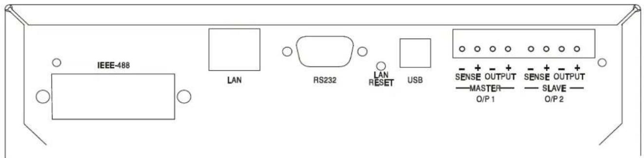
DOPPEL
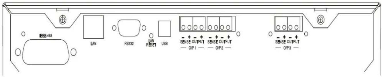
DREIFACH

| Source Handshake | SH1 |
| Acceptor Handshake AH1 | |
| Talker T6 | |
| Listener L4 | |
| Service Request SR1 | |
| Remote Local | RL2 |
| Parallel Poll PP1 | |
| Device Clear DC1 | |
| Device Trigger DT0 | |
| Controller C0 | |
| Electrical Interface | E2 |
| bit 7 = | X Unbeachtet lassen | |
| bit 6 = | 1 | Aktivierung der Parallelabfrage |
| bit 5 = | 1 | |
| bit 4 = | 0 | |
| bit 3 = | Sense | Wert des Antwortbits; 0 = low, 1 = high |
| bit 2 = | ? | Bitposition der Antwort |
| bit 1 = | ? | |
| bit 0 = | ? | |
| Status Byte Register | = 0 |
| Service Request Enable Register † | = 0 |
| Standard Event Status Register | = 128 (nach Setzen des Bits) |
| Standard Event Status Enable Register † | = 0 |
| Execution Error Register | = 0 |
| Query Error Register | = 0 |
| Parallel Poll Enable Register † | = 0 |
Thurlby Thandar Instruments Ltd.
Glebe Road • Huntingdon • Cambridgeshire • PE29 7DR • England (United Kingdom)
Telephone: +44 (0)1480 412451 • Fax: +44 (0)1480 450409
International web site: www.aimtti.com • UK web site: www.aimtti.co.uk • USA web site: www.aimtti.us
Email: info@aimtti.com


Brand : Aim TTi
Model : PL303QMT-P
Category : Power Supply