TBC 32000 XFL BK - Cooker TEKA - Free user manual and instructions
Find the device manual for free TBC 32000 XFL BK TEKA in PDF.

| Brand | Teka |
| Model | TBC 32000 XFL BK |
| Product type | Built-in ceramic hob |
| Number of cooking zones | 2 |
| Configuration of cooking zones | 1 double zone (1400/2000W) + 1 single zone (1200W) |
| Total power | 3000 W |
| Supply voltage | 230 V ~ 50/60 Hz |
| Dimensions (H x W x D) | 90 x 300 x 510 mm |
| Recess dimensions (W x D x Depth) | 280 x 490 x 40 mm |
| Control | Rotary knobs (positions 0-12) |
| Residual heat indicators | Yes, per zone |
| Double zone function | Independent switching of inner/outer circuit |
| Safety | Tempered ceramic glass, automatic shut-off in case of overheating, child lock not present |
| Installation | Recessed into worktop 20-40 mm, minimum distance 650 mm under extractor hood |
| Electrical connection | Omnipolar switch with contact opening ≥ 3 mm, mandatory earthing |
| Glass maintenance | Special ceramic hob products, scraper for burnt residues, no steam cleaner |
| Frame maintenance | Damp cloth, mild detergent, avoid abrasive pads |
| Surface material | Black ceramic glass |
| Color | Black (BK) |
| Warranty | According to manufacturer's conditions, requires invoice and warranty certificate |
Frequently Asked Questions - TBC 32000 XFL BK TEKA
User questions about TBC 32000 XFL BK TEKA
0 question about this device. Answer the ones you know or ask your own.
Ask a new question about this device
Download the instructions for your Cooker in PDF format for free! Find your manual TBC 32000 XFL BK - TEKA and take your electronic device back in hand. On this page are published all the documents necessary for the use of your device. TBC 32000 XFL BK by TEKA.
USER MANUAL TBC 32000 XFL BK TEKA
natural_image
Modern kitchen interior with glossy black walls, ovenetry, and ceiling lighting (no visible text or symbols)User Manual
ES DE
PT FR
TR PL
EN RU
ES INSTRUCCIONES PARA LA INSTALACIÓN Y RECOMENDACIONES DE USO Y MANTENIMIENTO ENCIMERAS VITROCERÁMICAS TOUCH CONTROL....1
PT INSTRUÇÕES DE INSTALAÇÃO E RECOMENDAÇÕES PARA A UTILIZAÇÃO E MANUTENÇÃO PLACAS DE COZINHA VITROCERÂMICAS TOUCH CONTROL....15
TR KULLANMA VE MUHAFAZA İÇİN KURULUM TALİMATLARI VE TAVSİYELERİ SERAMİK ISITMA PLAKALARI DOKUNMATİK KONTROL....20
EN INSTALLATION INSTRUCTIONS AND RECOMMENDATIONS FOR USING AND MAINTAINING CERAMIC HOT PLATES TOUCH CONTROL....33
DE MONTAGEANLEITUNG UND EMPFEHLUNGEN ZUR VERWENDUNG UND WARTUNG GLASKERAMIK-KOCHFELDER MIT TOUCH CONTROL....45
FR INSTRUCTIONS POUR L'INSTALLATION ET CONSEILS D'UTILISATION ET D'ENTRETIEN PLAQUES DE CUISSON VITROCÉRAMQIUE TOUCH CONTROL....58
PL INSTRUKCJA OBSŁUGI, MONTAŻU ORAZ WSKAZÓWKI DOTYCZĄCE PIELEGNACJI CERAMICZNYCH PŁYT KUCHENNYCH TOUCH CONTROL....71
RU ИНСТРУКЦИЯ ПО УСТАНОВКЕ И РЕКОМЕНДАЦИИ ПО УХОДУ И ИСПОЛЬЗОВАНИЮ КЕРАМИЧЕСКИХ ВАРОЧНЫХ ПАНЕЛЕЙ СЕНСОРНОЕ ПРАВЛЕНИЕ....83
Instalación / Instalação / Installation / Montage / Installation / Kurulum / Montaz / Instalace / Inštalácia / Instalare / Installazione / Installatie \_\_\_\_ التركيب
Distancias mínimas / Distâncias mínimas / Minimum distances / Mindestabstände / Distances minimales / Minimum mesafeler / Minimalne odległości / Minimální vzdálenosti / Minimálne vzdialenosti / Distanțe minime/ Distanze minime / Minimumafstanden / alحد الأدنى للمسافات
FAST-CLICK SYSTEM
Horno Teka / Forno TEKA / TEKA Oven / TEKA-Herd / Four TEKA / TEKA / Piekarnik TEKA / TEKA sütő / Trouba TEKA / Rúra na pečenie TEKA / TEKA Cuptor / TEKA Ugn / TEKA Ovn / TEKA-ovn / Teka-uuni / Fomo Teka / TEKA Oven /
natural_image
Diagram of a hand using a tool to press or install a layered electronic component, with an inset showing a device (no text or symbols present)
natural_image
Simple diagram with four circles and a dashed circle, no text or symbols present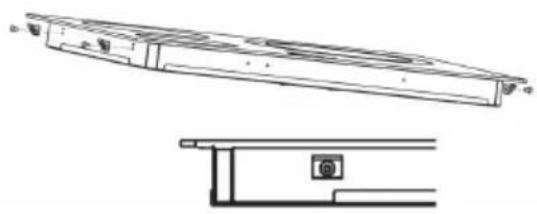
natural_image
Technical line drawing of a mechanical component with top and side views (no text or symbols)ES
TBC 32000 XFL BK
1 Placa de 1.800 Watios.1 Placa de 1.800 Watios.
2 Placa de 1.200 Watios. 2 Placa de 1.200 Watios.
natural_image
Line drawing of a washing machine front panel with a circular dial indicator (no text or symbols)natural_image
Line drawing of a washing machine front panel with a circular dial indicator (no text or symbols)natural_image
Line drawing of a washing machine front panel with a circular dial indicator (no text or symbols)şekil 6
1 1,200 watt hotplate.
2 1,800 watt hotplate.
3 1,800 watt hotplate.
4 1,200 watt hotplate.
5 Residual heat indicator lights.
* Maximum electric power: 6000 watts.
GB TBC 32000 XFL BKTBC BK
1 1800 watt hotplate.
2 1200 watt hotplate.
3 Residual heat indicator lights.
* Maximum electric power: 3000 watts.
DE
FR 1 Plaque de 1.800 Watts.
Guide to Using the Instructions Booklet
Dear customer,
We are delighted that you have put your trust in us.
We are confident that the new hob that you have purchased will fully satisfy your needs.
This modern, functional and practical model has been manufactured using top-quality materials that have undergone strict quality controls throughout the manufacturing process.
Before installing and using it, we would ask that you read this Manual carefully and follow the instructions closely, as this will guarantee better results when using the appliance.
Keep this Instruction Manual in a safe place so that you can refer to it easily and thus abide by the guarantee conditions.
In order to benefit from this Guarantee, it is essential that you submit the purchase receipt together with the Guarantee certificate.
You should keep the Guarantee Certificate or, where relevant, the technical datasheet, together with the Instruction Manual for the duration of the useful life of the appliance. It has important technical information about the appliance.
Safety instructions
Before first use, you should carefully read the installation and connection instructions.
These hob models may be installed in the same kitchen furniture units as TEKA brand ovens.
For your safety, installation should be carried out by an authorised technician and should comply with existing installation standards. Likewise, any internal work on the hob should only be done by TEKA's technical staff, including the change of the flexible supply cable of the appliance.
Safety warnings:
⚠️If the ceramic glass breaks or cracks, immediately unplug the stove-top to avoid electric shocks.
This appliance is not designed to work with an external timer (not built into the appliance) or a separate remote control system.
Do not steam clean this device.
The device and its accessible parts may heat up during operation. Avoid touching the heating elements. Children younger than 8 years old must stay away from the stovetop unless they are permanently supervised.
This device may solely be used by children 8 years old or older, people with impaired physical, sensory or mental abilities, or those who lack experience and knowledge, ONLY when supervised or if they have been given adequate instruction on the use of the device and understand the dangers its use involves. User cleaning and maintenance may not be done by unsupervised children.
Children must not play with the device.
Precaution. It is dangerous to cook with fat or oil without being present, as these may catch fire. Never try to extinguish a fire with water! in this event disconnect the device and cover the flames with a lid, a plate or a blanket.
Do not store any object on the co-oking areas of the stovetop. Prevent a possible fire hazard.
Important
INSTALLATION AND SETUP SHOULD BE CARRIED OUT BY AN AUTHORISED TECHNICIAN IN LINE WITH CURRENT INSTALLATION STANDARDS.
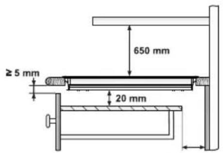
Positioning the hobs
Depending on the model to be installed, an opening with the dimensions shown in figure 2 will be cut into the unit's worktop.
The system for fixing the hob is intended for use with kitchen units with a thickness of 20, 30 and 40 mm. In the packaging of the models VTN DC and TC 620, there is a template included that is for use in sizing the space for these glass ceramic hob models.
See the fitting hole's dimensions for each model on the "dimensions and characteristics" table of this manual. The minimum distance between the surface supporting the cooking pans and the lower part of the kitchen unit or the hood located above the hob should be 650 mm. If the hood's installation instructions recommend that the gap is greater than this, you should follow this advice.
The hobs described in this manual can only be installed with Teka ovens. Models with no control knobs are only to be installed with Teka ovens and/or Teka control panels.
The unit where the hob and oven will be located will be suitably fixed.
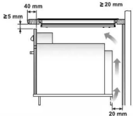
INSTALLATION WITH A CUTLERY DRA- WER OR LOW CUPBOARD (TOUCH CONTROL MODELS)
If you wish to have a cupboard or cutlery drawer beneath the hob, you should install

a panel to separate them. This will prevent accidental contact with the hot surface of the body of the appliance.
The board should be installed 20 mm below the bottom of the hob and an empty
Fitting holes
fig. 2
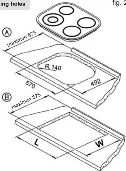
(A) Mod.: VTN DC and TC 620
⑧ Mod.: Rest of the models The dimensions L and W are shown in the table "Dimensions and characteristics" of the Technical Information section.
space of at least 20 mm should be left at the back of the cupboard. As an alternative to this type of panel, you can install a detachable protective cover to the bottom of the hob, which can be obtained from our Technical Services using the reference indicated.
Protective cover
| Ref. Models | |
| 81253177 | TT 600, TB 600, TR 640, TT 640, TR 620, TT 630, TR 600, TR 735 AB, TM 620, TR 641, TM 601 and TB 641 |
| 81253176 | TT 620 and TC 620 |
When hobs are handled before being installed, care should be taken in case there is any protruding part or sharp edge which could cause injury.
When installing units or appliances above the hob, the hob should be
protected by a board so that the glass cannot be damaged by accidental blows or heavy weights.
The glues used in manufacturing the kitchen unit and in the adhesive on the decorative laminate of the worktop surface should be made to tolerate temperatures of up to 100°C.
TEKA assumes no responsibility for any malfunction or damage caused by faulty installation.
PLEASE REMEMBER THAT THE GUARANTEE DOES NOT COVER THE GLASS IF IT SUFFERS A VIOLENT BLOW OR IF IT IS USED IMPROPERLY.
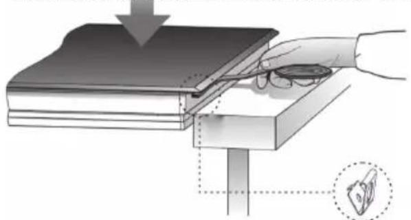
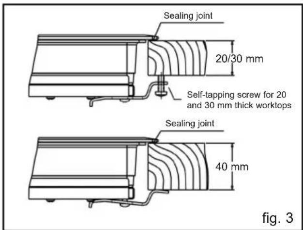
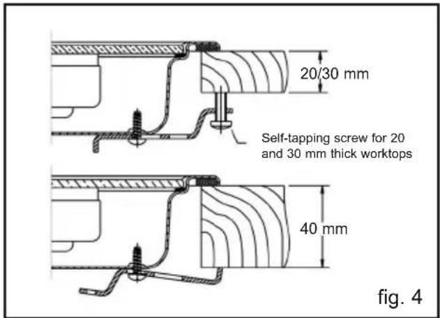
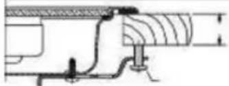
Fixing the hob (see figs. 3 and 4)
When the gap has been properly sized, the sealing washer should be put on the lower part of the hob. With models VR 622, TR 620, TR 640, TT 640, TT 600, TB 600, TR 600, TT 630, TR 735 AB, TM 620, TR 641, TM 601 and TB 641 the washer will be stuck to the lower face of the glass.
Silicone should not be applied between the glass and the unit worktop because if it becomes necessary to remove the hob from its position, the glass could break when trying to detach it.
Position the clips as shown in the diagram, fastening them to the openings in the lower part of the body using the screws provided.
For worktop thicknesses of 30 mm. or less, use the self-tapping screws that are provided as a fastening accessory - put them into the clip's round hole. This hole will be threaded as the screw is inserted into it, and this should be done before fixing the clip to the worktop.
The clips and the sealing joint are provided, and can be found in the packaging.
Connecting the electricity
Before connecting the hob to the electric mains, check that the voltage and frequency of the mains matches what is shown on the hob's rating plate, which is located lower down, and on the guarantee certificate or, where appropriate, the technical datasheet supplied, which should be kept together with this manual.
The electric connection is made via an om-nipolar switch or plug where accessible, which is suitable for the intensity to be tolerated and which has a minimum gap of 3 mm between its contacts, which will ensure disconnection in case of emergency or when cleaning the hob.
The connection should include correct earthing, in compliance with current norms.
If the flexible supply cable fitted to the VT CM hob model ever needs to be changed, it should be replaced by TEKA's official service.
The input cable should not be in contact either with the body of the hob or with the body of the oven, if the oven is installed in the same unit.
Positioning the oven

See the corresponding manual.
The oven's placement should be as shown in your instruction manual, and the manual should also be referred to when connecting the electricity. Before accessing the inside of the appliance, the appliance should be disconnected from the power.
Joining the hob to the oven or the control panel
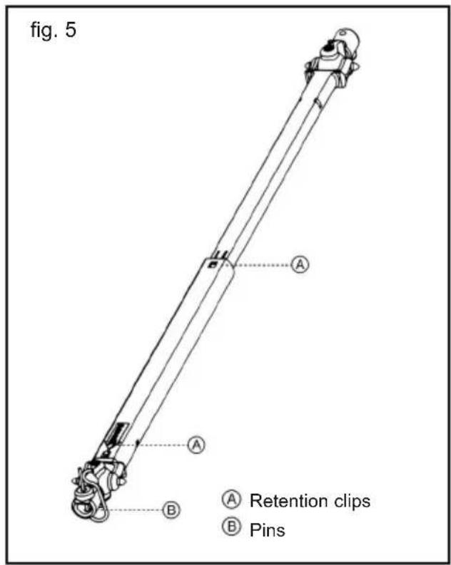
For this purpose, four cardan telescopic shafts are included with the hob. (See fig. 5). The way to join them is as follows:
1 Turn off the electricity.
2 Detach the cardan telescopic shafts by pressing on the retention clip (A), where it says PUSH, with a slim screwdriver, and pull the extension out a few centimetres.
3 Remove the four pins from the ends (B).
4 Put the oven part-way into its space, taking care not to drag the cardan telescopic shafts coming from the hob, and leaving enough space to put in the other ends of the telescopic shafts into the shafts in the rear part of the control panel, and then replace the pins. (See fig. 5)
5 To make the electric connection between the two appliances, attach the hob's connector to oven's connector.
6 Complete the definitive positioning of the oven, ensuring that the cardan telescopic shafts are firmly in position and that the telescopic pipes are well-aligned when inserted so that sliding is quite simple.
7 Position the controls on the front of the oven.
8 To operate the control knobs, they first have to be pressed in, and then turned in order to release the safety device.
Rear view of the Control Panel:
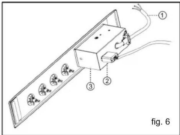
① Flexible supply cable
② Connector
③ Protective box for electrical assembly
If the cardan telescopic shafts are too short, extensions can be added (not provided, but available as an accessory). These are added by pressing, and they are fixed by the cover that is included.
Dimensions and Characteristics
| Models | TBC 64000 XFL BK | TBC 32000 XFL BK |
| Hob dimensions | ||
| Height (mm) | 85 90 | |
| Length (mm) | 600 300 | |
| Width (mm) | 510 510 | |
| Dimensions of the placement in the unit | ||
| Length (mm) (L) | 580 280 | |
| Width (mm) (W) | 492 490 | |
| Depth (mm) | 60 40 | |
| Configuration | ||
| Double radiant hotplate700/2100W circuit | ||
| Double radiant hotplate1400/2000W circuit | ||
| 2100W radiant hotplate | ||
| 1800W radiant hotplate | 2 | 1 |
| 1500W radiant hotplate | ||
| 1200W radiant hotplate | 2 | 1 |
| Electrics | ||
| Nominal Power(W) for 230 V | 6000 | 3000 |
| Supplyvoltage (V) | 230 | 230 |
| Frequency (Hz) | 50/60 50/60 | |
Ceramic hobs with controls instructions
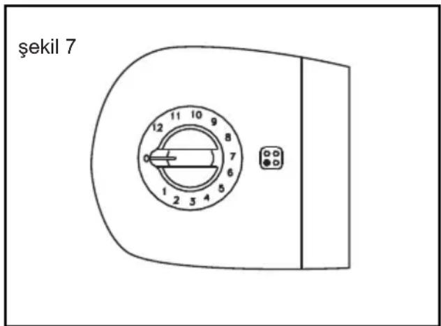
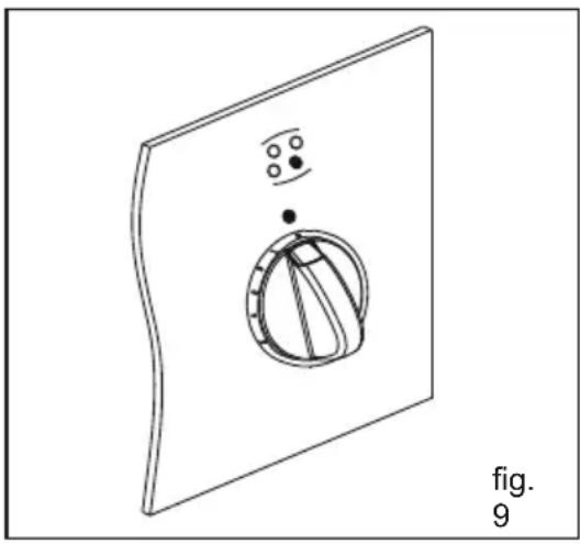
Each of the glass ceramic hob's heating elements is connected to a power regulator that controls the operating and stoppage time of each of them (more or less heat). (See fig. 9)
Each power regulator control knob has numbering from "0" to "12".
natural_image
Diagram of a mechanical component with a circular housing and mounting holes, labeled 'fig. 9' (no text or symbols on the diagram itself)The hob with the integrated controls (model VT CM) has the numbering on the glass. (See fig. 10).
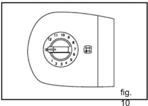
At position “0” the hob does not operate, at position “1” there is not much operating time but a great deal of stoppage time. With the remaining control knob positions, the operating time increases while the stoppage time decreases, until at position “12” where operation is continuous, only cutting off when the warm hotplate’s thermostat cuts in to turn off the power when the maximum permitted temperature is reached.
DOUBLE CIRCUIT INSTRUCTIONS
The double circuit heating elements are hotplates made up of two mutually independent heating elements, and they are controlled by a power regulator that allows the smaller, inside ring to be turned on, or both inside and outside at the same time. To only have the inside ring turned on, turn the control knob clockwise and set it to the position you require. To turn on the whole hotplate, set the control to position “12” and go on turning, gently, until it goes past “0” and you hear a “CLICK”. Then set the control to the position required. When the whole hotplate is turned on, and you only want to have the smaller ring working, set the control to ZERO and then turn it on again.
Whether only one ring is turned on, or both, you can regulate the temperature by setting the control to intermediary positions, just as with the normal and halogen hobs described in the previous paragraph.
With double circuit regulators, when the control is set to "0" it may only be turned clockwise, as there is a catch which prevents you moving from "0" to "12" and vice-versa.
Before turning on one of the hob's heating elements, you should identify the corresponding control. To this end, it is shown beside each control which heating element it corresponds to.
The amber indicator light at the front of the controls shows that one or more heaters is in operation. The indicator light is situated below the glass on the model VT CM.
RESIDUAL HEAT INDICATORS
When a heating area reaches a temperature of more than 60 ± 15^ the corresponding residual heat indicator comes on, and stays on - even if the control is set to zero - until the temperature drops. However,
special attention should be paid to the temperature of the cooking area because there is a possibility, albeit remote, that the indicator will fail and that the temperature in that area will not be shown.
Advice on using the hotplates effectively
In order to achieve the best results from cooking, the following guidelines should be followed:
* Use pans with a flat base, as the greater the surface contact between the pan and the glass, the greater will be the heat transmission. Figure 11 shows how pans that are dented or concave have a smaller contact surface.
fig. 11
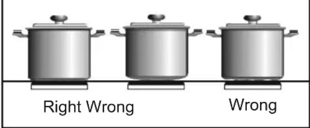
* We recommend the use of heavy pans so that the base is more difficult to dent.
* The use of pans with a diameter which is smaller than that indicated in the heating area is not recommended.
* Make sure that the pans are well centred on the outlines shown on the heating area.
* Dry the pans' bases before putting them on the glass ceramic hob.
* Do not leave any plastic object or utensil, or any aluminium foil, lying on the glass hob.
* Do not drag pans with corners or edges that could damage the glass.
* Do not use the glass ceramic hob without a pan on the area that is switched on.
* Do not cook with plastic pans.
* Pans should be made of a material which is heat-resistant so that they do not melt on the glass.
* The glass will tolerate bangs from big pans that do not have sharp edges. Be careful with impacts from small, sharp instruments.
Avoid spilling sugar, or products containing sugar, on the glass, since these may react with the glass and damage the surface.
Cleaning and care
To maintain the glass ceramic hob in good condition, it should be cleaned with suitable products. The glass ceramic hob should be cleaned each time it is used, when it is either lukewarm or cool. This makes cleaning easier and avoids dirt accumulating through repeated use.
Never use aggressive cleaning products or products that can scratch the surfaces (the table below shows various common products that may be used). Neither should steam-based appliances be used to clean the hob.
CLEANING AND CARE THE GLASS
The degree of soiling should be taken into account when cleaning, and the items and products used should vary according to this.
Light soiling
Light, non-sticky, soiling can be cleaned with a damp cloth and a soft detergent or warm, soapy water.
Heavy soiling
Serious dirt and grease should be cleaned using an agent specially made for glass ceramic. Please follow the manufacturer's instructions.
Sticky stains that have been burned in can be removed by using a scaper with a razor blade.
Rainbow colouring: Caused by pans that have dry bits of grease on their base or when grease gets between the glass and the pan while cooking. Can be removed from the surface of the glass using a nickel scourer with water or with a special glass ceramic cleaner.
Plastic objects, sugar, or food with a high sugar content that are melted onto the hob should be removed immediately while hot, using a scraper.
When the glass' colour changes.
This does not affect its effectiveness or stability, and is generally caused by inadequate cleaning or by poor-quality pans.
Metallic sheens are caused by metal pans sliding over the glass. They can be removed by thorough cleaning with a special, glass ceramic cleaning agent, although it may be that the cleaning needs to be repeated more than once.
Worn trim is the result of using abrasive cleaning products or pans with uneven bases which wear down the serigraphy.
Take great care when using the glass scraper. The blade can cause injury!
⚠️ Only use the blade on the glass ceramic surface - avoid the body of the scraper coming into contact with the glass, since this could scratch the glass ceramic.
⚠️ Use blades that are in perfect conditions, and change the blade as soon as it shows any sign of wear.
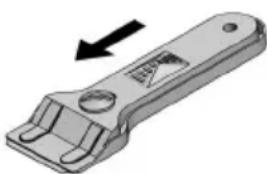
Using the scraper
fig. 12
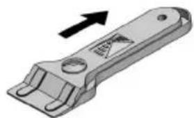
natural_image
3D illustration of a mechanical wrench with an arrow indicating direction (no text or symbols)Protected blade
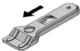
natural_image
3D illustration of a mechanical tool with an arrow indicating direction (no text or symbols)Unprotected blade

RECOMMENDED CLEANING PRODUCTS
| Product | Should it be used to clean... | |
| ... the glass? | ... the surround? | |
| Soft and liquid detergents | YES YES | |
| Aggressive or powder detergents | NO NO | |
| Special glass ceramic cleaning agents | YES YES | |
| Grease-removing sprays (ovens, etc.) | NO NO | |
| Soft cloths | YES YES | |
| Kitchen towels | YES YES | |
| Kitchen cloths | YES YES | |
| Nickel scourers (never use dry) | YES NO | |
| Steel scourers | NO NO | |
| Hard synthetic scourers (green) | NO NO | |
| Soft synthetic scourers (blue) | YES YES | |
| Glass scrapers | YES NO | |
| Liquid polish for domestic appliances and/or glass | YES YES | |
When you finish using the scraper, fold it away and cover it well up. (See fig. 12).
⚠️ Pans may stick to the glass if something has melted between them. Do not attempt to unstick the pan when it is cold - you could break the glass ceramic.
Do not stand on the glass or lean on it, for it might break and cause injury. Do not put any objects down on the glass.
CLEANING AND CARE THE FRAME
Clean dirt off using a damp cloth or warm, soapy water. With stubborn stains, use a special glass ceramic cleaning agent, or a liquid polish for domestic appliances. Rub the product on without diluting it, leave it to work, and then wipe off with a dry cloth. Do not use metal scourers or hard synthetics.
TEKA INDUSTRIAL S.A. reserves the right to alter its manuals in any way it deems necessary or useful while not altering their basic characteristics.
Environmental considerations
The symbol 📋 on the product or on its packaging indicates that this product may not be treated as household waste. Instead it shall be handed over to the applicable collection point for the recycling of electrical and electronic equipment. By ensuring this product is disposed of correctly, you will help prevent potential negative consequences for the environment and human health, which could otherwise be caused by inappropriate waste handling of this product, please contact your local city offi-
ce, your household waste disposal service or the shop where you purchased the product.
Packaging materials are organic and fully recyclable. Plastic components are identified by marking >PE<, >LD<, >EPS<, etc. Throw out packaging materials, such as household waste, in the container of your municipality.
If something doesn't work
Before calling the Technical Service, please make the following checks:
| Fault Possible cause Possible solution | ||
| FOR ALL THE MODELS: | ||
| Neither the hotplates nor the pilot lights are working | ||
| The cable is not connected to the mains | Connect the cable to the mains | |
| The pan is sticking to the glass | ||
| Something has melted between the pan and the glass. | Set the hotplate to full power and try to unstick it. | |
| Check the bases of your pans and do not slide them across the glass. | ||
| Pans with aggressive bases. | ||
natural_image
Line drawing of a device with a circular component and three dots, labeled 'Abb. 9' (no text or symbols on the diagram itself)natural_image
Two identical mechanical clamp components shown in 2D views, each with an arrow indicating direction (no text or symbols present)natural_image
Diagram of a device with a spherical component and three dots, labeled 'fig.' and '9' (no text or symbols on the diagram itself)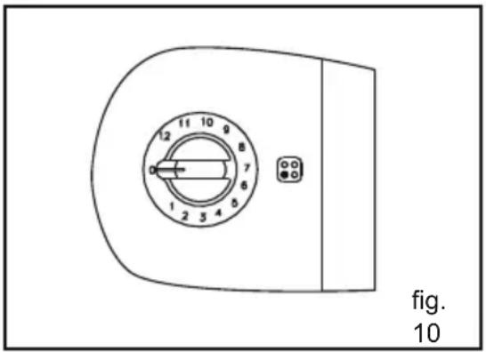
natural_image
3D illustration of a mechanical clamp or lever component with an arrow indicating direction (no text or symbols)Lame bloquée
natural_image
3D illustration of a mechanical wrench with an arrow indicating direction (no text or symbols)Lame sortie
natural_image
Diagram of a washing machine with a circular component and mounting holes (no text or symbols)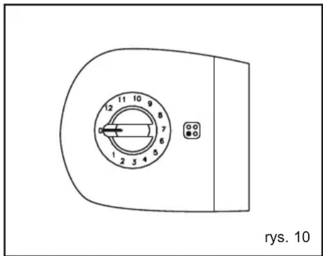
natural_image
3D rendering of a mechanical clamp or bracket component with an arrow indicating direction (no text or symbols)natural_image
3D rendering of a mechanical wrench handle with an arrow indicating direction (no text or symbols)natural_image
Technical line drawing of a mechanical component with internal channels and mounting base (no text or symbols)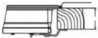
natural_image
Pure technical line drawing of a mechanical component without any text, numbers, or symbolsРис.4
natural_image
Pure technical diagram of a mechanical assembly without any text, numbers, or symbols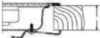
natural_image
Pure technical diagram showing a pipe connection with hatched areas and a small inset detail (no text or symbols)На рисунке:
natural_image
Simple line drawing of a basketball hoop with a flag, no text or symbols present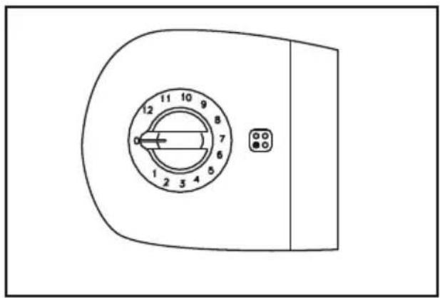
natural_image
Technical line drawing of a door with numbered dial (no text or symbols)natural_image
Two identical mechanical component diagrams with arrows indicating direction (no text or symbols)Country Subsidiary Address City Phone
| AustriaKüppersbusch Austria | Eitnergasse, 13 | 1231 Wien | +43 18 668 022 |
| BelgiumKüppersbusch Belgium S.P.R.L. | Doomveld Industrie, Asse 3, No. 11 - Boite 7 | 1731 Zellik | +32 24 668 740 |
| BulgariaTeka Bulgaria EOOD | Blvd. “Tsarigradsko Shosse” 135 | 1784 Sofia | +359 29 768 330 |
| ChileTeka Chile S.A. | Avd El Retiro Parque los Maitenes, 1237. Parque Enea | Pudahuel, Santiago de Chile | + 56 24 386 000 |
| ChinaTeka International Trading (Shanghai) Co. Ltd. | No.1506, Shengyuan Henghua Bldg. No.200 Wending Rd. | Xuhui, Dist. 200030 Shanghai | +86 2 153 076 996 |
| Czech RepublicTeka CZ S.R.O. | V Holesovickách, 593 | 182 00 Praha 8 - Liben | +420 284 691 940 |
| EcuadorTeka Ecuador S.A. | Parque Ind. California 2, Via a Daule Km 12 | Guayaquil | +593 42 100 311 |
| GreeceTeka Hellas A.E. | Thesi Roupaki - Aspropyrgos | 193 00 Athens | +30 2 109 760 283 |
| HungaryTeka Magyarország Zrt. | Terv u. 92 | 9200 Mosonmagyaróvár | +36 96 574 500 |
| IndonesiaPT Teka Buana | Jalan Menteng Raya, Kantor Taman A9 Unit A3 | 12950 Jakarta | +62 215 762 272 |
| MalaysiaTeka Küchentechnik (Malaysia) Sdn Bhd | 10 Jalan Kartunis U1/47, Temasya Park, Off Glenmarie | 40150 Shah Alam, Selangor Darul Ehsan | +60 376 201 600 |
| MexicoTeka Mexicana S.A. de C.V. | Blvd Manuel A. Camacho 126, Piso 3 Col. Chapultepec | 11000 Mexico D.F. | +52 5 551 330 493 |
| MoroccoTeka Maroc S.A. | 73, Bd. Slimane, Depôt 33, Route de Ain Sebaa | Casablanca | +212 22 674 462 |
| PeruTeka Küchentechnik Perú S.A. | Av. El Polo 670 local A 201, CC El polo, Surco | Lima | +51 14 363 078 |
| PolandTeka Polska Sp. ZO.O. | ul. 3-go Maja 8 / A2 | 05-800 Pruszkow | +48 227 383 270 |
| PortugalTeka Portugal S.A. | Estrada da Mota - Apdo 533 | 3834-909 Ilhavo, Aveiro | +35 1 234 329 500 |
| RomaniaS.C. Teka Küchentechnik Romania S.R.L. | Sevastopol str., no 24, 5th floor, of. 15 | 010992 Bucharest Sector 1 | +40 212 334 450 |
| Russia/PоссияTeka Rus LLC/OOO "Teka Рус" | Neverovskogo 9, Office 417, 121170, Moscow, Russia | 121087 Россия, Москва | +7 4 956 450 064 |
| SingaporeTeka Singapore PTE Ltd | Clemenceau Avenue, 83, 01-33/34 UE Square | 239920 Singapore | +65 67 342 415 |
| SpainTeka Industrial, S.A. | C/ Cajo,17 | 39011 Santander | +34 942 355 050 |
| ThailandTeka (Thailand) Co. Ltd. | 364/8 Sri-Ayuttaya Road, Phayathai, Ratchatavee | 10400 Bangkok | +66 -26 424 888 |
| TurkeyTeka Teknik Mutfak Aletleri Sanayi Ve Tic A.S. | Levent Mah. Comert Sk. Yapı Kredi Bloklari Sit. C Blok Apt. No.1 C/32 | 34330 Besiktas, Istanbul | +90 2 122 883 134 |
| UkraineTeka Ukraine LLC | 86-e, Bozhenko Str .2nd floor,4th entrance | 03150 Kyiv | +380 444 960 680 |
| United Arab EmiratesTeka Middle East Fze | Building LOB 16, Office 417 | P.O. Box 18251 Dubai | +971 48 872 912 |
| United Arab EmiratesTeka Küchentechnik U.A.E LLC | Bin Khedia Centre | P.O. Box 35142 Dubai | +971 42 833 047 |
| VenezuelaTeka Andina S.A. | Ctra. Petare-Santa Lucia, km 3 (El Limoncito) | 1070 Caracas | +58 2 122 912 821 |
| VietnamTEKA Vietnam Co., Ltd. | 803, Fl 8th, Daiminh Convention Center, 77, Hoang Van | Thai, Tan Phu Ward, District 7, Ho Chi Minh | +84 854 160 646 |
TEKA