
MFLF1 - TV Stand SANUS - Free user manual and instructions
Find the device manual for free MFLF1 SANUS in PDF.

User questions about MFLF1 SANUS
0 question about this device. Answer the ones you know or ask your own.
Ask a new question about this device
Download the instructions for your TV Stand in PDF format for free! Find your manual MFLF1 - SANUS and take your electronic device back in hand. On this page are published all the documents necessary for the use of your device. MFLF1 by SANUS.
USER MANUAL MFLF1 SANUS
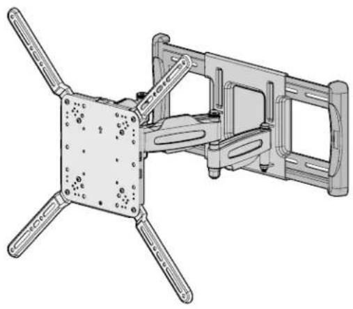
Universal Large Full-Motion TV Wall Mount
Compatible with Amazon Fire TVs
INSTRUCTION MANUAL
| Want to watch a video that shows how easy this DIY project will be?SANUS.com/3010 SANUS.com/2567 | Get it right the first time. Height-Finder™ shows you where to drill. | Our install experts are standing by to help.US: +1 (800) 359-5520EMEA: +31 (0) 495 580 852UK: +44 (0) 800 056 2853 |
IMPORTANT SAFETY INSTRUCTIONS - PLEASE READ ENTIRE MANUAL PRIOR TO USE - SAVE THESE INSTRUCTIONS
Before getting started, let's make sure this mount is perfect for you!
| 1 Does your TV (including accessories) weigh more than 110 lb (49.8 kg)? | No - Perfect! Yes - This mount is NOT compatible. Visit MountFinder.sanus.com or call US: +1 (800) 359-5520 | EMEA: +31 (0) 495 580 852 | UK: +44 (0) 800 056 2853 to find a compatible mount. | ||||
| 2 What is your wall made of? | CAUTION: DO NOT install into drywall alone | Drywall with wood studs? Perfect! | Concrete kit CMKI (not included) Call Customer Service: US: +1 (800) 359-5520 | EMEA: +31 (0) 495 580 852 | UK: +44 (0) 800 056 2853 | ||
| 3 Do you have all the tools needed? | Tape Measure | Pencil Level | Screwdriver | Electric Drill | 1/2 in. (13 mm) Socket Wrench |
| 4 Ready to begin? | Please read through these instructions completely to be sure you're comfortable with this easy install process. Also check your TV owner's manual to see if there are any special requirements for mounting your TV. If you do not understand these instructions or have doubts about the safety of the installation, assembly or use of this product, contact Customer Service at US: +1 (800) 359-5520 | EMEA: +31 (0) 495 580 852 | UK: +44 (0) 800 056 2853. | ||||
| CAUTION: Avoid potential personal injury or property damage! | |||||
| · This product is designed for use in wood stud, solid concrete, and concrete block walls - DO NOT install into drywall alone · The wall must be capable of supporting five times the weight of the TV and mount combined · Do not use this product for any purpose not explicitly specified by manufacturer · Manufacturer is not responsible for damage or injury caused by incorrect assembly or use | |||||
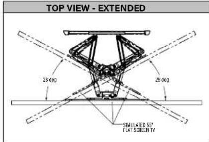
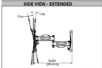
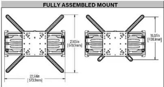
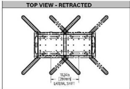
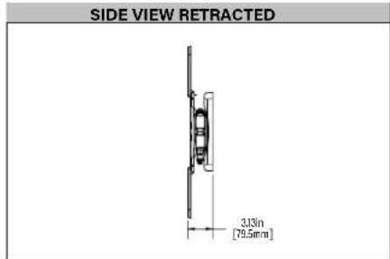
Dimensions

STEP1 Attach TV Bracket to TV
WARNING: This product contains small items that could be a choking hazard if swallowed.
Before starting assembly, verify all parts are included and undamaged. If any parts are missing or damaged, do not return the damaged item to your dealer; contact Customer Service. Never use damaged parts!

NOTE: Not all hardware included will be used.
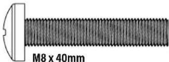
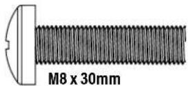
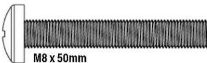
STEP1 Parts and Hardware

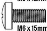
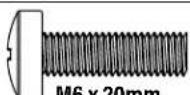
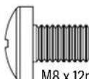
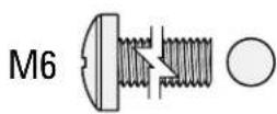
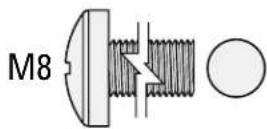
TV Screws (qty. 4 each)
[Only one size fits your TV]
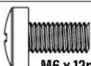
M6
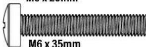
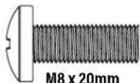
M8
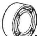
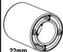
Spacers
(qty. 4 each)
[If necessary]

2.5mm
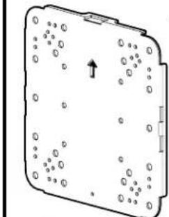

TV Bracket
qty.1
05
qty.4

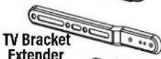
Short Extender

qty.2
TV Bracket
Screw

qty.8
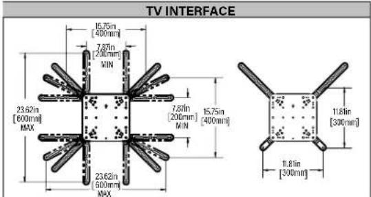
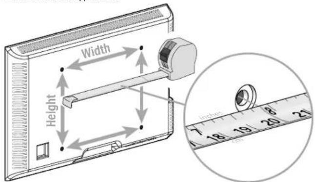
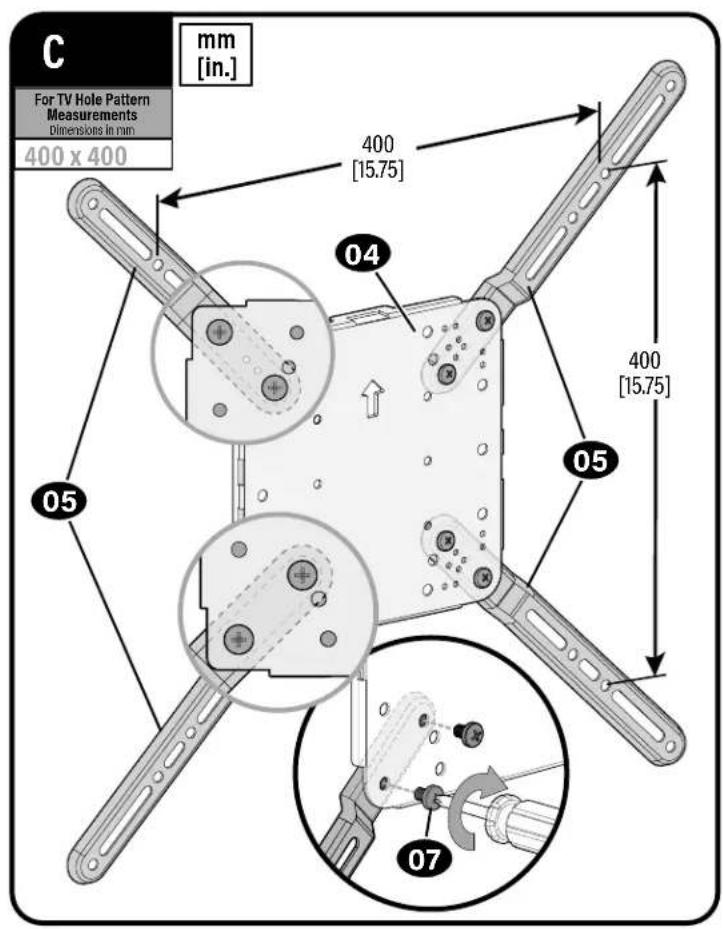
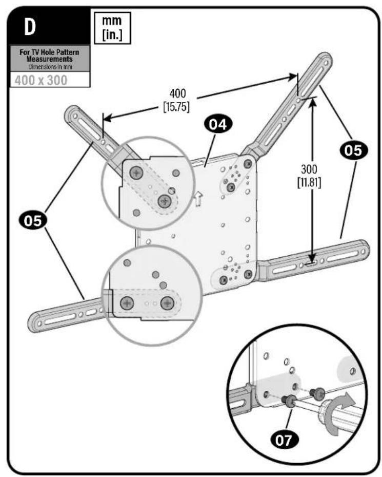
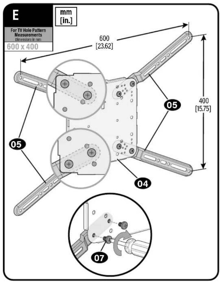
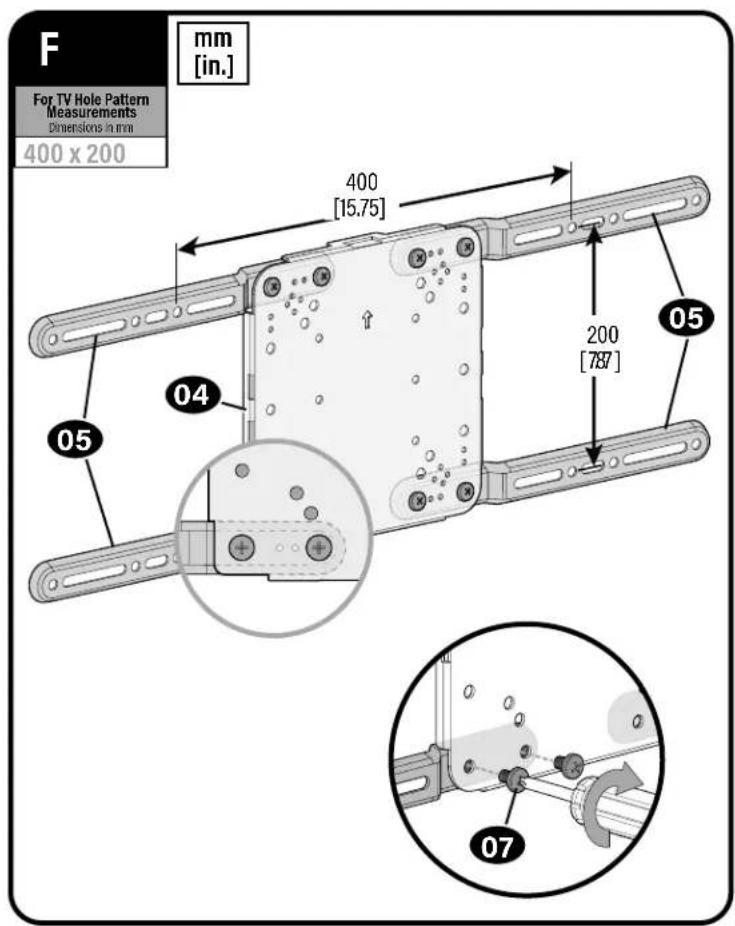
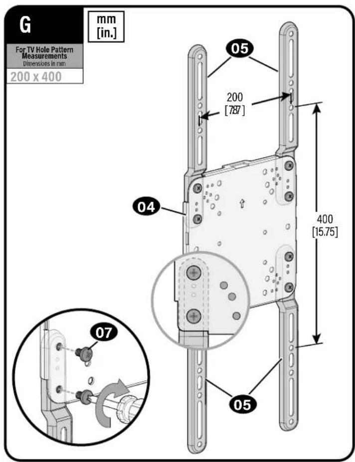
1.1 Measure Your TV Hole Pattern
Measure the width and height of your TV hole pattern in mm.
Record your measurements:
Width mm x Height mm
| inch | cm | mm |
| 4 | 10 | 100 |
| 7 % | 20 | 200 |
| 11 % | 30 | 300 |
| 15 % | 40 | 400 |
| 23 % | 60 | 600 |
inch dimensions are approximate
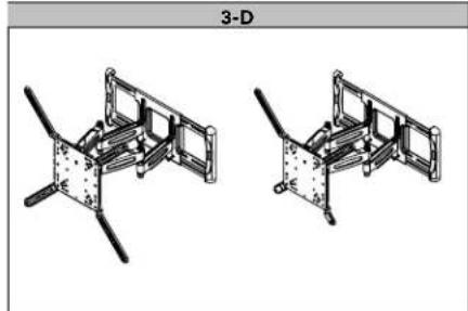
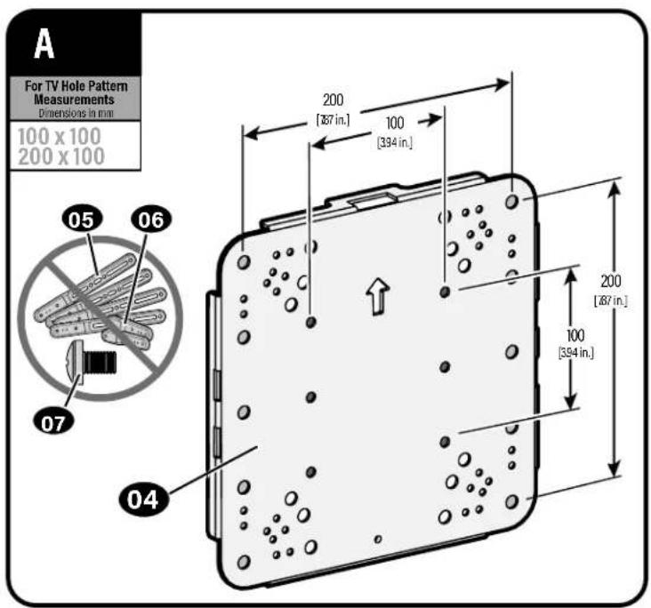
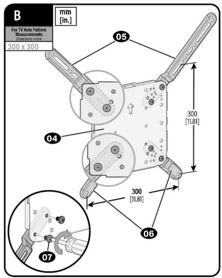
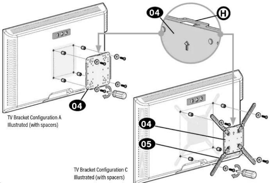
1.2 Assemble Your TV Bracket
Based on your TV hole pattern measurements, determine which TV bracket configuration to use, A, B, C, D, E, F or G.
1.3 Select TV Screw Diameter
Only one screw size fits your TV.
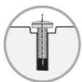
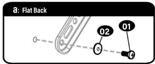
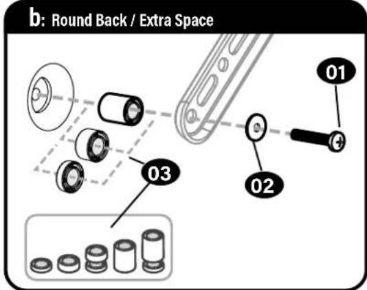
1.4 Select TV Screw Length
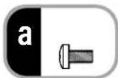
a:For flat-back TVs, no spacers 03 required.
b: Spacers 03 supplied for:
Round (irregular) back TVs
TVs with inset mounting holes
- Extra space needed for cables

FLAT BACK ROUND/BACK CABLES INSERT HOLES
Standard configurations are shown. For special applications, or if you are uncertain about your hardware selection, contact Customer Service.
CAUTION:
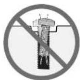
Verify adequate thread engagement with your screw/washer/spacer combination AND TV bracket. - Too short will not hold the TV. - Too long will damage the TV.
Too Short
Too Long
1.5 Attach TV Bracket
Position your TV bracket configuration (A, B, C, D, E or F) onto your TV, making sure the bracket is both centered and level over your TV hole pattern.

NOTE: The hanging tab H on faceplate 04 must be oriented toward the top of the TV.
Secure the TV bracket using your selection: (a) screw/washer or (b) screw/washer/spacer.

CAUTION: Avoid potential personal injuries and property damage! DO NOT use power tools for this step.
Tighten the screws only enough to secure the TV bracket to the TV. DO NOT overtighten the screws.
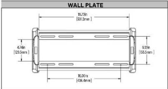
STEP 2 Attach Wall Plate to Wall
WARNING: This product contains small items that could be a choking hazard if swallowed.
Before starting assembly, verify all parts are included and undamaged. If any parts are missing or damaged, do not return the damaged item to your dealer; contact Customer Service. Never use damaged parts!
NOTE: Not all hardware included will be used.
STEP 2 Parts and Hardware
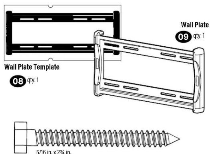
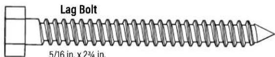
in. x2% in.
Lag Screw

qty.4
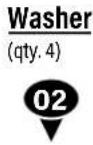
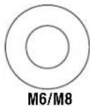
Washer
11 qty.4
Concrete Installation Kit CMK1 is NOT INCLUDED
Contact Customer Service to inquire about the additional hardware.

Lag Bolt Washer

5/16 in.
For concrete installations ONLY

CAUTION: Do not use in drywall or wood
Concrete Anchor

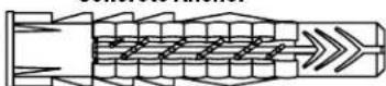
Fischer UX10 x 60R Anchor
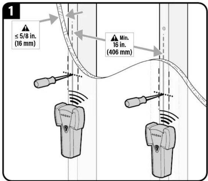
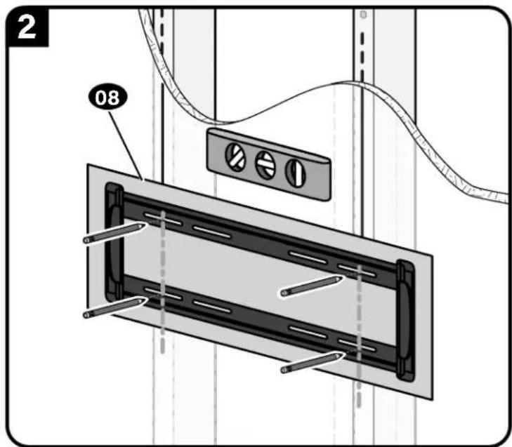
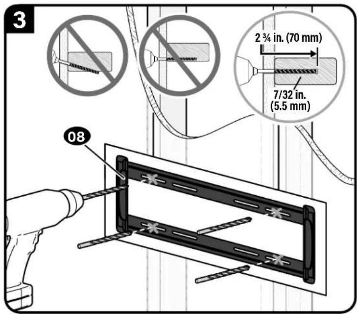
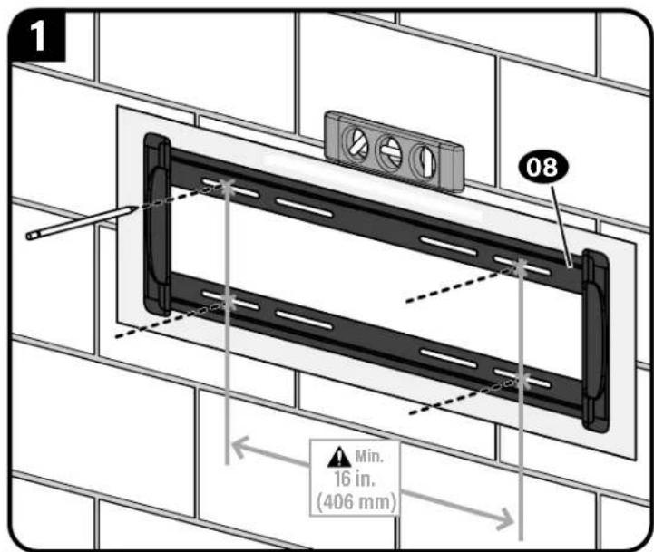
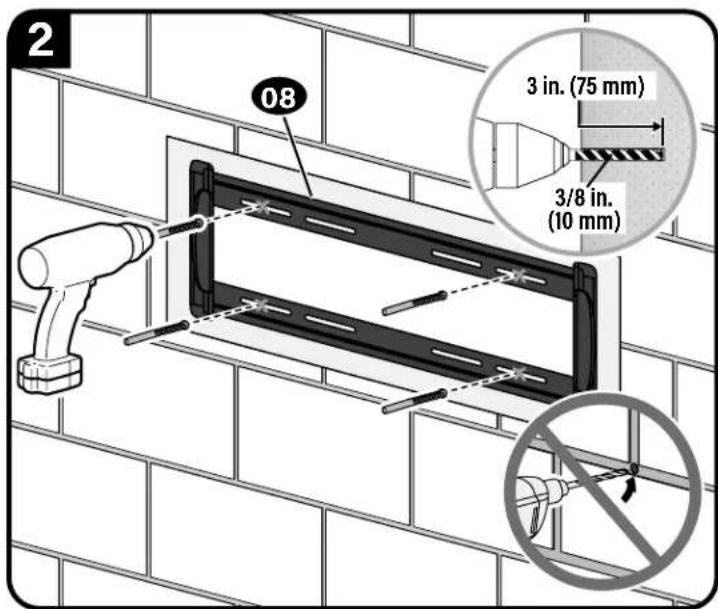
STEP 2A Attach Wall Plate to Wall
Wood Stud Option

UITION: Avoid potential personal injury or property damage!
- Drywall covering the wall must not exceed 5/8 in. (16 mm)
Minimum wood stud size: nominal 2 × 4 in. (51 x 102 mm) actual 112 × 312 in. (38 x 89 mm)
Minimum horizontal space between lag bolts: 16 in. (406 mm)
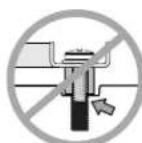
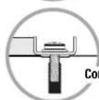
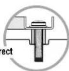
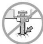
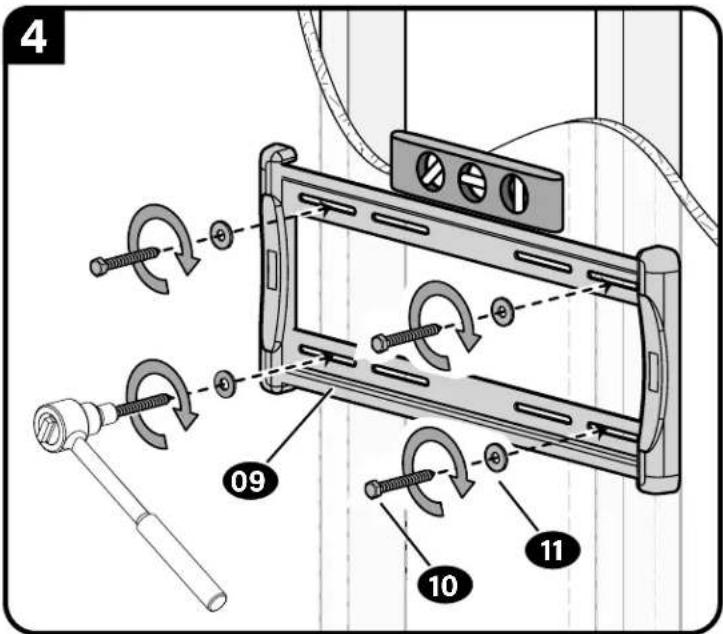
CAUTION: Avoid potential personal injury or property damage!
Improper use could reduce the holding power of the lag bolt 10
Tighten the lag bolts 10 only until the washers 11 are pulled FIRMLY against the wall plate 09.
DO NOT over-tighten the lag bolts 10
Go to STEP 3 on PAGE 16.
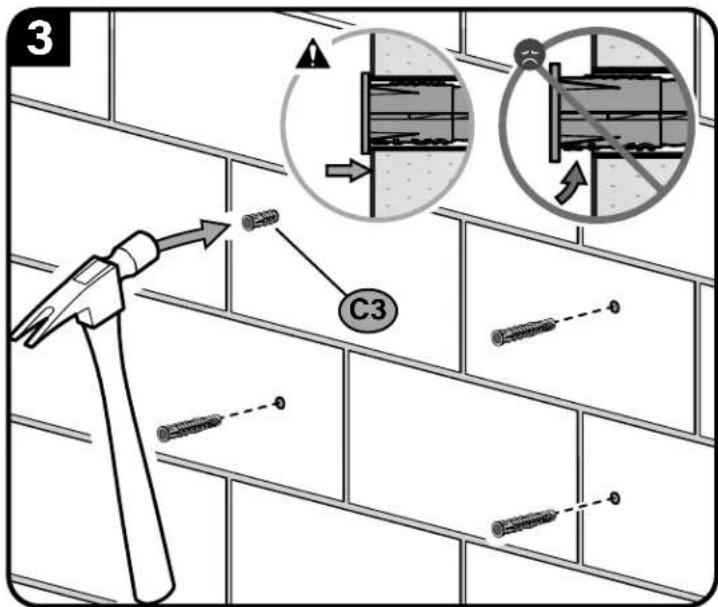
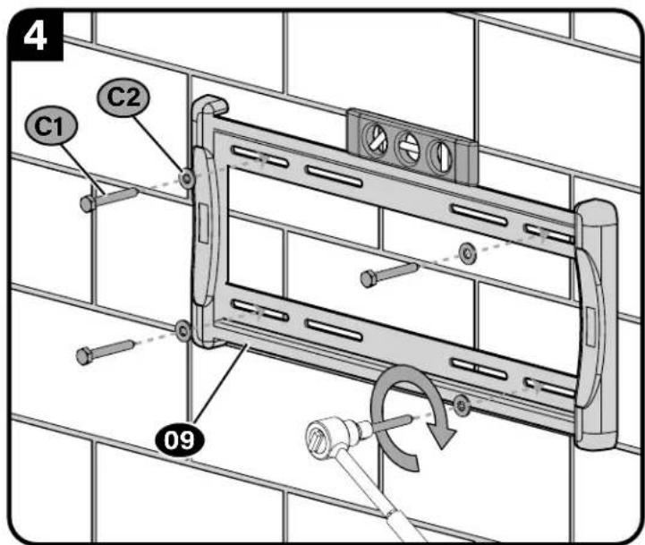
STEP 2B Attach Wall Plate to Wall
Solid Concrete or Concrete Block Option
AUTION: Avoid potential personal injury or property damage!
- Mount wall plate 09 directly onto concrete surface (no wall covering)
Minimum solid concrete thickness: 8 in. (203 mm)
Minimum concrete block size: 8 × 8 × 16 in. (203 x 203 x 406 mm)
Minimum horizontal space between fasteners: 16 in. (406 mm)
Concrete Installation Kit CMK1 is not included
Contact Customer Service to inquire about the additional hardware.
CAUTION: Avoid potential personal injury or property damage!
Improper use could reduce the holding power of the lag bolt (C1)
Tighten the lag bolts C1 only until the washers C2 are pulled FIRMLY against
the wall plate 09
DO NOT over-tighten the lag bolts C1
Fischer UX10 x 60R C3 - included in the Concrete Installation Kit CMKI).
STEP 3 Hang Your TV
STEP 3 Parts and Hardware
Before starting assembly, verify all parts are included and undamaged. If any parts are missing or damaged, do not return the damaged item to your dealer; contact Customer Service. Never use damaged parts!
WARNING: This product contains small items that could be a choking hazard if swallowed.
M5 Wall Plate Screw

M5 TV Interface Screw
M5 x 6mm


Washer
M5

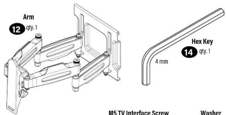
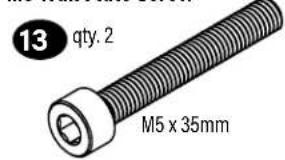
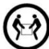
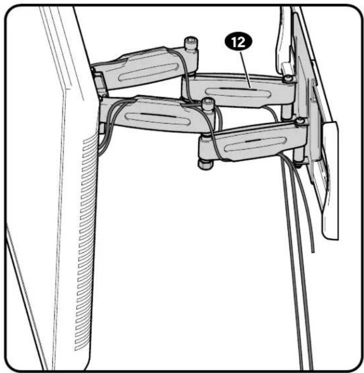
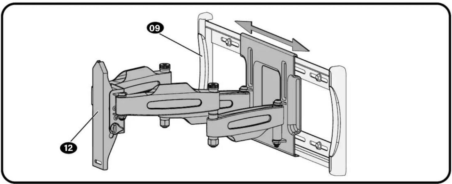
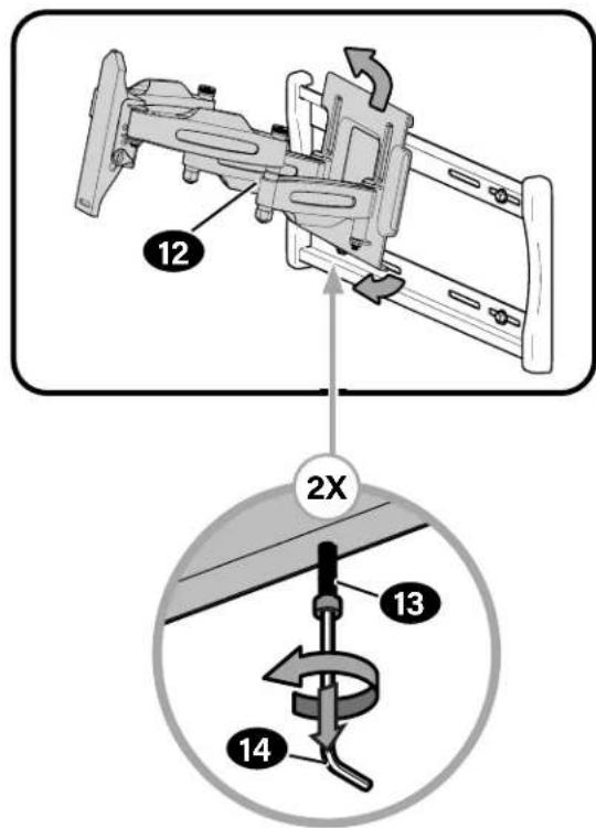
3.1 Attach Arm to Wall Plate

HEAVY! You may need assistance with this step.
CAUTION: Avoid potential injury or property damage!
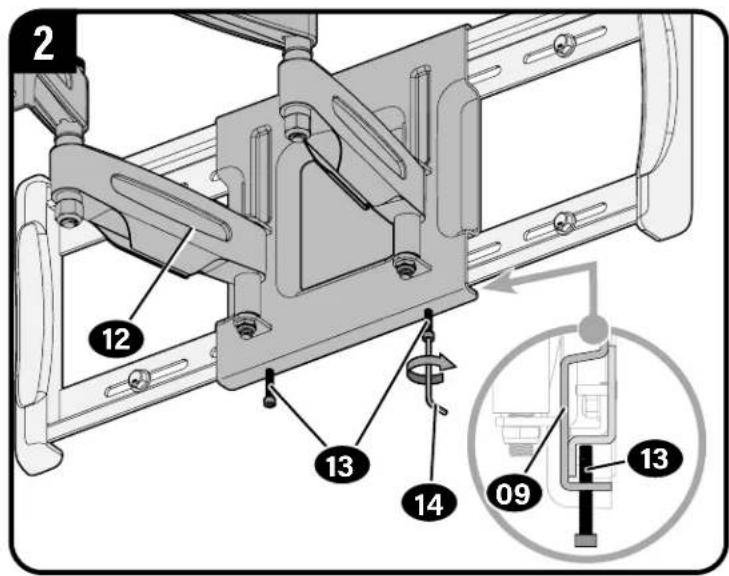
For concrete applications, the base of the arm must remain centered in the wall plate.
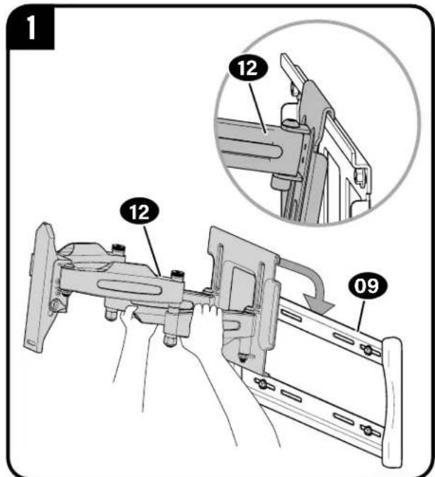
NOTE: When mounting to wood stud walls, the arm 12 can be adjusted within the wall plate 09 for optimal positioning.
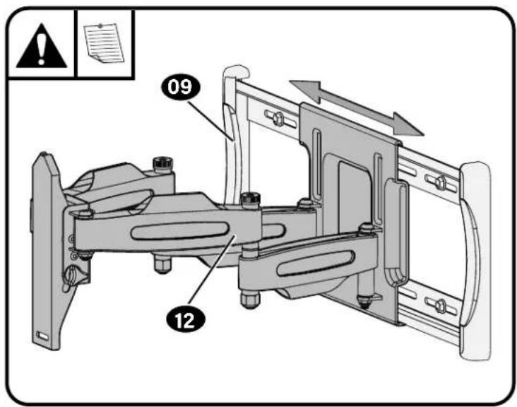
CAUTION: Avoid potential injury or property damage! Screws 13 must be installed to secure the arm 12 to the wall plate 09.
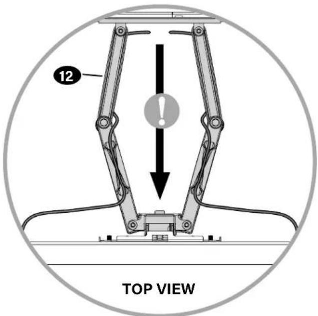
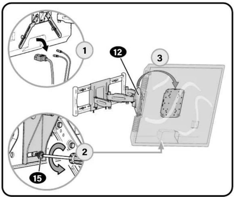
3.2 Hang TV onto Arm
HEAVY! You may need assistance with this step.
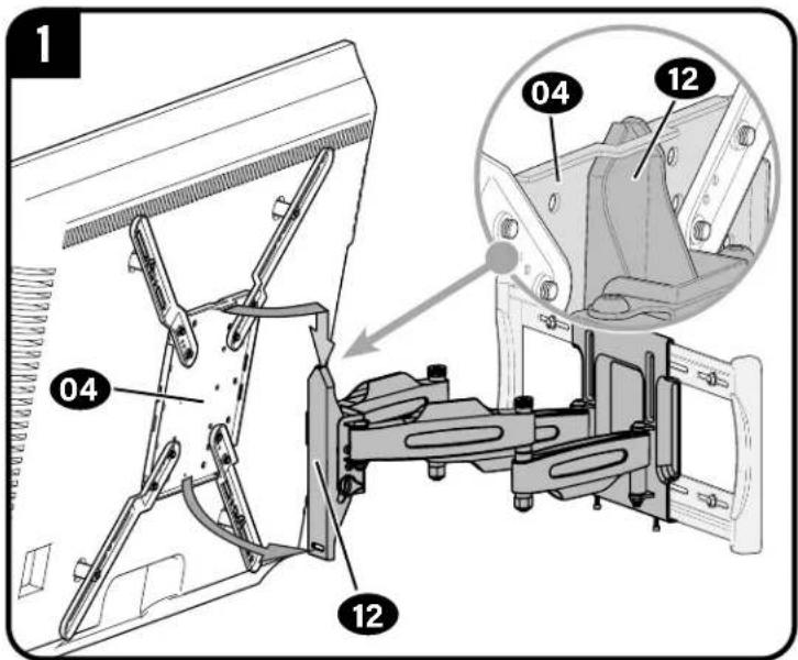
CAUTION! Avoid potential injury or property damage!
This screw 15 and washer 16 must be installed to secure the TV onto arm 12.
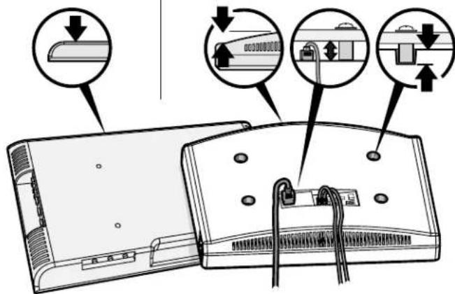
Manage Cables
IMPORTANT: Fully extend arm assembly 12 to ensure you have enough slack in the cables to prevent binding.
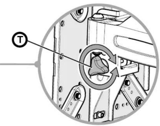
TV Adjustments
TILT ADJUSTMENT
Your TV should adjust easily when moved, then stay in place.
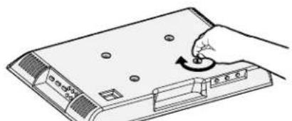
If your TV is too loose or too tight, adjust the tilt tension knob

NOTE: Once your TV is in place, tighten the tilt tension knob to prevent unwanted movement.
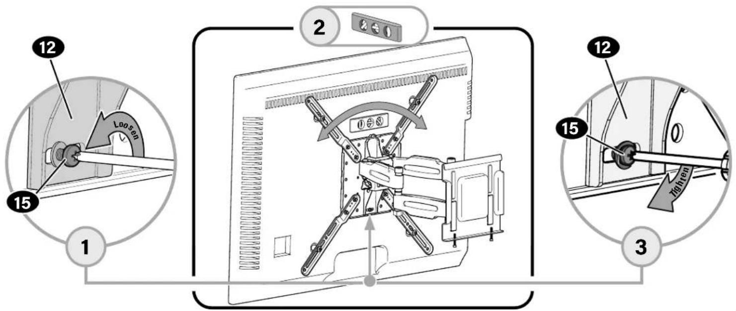
LEVEL ADJUSTMENT
To adjust the leveling of your TV, loosen the screw 15, level your TV, then tighten screw 15.
CAUTION! Screw 15 must be installed to secure the TV onto the arm 12.
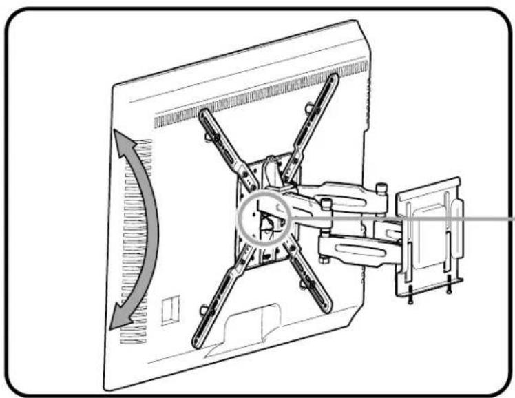
SIDE-TO-SIDE
CAUTION: Avoid potential injury or property damage!
For concrete applications, the base of arm 12 MUST remain centered in the wall plate 09.
For wood stud ONLY: The arm 12 can be adjusted within the wall plate 09 for optimal positioning.
REMOVING THE TV REMOVING THE ARM

HEAVY! You may need assistance with this step.
ESPANOL
PAS01Fijarlaplacalfrontalaltelevision
ver páglina 4
6436 City West Parkway
Eden Prairie, MN 55344 USA
US: +1 (800) 359-5520
SANUS.com
Legrand AV Netherlands B.V.
Franklinstraße 14
6003 DK Weert Netherlands
UK: +44 (0) 800 056 2853
EMEA: +31 (0) 495 580 852
SANUS.com
Authorized Representative for the UK
Starline Holding Technology Ltd.
Unit C Island Road
Reading RG2 ORP UK
leg t i t t t t t t t t t t t t t t t t t t t t t t t t t t t t t t t t t t t t t t t t t t t t t t t t t t 0
©2021 Legrand AV Inc. All Rights Reserved. SANUS is a brand of Legrand. SANUS and the SANUS logo are registered trademarks of Legrand. Amazon, Fire TV and all related logos are trademarks of Amazon.com, Inc. or its affiliates.
Legrand AV Inc. - 6436 City West Parkway - Eden Prairie, MN 55344 USA
6901-603051 00