LLF122 - TV Stand SANUS - Free user manual and instructions
Find the device manual for free LLF122 SANUS in PDF.

| Product Type | TV Stand |
| Brand | Sanus |
| Model | LLF122 |
| Dimensions (W x D x H) | 42 \" x 18 \" x 24 \" |
| Weight Capacity | 100 lbs |
| Material | Safety-tempered glass and steel frame |
| Number of Shelves | 2 |
| Cable Management | Yes, with removable back panel |
| Color | Black |
| Product Weight | 30 lbs |
| Assembly Required | Yes, with included tools |
| Maximum TV Size | 65 inches |
| Warranty | 5 years |
| Country of Origin | China |
| Mounting Type | Freestanding floor stand |
| Cleaning Instructions | Wipe with a soft, damp cloth; do not use abrasive cleaners |
| Recommended for | Flat-panel TVs up to 65\" |
| VESA Compatible | Not applicable to stand type |
| Leveling Feet | Yes, adjustable |
| Spare Parts Available | Yes, through manufacturer |
Frequently Asked Questions - LLF122 SANUS
User questions about LLF122 SANUS
0 question about this device. Answer the ones you know or ask your own.
Ask a new question about this device
Download the instructions for your TV Stand in PDF format for free! Find your manual LLF122 - SANUS and take your electronic device back in hand. On this page are published all the documents necessary for the use of your device. LLF122 by SANUS.
USER MANUAL LLF122 SANUS
natural_image
Technical line drawing of a mechanical assembly with two vertical supports and internal beams (no text or symbols)WE'RE HERE TO HELP

natural_image
Person holding a video player icon with play button overlay (no text or symbols)
Watch it now at: SANUS.com/2849
Want to watch a video that shows how easy this DIY project will be?


Check it out at: SANUS.com/2850
Get it right the first time. HeightFinder™ shows you where to drill.

natural_image
Group of people in an office setting, no visible text or symbols
Call us at: 1-855-734-7805

CAUTION: IMPORTANT SAFETY INSTRUCTIONS
PLEASE READ ENTIRE MANUAL PRIOR TO USE — SAVE THESE INSTRUCTIONS
Please read through these instructions completely to be sure you're comfortable with this easy install process.
Check your TV owner's manual to see if there are any special requirements for mounting your TV.
If you do not understand these instructions or have doubts about the safety of the installation, assembly or use of this product, contact Customer Service: 1-855-734-7805.
CAUTION: Avoid potential personal injuries and property damage!
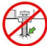
- This product is designed ONLY to be installed into wood studs, solid concrete or concrete block.
— DO NOT INSTALL INTO DRYWALL ALONE — DRYWALL ALONE WILL NOT HOLD THE WEIGHT OF YOUR TV. - This product is designed for INDOOR USE ONLY.
- The wall must be capable of supporting five times the weight of the TV and mount combined.
- Do not use this product for any purpose not explicitly specified by manufacturer.
● Manufacturer is not responsible for damage or injury caused by incorrect assembly or use.
TV Weight Limit
(including accessories)
DO NOT EXCEED
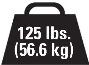

CAUTION:
DO NOT exceed the
maximum weight indicated. This mounting system is intended for use only with the maximum weights indicated. Use with products heavier than the maximum weights indicated may result in collapse of the mount and its accessories, causing possible injury.
If your TV (plus accessories) weighs MORE, this mount is NOT compatible.
Visit MountFinder.Sanus.com or call customer service to find a compatible mount.
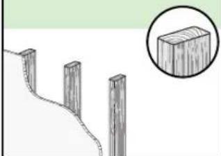
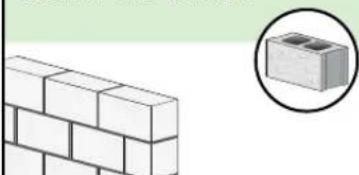
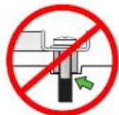
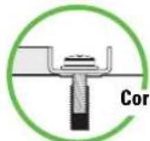
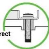
Wall Construction
ONLY install on these acceptable wall types.
CAUTION:
DO NOT
install in drywall alone

Drywall alone will NOT hold the weight of your TV
wood studs Solid concrete or concrete block
natural_image
Illustration of wooden posts on a hillside with a magnified inset showing a rectangular block (no text or symbols)ACCEPTABLE
natural_image
Illustration of a brick wall next to a magnified inset showing a small block (no text or symbols)ACCEPTABLE
Concrete kit CMK1 is required [NOT INCLUDED] Call Customer Service

Unsure
Call Customer Service: 1-855-734-7805
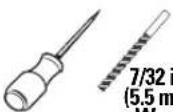
Tools Needed
Tape Measure
Pencil
Level

Tape
Screwdriver
Electric Drill
Socket Wrench
Wood Stud Install
Stud Finder
Awl
7/32 in. (5.5 mm) Wood
Drill Bit
Concrete Install
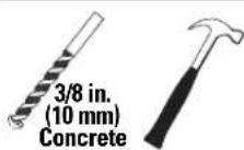
Drill Bit
Hammer
Dimensions
TV INTERFACE
![23.62in [600mm] MAX 7.87in [200mm] MIN 7.87in [200mm] MIN 15.75in [400mm] MAX](/content/2026/05/1063071/images/2274c0869a3ea2ed621abf284f50893e862d8e3337e0d0f32e0ad55445cfbe26.jpg)
3-D
natural_image
Technical line drawing of a mechanical assembly with beams and supports (no text or symbols)WALL PLATE
![15.98in [406mm] 0.87in [22mm] 9.00in [228.5mm] 7.62in [193.5mm] 5.31in [135mm] 5.31in [135mm] [0.35in 9mm]](/content/2026/05/1063071/images/bc0ae5b5d71b0ffc8ab554f26366ab47b2d2cb85f31d4f140f88a4befeac3b10.jpg)
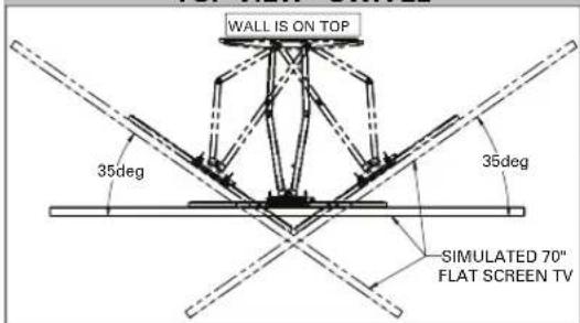
TOP VIEW - SWIVEL
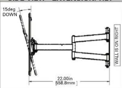
SIDE VIEW - EXTENSION/TILT
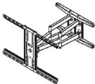
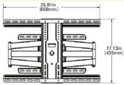
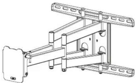
FULLY ASSEMBLED MOUNT
FRONT VIEW - TILT
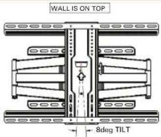
SIDE VIEW - RETRACTED
![9.24in [234.6mm] 7.89in [200.4mm] 2.53in [64.2mm] WALL IS ON RIGHT](/content/2026/05/1063071/images/e121588b4b67fa0924be8311f6f4fb17e19fcbd414ebbab234546a82c5573969.jpg)
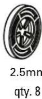
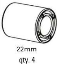
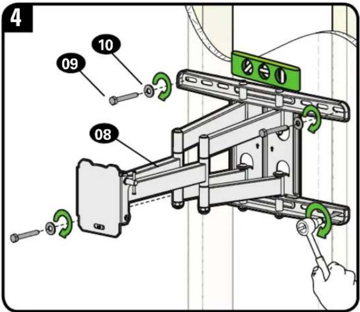
Supplied Parts and Hardware
⚠ WARNING: This product contains small items that could be a choking hazard if swallowed.
Before starting assembly, verify all parts are included and undamaged. If any parts are missing or damaged, do not return the damaged item to your dealer; contact Customer Service. Never use damaged parts!

NOTE: Not all hardware included will be used.
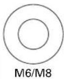
STEP 1 Parts and Hardware

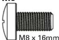
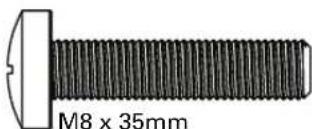
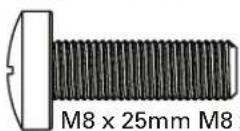
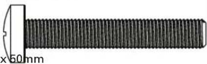
TV Screws
(qty. 4 each)
[Only one size fits your TV]
M6
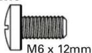
M8
natural_image
Close-up of a black threaded bolt with a white cutting edge, shown with measurement annotation (no text or symbols on the object itself)Washer (qty. 4 each)

Spacers
[If necessary]

Vertical TV Bracket
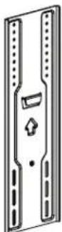
04 qty. 1
Shipped Attached
Wing Nuts
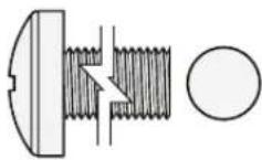
M5
06 qty. 4
natural_image
Pure diagram of a mechanical component with no text, numbers, or symbolsHorizontal TV Bracket

STEP 2 Parts and Hardware
natural_image
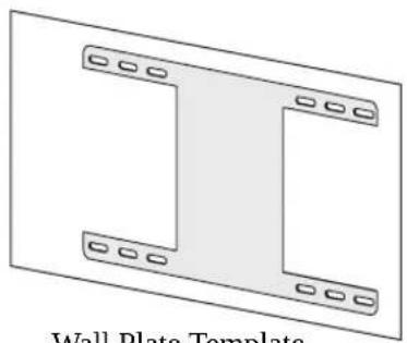
Diagram of a wall plate template with two L-shaped components and mounting holes (no text or symbols)Wall Plate Template
07 qty. 1
natural_image
Technical line drawing of a mechanical assembly with mounting brackets and structural supports (no text or symbols)Wall Plate Assembly
08 qty. 1
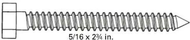
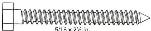
Lag Screw
09 qty. 4
Washer [Lag Screw]
10 qty. 4

5/16 in.
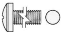
STEP 3 Hardware
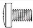
M5 x 8mm
Securement Screw
11 qty. 1

Washer [Securement Screw]
12 qty. 1
Installation / Adjustments
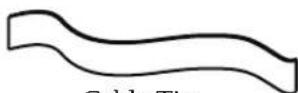
14 qty. 4
Hardware for STEP 2B
Concrete Installation [Concrete Kit CMK1 is NOT INCLUDED]
Contact Customer Service to inquire about the Concrete Installation Kit CMK1.
For concrete installations ONLY

CAUTION: Do not use in drywall or wood
Concrete Anchors

qty. 4
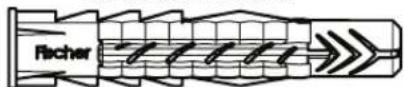
Fischer UX10 x 60R
Washer

qty. 4

5/16 in.
Lag Bolt

qty. 4
STEP 1 Attach TV Bracket to TV
1-1 Select TV Screw Diameter
Hand thread screws into the threaded inserts on the back of your TV to determine which screw diameter (M6, or M8) to use.
M6
M8

natural_image
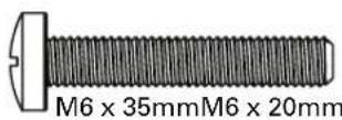
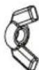
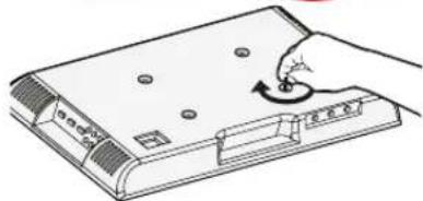
Illustration of a hand using a rotary knob to press down a device (no text or symbols visible)1-2 Select TV Screw Length
a: For flat-back TVs, no spacers 03 required.

FLAT BACK
b: Spacers 03 supplied for:
• Round (irregular) back TVs
- Extra space needed (for cables or inset mounting holes)

ROUND BACK
If your TV included inset spacers or wall mount adapters, use them UNDER the mount hardware.
CAUTION:
Verify adequate thread engagement with the screw or screw/spacer combination.
- Too short will not hold the TV.
- Too long will damage the TV.
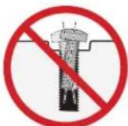
Too Short
Too Long
1-3 Attach TV Bracket
| inches | cm | mm |
| 7 1⁄8 20 200 | ||
| 11 3⁄4 30 300 | ||
| 15 3⁄4 40 400 | ||
| 23 3⁄4 60 600 |
inch dimensions are approximate
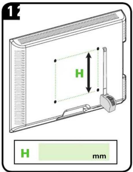
Measure the HEIGHT (H) of your TV's mounting hole pattern.
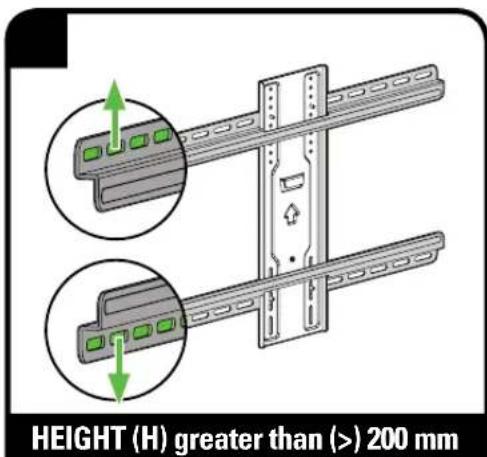
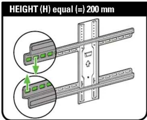

NOTE: Position the slotted holes as wn for your TV hole pattern Height (H).
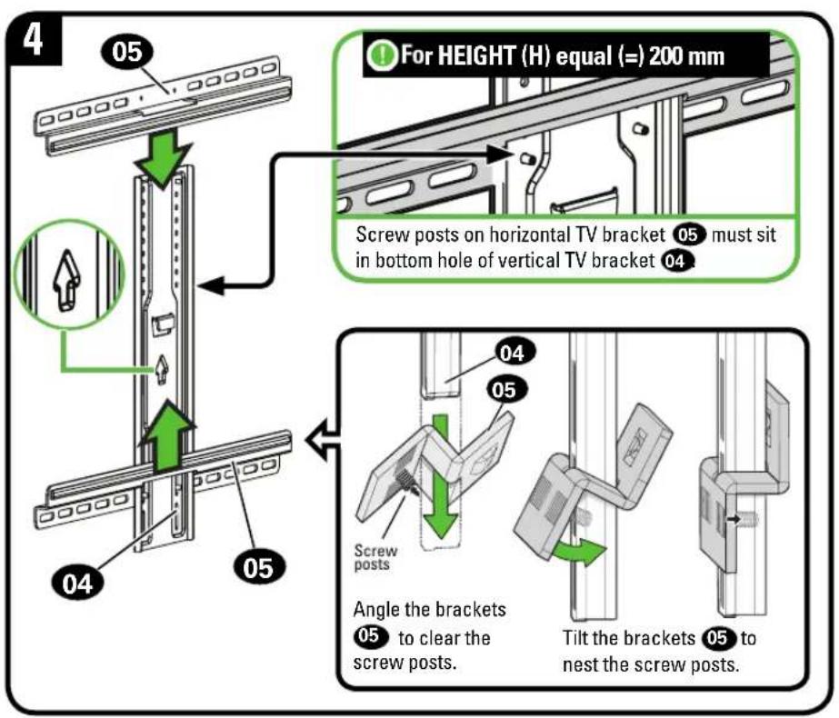
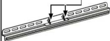
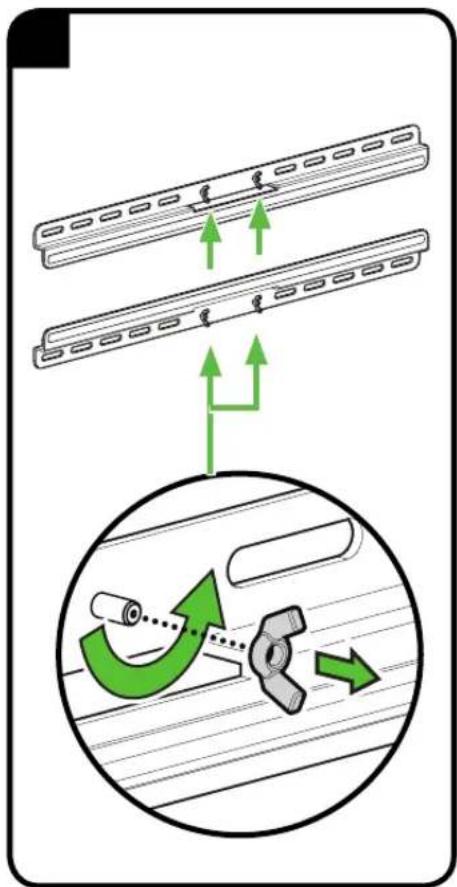
Slide horizontal TV brackets 05 onto the vertical TV bracket 04 as shown.
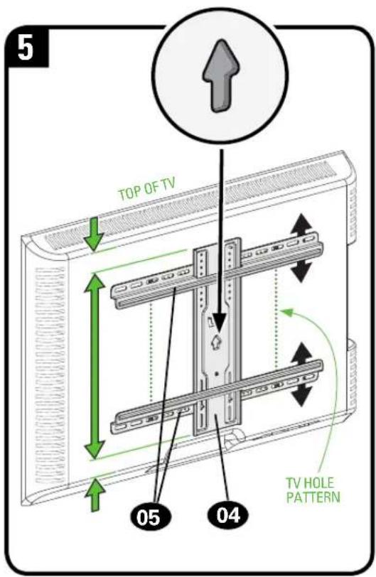
Center the TV brackets 04 and 05 over the hole pattern on your TV.
NOTE: If the TV brackets are not centered, you may need to reposition to align properly (see previous step).
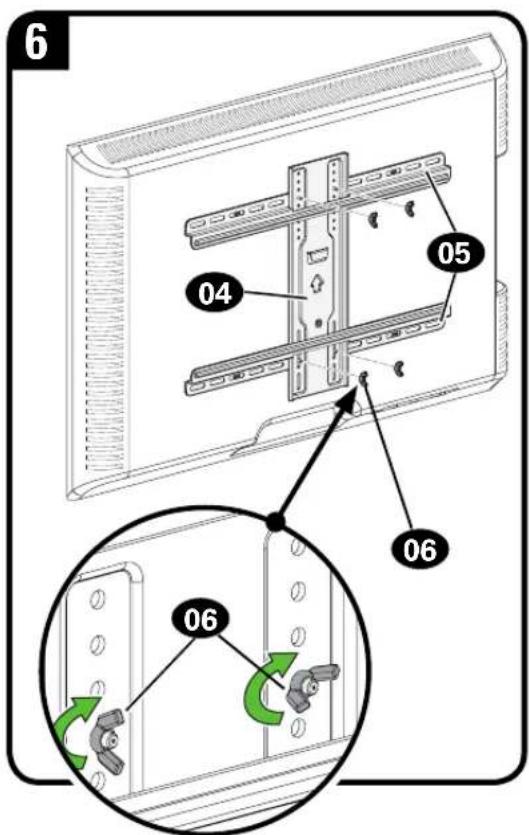
Secure the assembly with the four wing nuts 06.
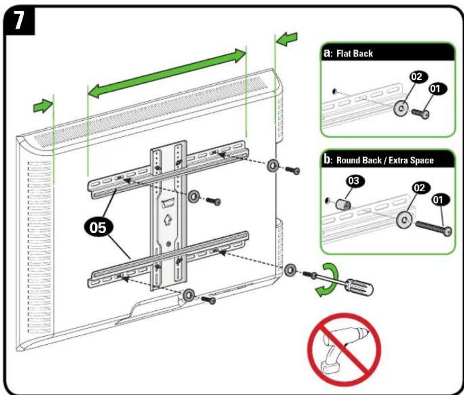
Center the TV bracket assembly over your TV's hole pattern and attach using screw combination a or b you selected for your TV.
CAUTION: Avoid potential personal injuries and property damage! DO NOT use power tools for this step. Tighten the screws 01 only enough to secure the TV brackets to the TV.
STEP 2A Attach Wall Plate
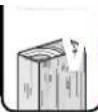
Food Stud Installation
CAUTION: Avoid potential personal injury or property damage!
- Drywall covering the wall must not exceed 5/8 in. (16 mm)
● Minimum wood stud size: nominal 2 x 4 in. (51 x 102 mm) actual 1 ½ x 3 ½ in. (38 x 89 mm)
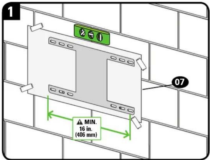
• Minimum horizontal space between fasteners: 16 in. (406 mm)
• Stud centers must be verified
Locate studs. Verify the center of the stud(s) using an awl, a thin nail, or an edge to edge stud finder.
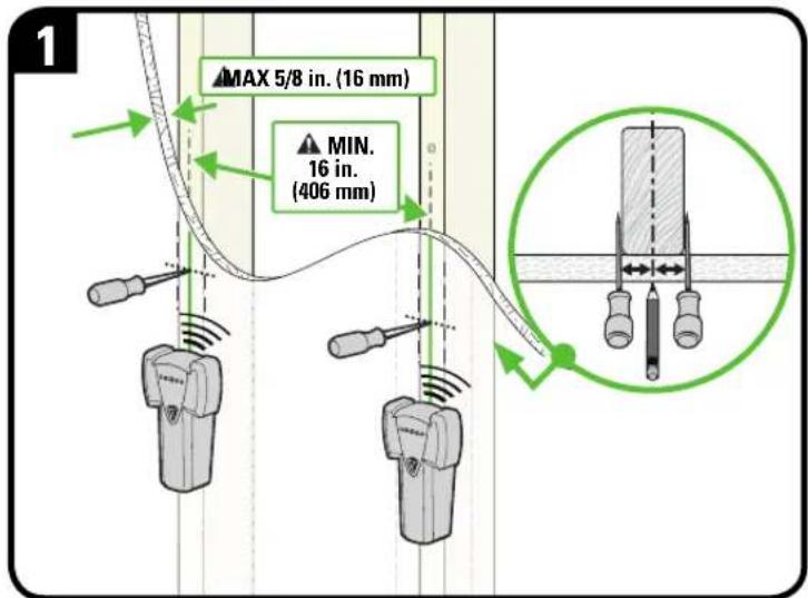
Level the wall plate template 07 and align the hole pattern over the center of your studs, then tape in place.
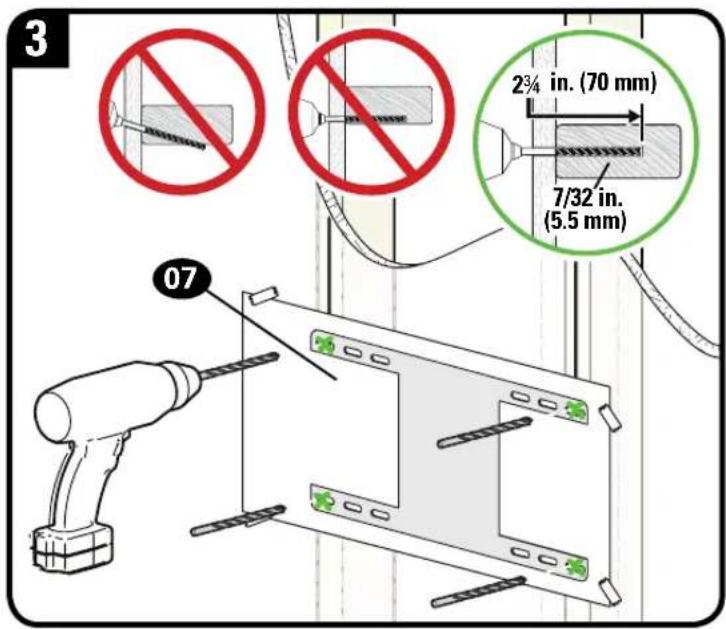
Drill pilot holes then remove the wall plate template 07.
IMPORTANT: Be sure to drill into the center of the stud.
IMPORTANT: Pilot holes must be drilled to a depth of 2 34 in. (70 mm), using a 7/32 in. (5.5 mm) diameter drill bit.
Install the wall plate 08 using four lag bolts 09 and washers 10. Tighten all lag bolts only until they are pulled firmly against the wall plate.
CAUTION: Improper use could reduce the holding power of the lag bolt. DO NOT over-tighten the lag bolts.
Go to STEP 3 on PAGE 16.
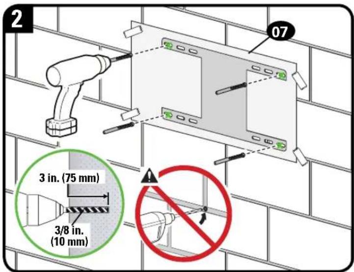
STEP 2B Attach Wall Plate

Solid Concrete or Concrete Block Installation

CAUTION: Avoid potential personal injury or property damage!
- Mount the wall plate assemb08 directly onto the concrete surface
• Minimum solid concrete thickness: 8 in. (203 mm)
● Minimum concrete block size: 8 x 8 x 16 in. (203 x 203 x 406 mm)
• Minimum horizontal space between fasteners: 16 in. (406 mm)

Concrete Install Kit #CMK1 is not included
(see page 7) Contact Customer Service at 1-855-734-7805 to inquire about the Concrete Installation Kit CMK1.
Level the wall plate template 07 and tape in place.
Drill four pilot holes.
CAUTION: Never drill into the mortar between blocks.
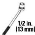
IMPORTANT: Pilot holes must be drilled to a depth of 3 in. (75 mm), using a 3/8 in. (10 mm) diameter drill bit.
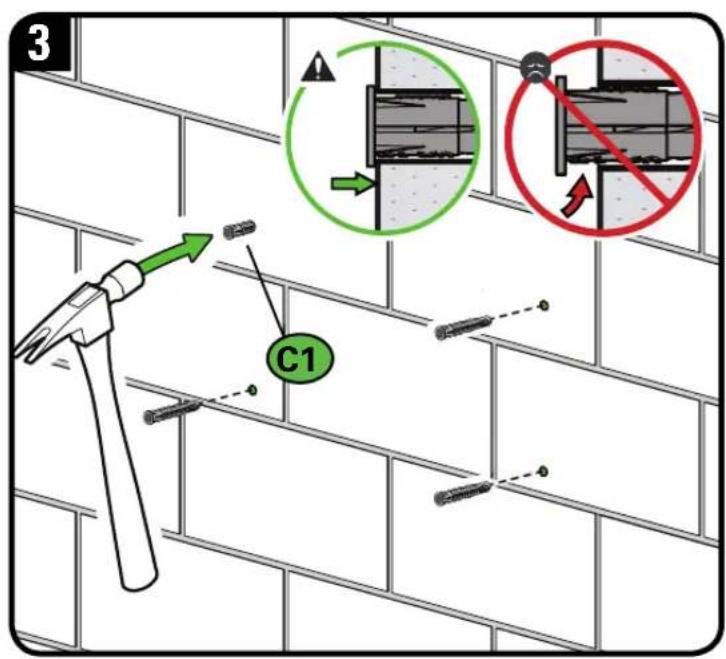
Remove wall plate template 07 and insert four concrete anchors C1.
CAUTION: Be sure the anchors are seated flush with the concrete surface.
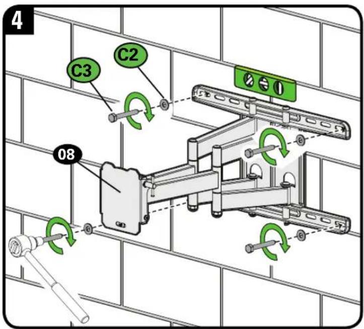
Install the wall plate 08 using four lag bolts C3 and washers C2. Tighten all lag bolts only until they are pulled firmly against the wall plate.
⚠️ CAUTION: Improper use could reduce the holding power of the lag bolt. DO NOT over-tighten the lag bolts.
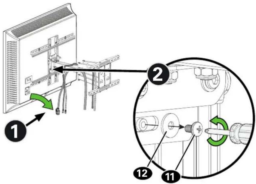
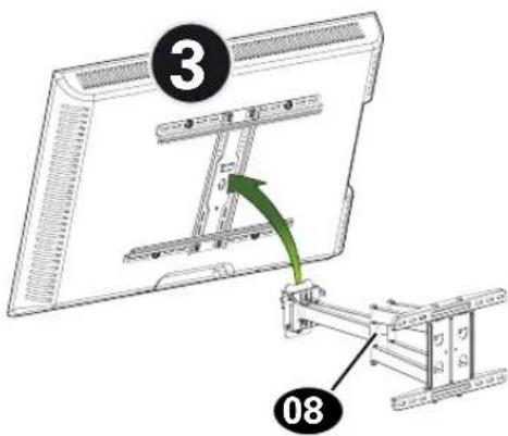
STEP 3 Hang TV onto Wall Plate

HEAVY! You may need assistance with this step.
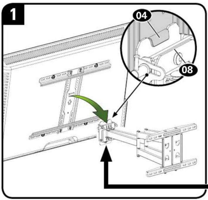
Hang your TV onto the arm of wall plate assembly 08 by first hooking the top support, then resting the TV into place.
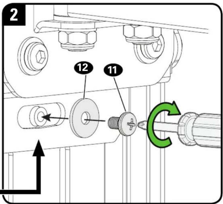
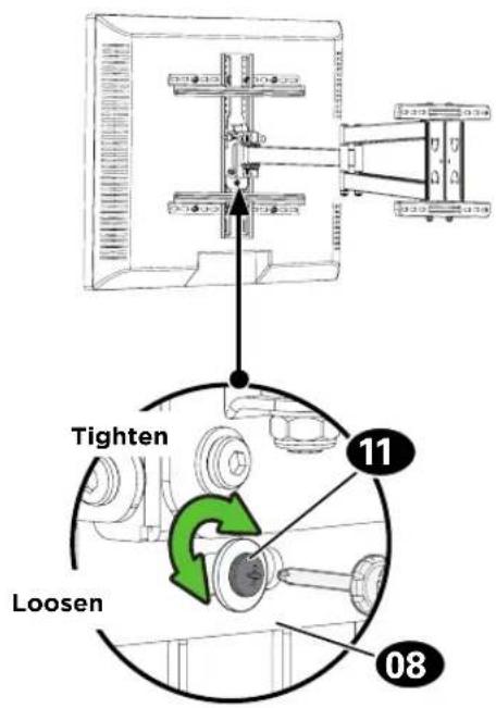
Lock TV to wall plate assembly 08 with screw 11 and washer 12.
CAUTION! Avoid potential personal injuries and property damage! Screw 11 must be installed to secure your TV onto the wall plate assembly 08.
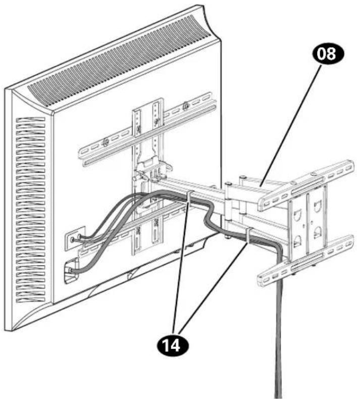
Manage Cables
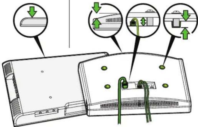
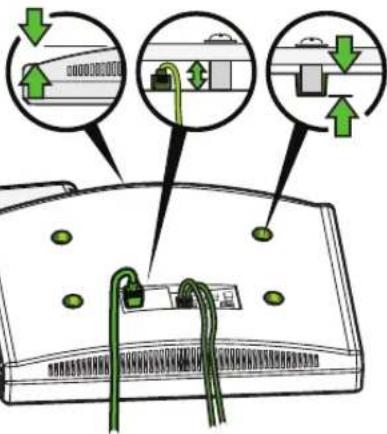
Fully extend the arms before routing cables.
Use cable ties 14 to bundle and attach cables to the arms 08 for a cleaner look.
TV Adjustments
TILT LEVEL
- Loosen the tilt lever T.
- Adjust the TV tilt position.
- Tighten tilt lever Ⓣ to secure the TV in place at your desired tilt angle.
NOTE: If needed, tighten screw T_2 for additional tilt tensioning.
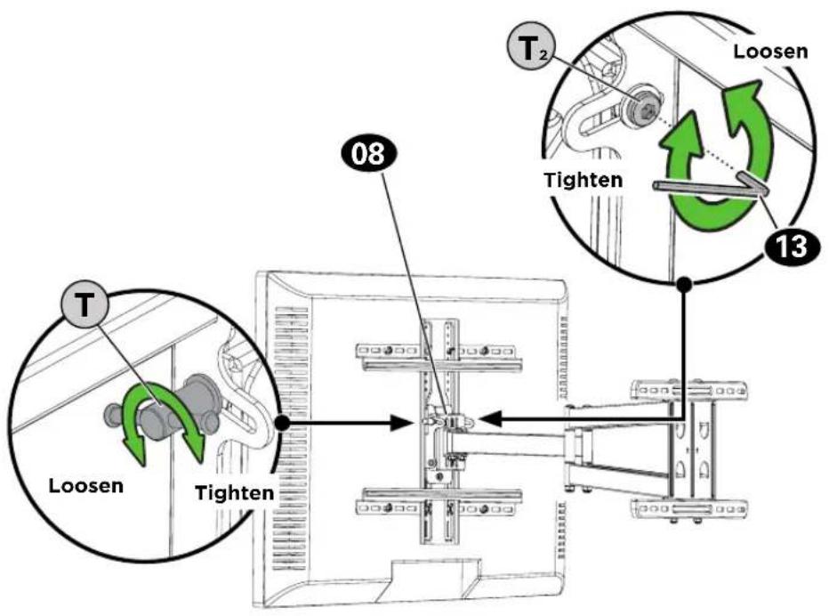
- Loosen the screw 11 on the rear of wall plate assembly 08.
- Level your TV.
- Retighten screw 11 to secure in place.

HEAVY! You may need assistance with this step.
To remove your TV from the wall plate assembly 08:
- Disconnect all cables.
- Remove screw 11 and washer 12.
- Lift the TV up and off of wall plate assembly 08.
ESPAÑOL
Watch the installation video or call our Customer Care team for help

SAN.US/2849 1-855-734-7805

Legrand AV Inc. and its affiliated corporations and subsidiaries (collectively, "Legrand"), intend to make this manual accurate and complete. However, Legrand makes no claim that the information contained herein covers all details, conditions, or variations. Nor does it provide for every possible contingency in connection with the installation or use of this product. The information contained in this document is subject to change without notice or obligation of any kind. Legrand makes no representation of warranty, expressed or implied, regarding the information contained herein. Legrand assumes no responsibility for accuracy, completeness or sufficiency of the information contained in this document.
©2019 Legrand AV Inc. All rights reserved. Sanus is a division of Legrand. SANUS and the SANUS logo are registered trademarks.
Legrand AV Inc. • 6436 City West Parkway • Eden Prairie, MN 55344 USA
6901-602394 00
