LMF219 - TV Stand SANUS - Free user manual and instructions
Find the device manual for free LMF219 SANUS in PDF.

User questions about LMF219 SANUS
0 question about this device. Answer the ones you know or ask your own.
Ask a new question about this device
Download the instructions for your TV Stand in PDF format for free! Find your manual LMF219 - SANUS and take your electronic device back in hand. On this page are published all the documents necessary for the use of your device. LMF219 by SANUS.
USER MANUAL LMF219 SANUS
natural_image
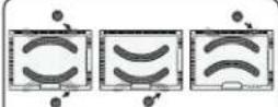
Technical line drawing of a mechanical linkage assembly (no text or symbols)WE'RE HERE TO HELP
natural_image
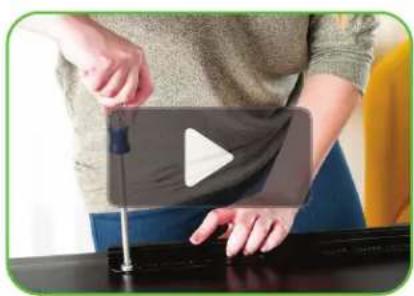
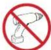
Person using a handheld device to press or install a black object, no visible text or symbolsWant to watch a video that shows how easy this is?
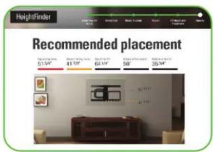
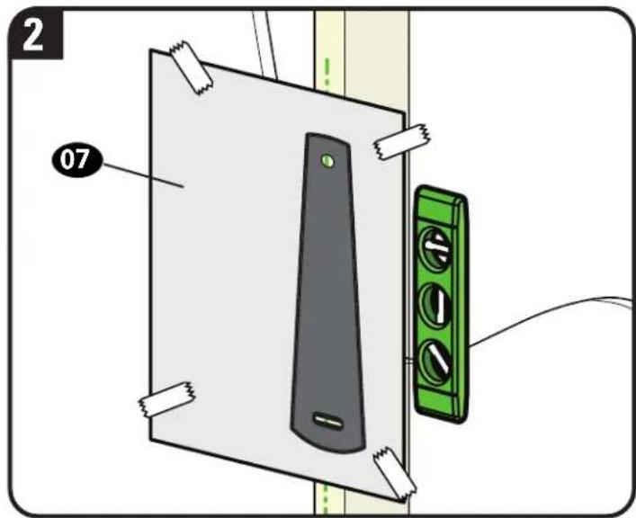
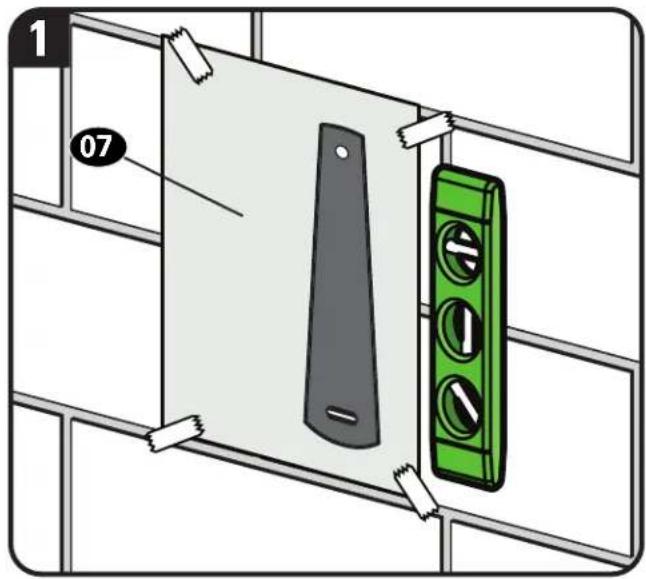
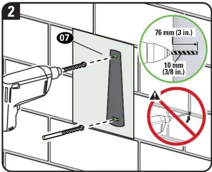
Get it right the first time! HeightFinder™ shows you where to drill.

natural_image
Group of employees in an office setting, one wearing a headset and smiling (no visible text or symbols)Our live, US-based install experts are standing by to help.
Watch it now at: SANUS.com/3064

Use it now at: SANUS.com/2850

Call us at: 1-855-734-7805
IMPORTANT SAFETY INSTRUCTIONS
PLEASE READ MANUAL PRIOR TO USE – SAVE THESE INSTRUCTIONS
Please read through these instructions completely to be sure you're comfortable with this easy install process.
Check your TV owner's manual to see if there are any special requirements for mounting your TV.
If you do not understand these instructions or have doubts about the safety of the installation, assembly or use of this product, contact Customer Service 1-855-734-7805.

CAUTION: Avoid potential personal injuries and property damage!
- This product is designed ONLY to be installed into wood studs, solid concrete or concrete block.
— DO NOT INSTALL INTO DRYWALL ALONE — DRYWALL ALONE WILL NOT HOLD THE WEIGHT OF YOUR TV.
• This product is designed for INDOOR USE ONLY. - The wall must be capable of supporting five times the weight of the TV and mount combined.
- Do not use this product for any purpose not explicitly specified by manufacturer.
- Manufacturer is not responsible for damage or injury caused by incorrect assembly or use.
TV Weight Limit
(including accessories)
DO NOT EXCEED
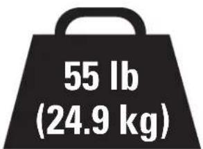
If your TV (including accessories) exceeds this weight, this mount is NOT compatible.
Visit SANUS.com or call customer service to find a compatible mount.
1-855-734-7805
Wall Construction
ONLY install on these acceptable wall types.
Unsure?
Call Customer Service 1-855-734-7805

CAUTION:
DO NOT install in drywall alone
Drywall alone will NOT hold the weight of your TV.
Wood studs
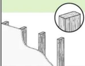
natural_image
Diagram of a wooden fence with four posts and a magnified inset showing a rectangular block (no text or symbols)Perfect!
Solid concrete or concrete block
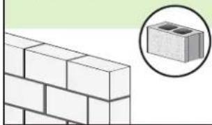
natural_image
Illustration of a brick wall with a magnified inset showing a small block (no text or symbols)Concrete Anchor Kit #CMK1 is required (not included)
Contact Customer Service to inquire about the CMK1 Concrete Anchor Kit.
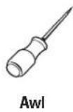
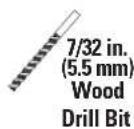
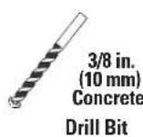
Tools Needed

ScrewdriverTape
Electric Drill
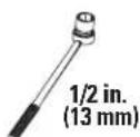
Socket Wrench
Measure
Wood Stud Install

Concrete Install
Dimensions
TV INTERFACE
![15.75 in MAX [400mm] MAX 15.75 in [400mm] 2.95 in [75mm] MIN 2.95 in [75mm] MIN](/content/2026/05/1044048/images/24191865b0854496dd3384f2887c4435d9faacad64f2edc2c49bf8f9e1e56958.jpg)
3-D
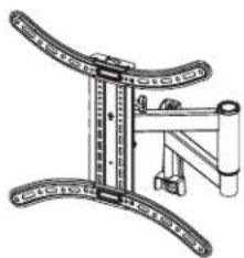
natural_image
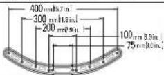
Mechanical assembly diagram showing a frame with curved arms and a vertical rod (no text or symbols)WALL PLATE
![8.21 in [208.5mm] 6.89 in [175.1mm] 2.14 in [54.4mm]](/content/2026/05/1044048/images/c44a0c9104fb847b938ab0040c1cb925ff9d8c128f21b052aaa8facb410d3b7c.jpg)
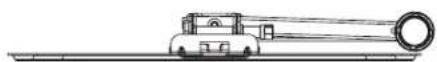
TOP VIEW - EXTENDED
SIDE VIEW - EXTENDED
![5° UP 15° DOWN 19.09 in [484.9mm]](/content/2026/05/1044048/images/1938bca534da6e033c414b156b938f0857a07ff2e471676445c8f13230036142.jpg)
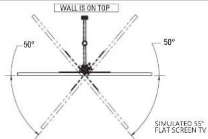
FULLY ASSEMBLED MOUNT TOP VIEW - RETRACTED
![17.85 in [453.4mm] 19.30 in [490.3mm]](/content/2026/05/1044048/images/19c4ba72714636b4e58bc0f72d5815133b40b69f0ccb829e06af9c5ac5b0bfff.jpg)
WALL IS ON TOP
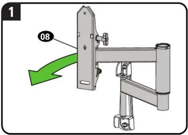
from your TV — if attached.
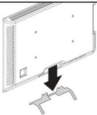
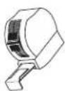
natural_image
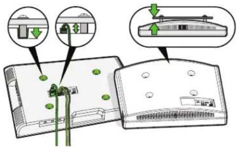
Diagram showing a device with a black arrow pointing to a mechanical component (no text or symbols present)Install any accessories
you may have purchased, if they require TV removal prior to assembly. The TV is removable for future accessory purchases.
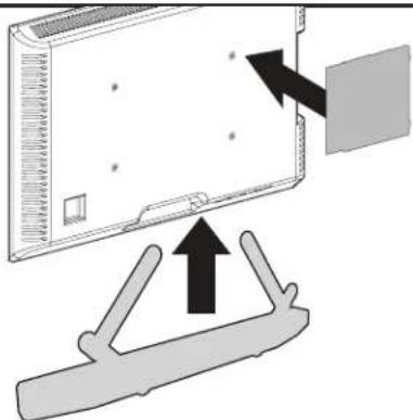
natural_image
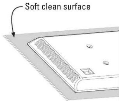
Diagram showing a device with an arrow pointing to a panel, and a bracket with an upward arrow below (no text or symbols present)Protect the face
of your TV when laying it down for installation.
Supplied Parts and Hardware
WARNING: This product contains small items that could be a choking hazard if swallowed. Before starting assembly, verify all parts are included and undamaged. If any parts are missing or damaged, do not return the damaged item to your dealer; contact Customer Service. Never use damaged parts!

NOTE: Not all hardware included will be used.
STEP 1 Parts and Hardware
| 01 TV Screws(qty. 4 each) [Only one size fits your TV] | |||
| M4 | 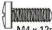 | 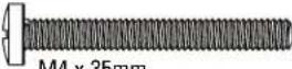 | |
| WTA 16mm | WTA 99mm | ||
| M6 | 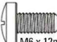 | 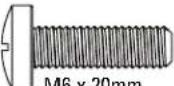 | 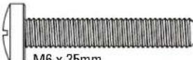 |
| — M6 x 12mm | — M6 x 20mm | — M6 x 30mm | |
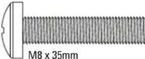
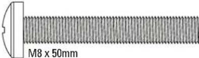
| M8 | 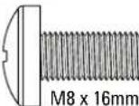 | 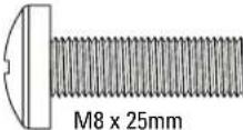 | |
 | |||
 | |||
Parts and Hardware for STEP 2
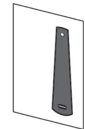
natural_image
Simple 3D illustration of a black rectangular object with a hole and a curved base, isolated on white background (no text or symbols)Drilling Template
07(qty.1)
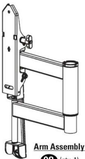
natural_image
Technical line drawing of a mechanical arm assembly (no text or symbols on the diagram itself)08 (qty. 1)
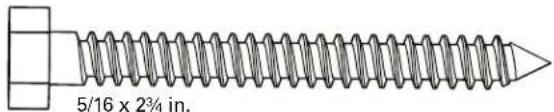
Lag Screw
09 (qty. 2)
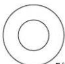
Washer 10 (qty. 2)
5/16 in.
STEP 2B: Concrete Installation Kit CMK1 [NOT INCLUDED]
Contact Customer Service at 1-855-734-7805 to inquire about the CMK1 Concrete Anchor Kit.
Concrete Anchor
C1 (qty. 2)
![SANUS LMF219 - STEP 2B: Concrete Installation Kit CMK1 [NOT INCLUDED] - 1](/content/2026/05/1044048/images/e7e3ad4776042eb3bc0093fbb256401f85bc476650d4fd11e0a04b8d68f03d36.jpg)
Fischer 10X x 60R
Hardware for STEP 3
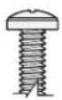
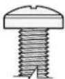
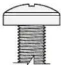
Locking Screw
11
(qty. 1)

M5 x 6mm
Additional Hardware
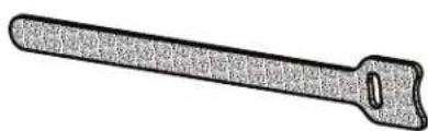
Cable Tie
12 (qty. 2)
natural_image
Simple line drawing of a tool with a handle and jaw (no text or symbols)STEP 1 Attach TV Bracket to TV
1.1 Select TV Screw Diameter
Only one screw size fits your TV.
M4
O
M6
O
M8
O

NOTE: If your TV
ided inset spacers
dapters, use them
PER the mount
ware.
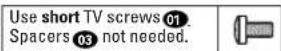
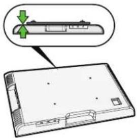
1.2 Select TV Screw Length and Spacers
A
NO SPACER
- Flat Back TV
[TV brackets lay flat on your TV]
natural_image
Diagram of a device with a green arrow pointing to a component, no text or symbols presentB
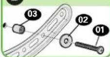
SPACER NEEDED
- Flat Back TV with extra space needed [for deep inset holes or cable interference]
• Rounded or Irregular Back TV [TV brackets NOT resting flat on your TV]
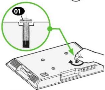
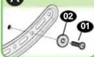
Use long TV screws 01 and spacers 03 to create extra space between the TV and TV bracket.


CAUTION: Verify adequate thread engagement with your screw 01, washer 02, spacer 03 combination AND TV bracket 04.
— Too short will not hold your TV. — Too long will damage your TV.
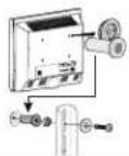
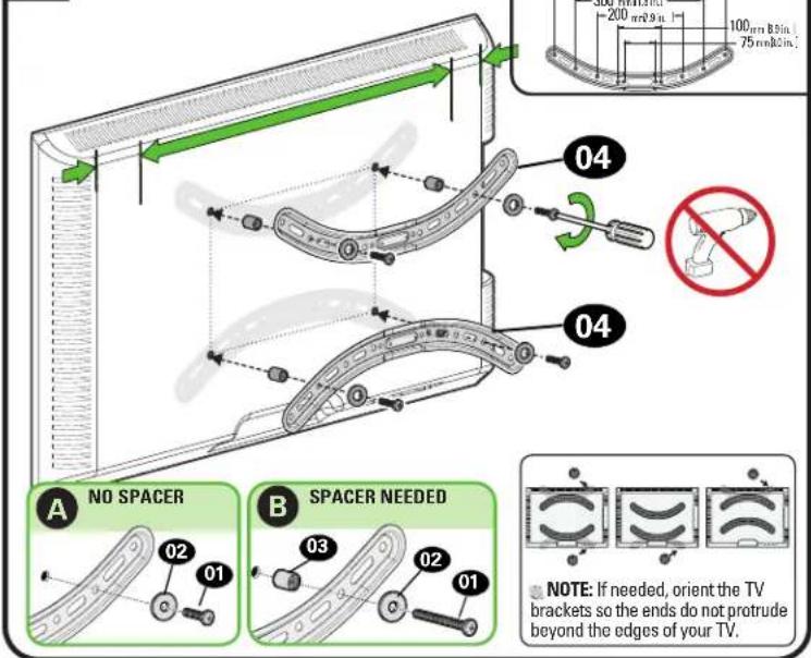
1.3 Attach TV Brackets to Your TV
1 TYPICAL INSTALLATION ILLUSTRATED.
Standard TV (VESA) Hole Patterns
NOTE: If needed, orient the TV brackets so the ends do not protrude beyond the edges of your TV.
2
Center Horizontal TV brackets 04 over your TV's hole pattern and attach using screw combination A or B you selected for your TV.

NOTE: The round holes in TV brackets 04 line up with standard TV (VESA) hole patterns.
CAUTION: Avoid potential personal injuries and property damage! DO NOT use power tools for this step. Tighten the screws 01 only enough to secure the TV brackets to the TV.
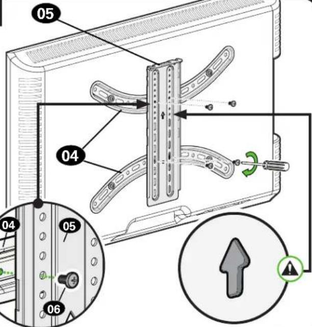
STEP 2A Attach Wall Plate
Wood Stud Installation
CAUTION: Avoid potential personal injury or property damage!
• Drywall covering the wall must not exceed 5/8 in. (16 mm)
• Minimum wood stud size: nominal 2 x 4 in. (51 x 102 mm) actual 1½ x 3½ in. (38 x 89 mm)
• Stud center must be verified
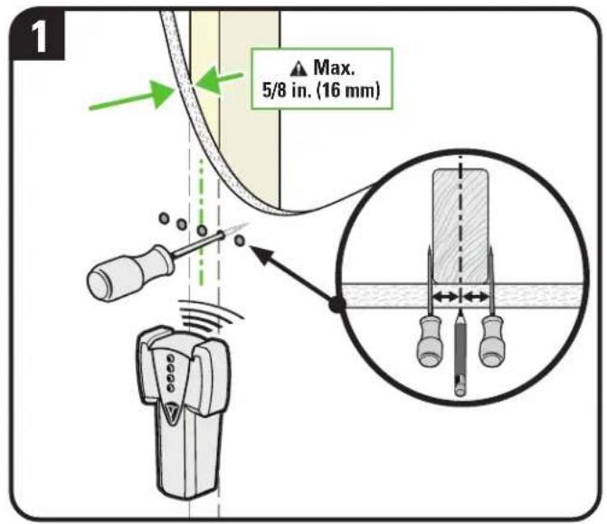
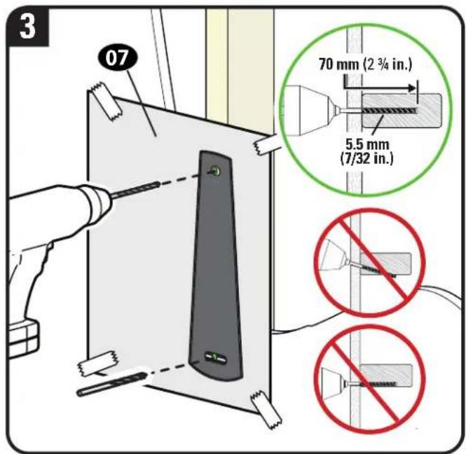
IMPORTANT: Drill into the center of the stud.
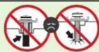
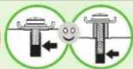
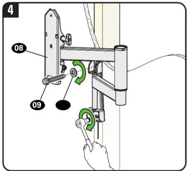
Tighten the lag screws 09 only until the washers 10 are pulled snug against the wall plate 08.
CAUTION: Improper use could reduce the holding power of the lag screw. DO NOT over-tighten the lag screws.
STEP 2B Attach Wall Plate
Solid Concrete or Concrete Block Installation
CAUTION: Avoid potential personal injury or property damage!
- Mount arm assembl 08 directly onto concrete surface (no wall covering)
● Minimum solid concrete thickness: 8 in. (203 mm)
● Minimum concrete block size: 8 x 8 x 16 in. (203 x 203 x 406 mm)
Concrete Installation Kit CMK1 is not included
Contact Customer Service at 1-855-734-7805 to inquire about the CMK1 Concrete Anchor Kit.
CAUTION: Never drill into the mortar between blocks.
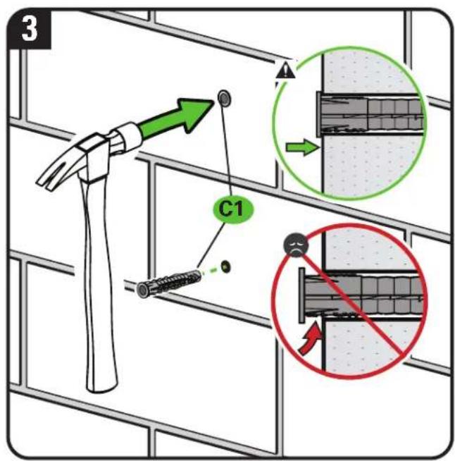
CAUTION: Be sure the anchors C1 are seated flush with the concrete surface.
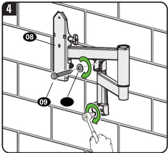
Tighten the lag screws 09 only until the washers 10 are pulled snug against the wall plate 08.
CAUTION: Improper use could reduce the holding power of the lag screw. DO NOT over-tighten the lag screws.
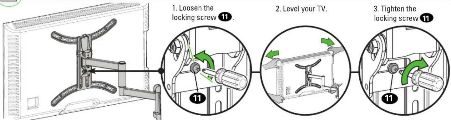
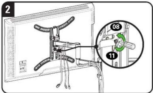
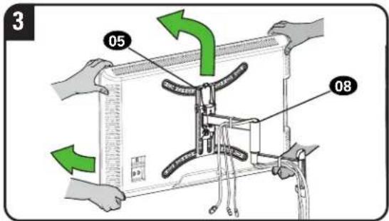
STEP 3 Attach TV to Arm Assembly
3.1 Attach TV to Arm Assembly

HEAVY! You may need assistance with this step.
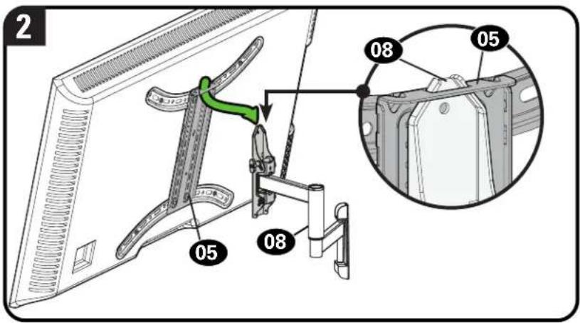
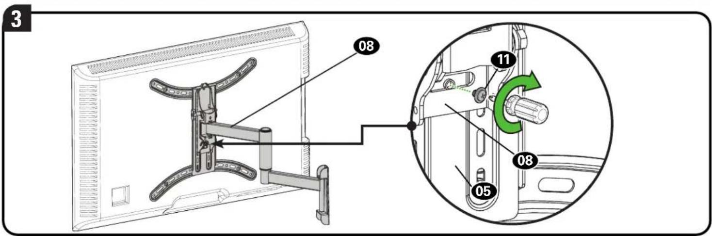
Secure the TV to the arm assembly with the locking screw 11.
To adjust the leveling of your TV, loosen the locking screw 11, level your TV, then tighten the locking screw 11
CAUTION: Avoid potential personal injury or property damage! Locking screw 11 must be installed to secure the TV to the arm assembly 08.
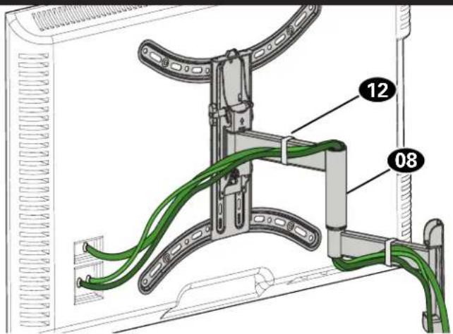
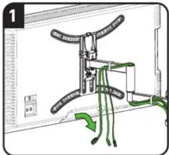
Manage Cables
Fully extend the arms before routing cables.
Use cable ties 12 to bundle and attach cables to the arms 08 for a cleaner look.
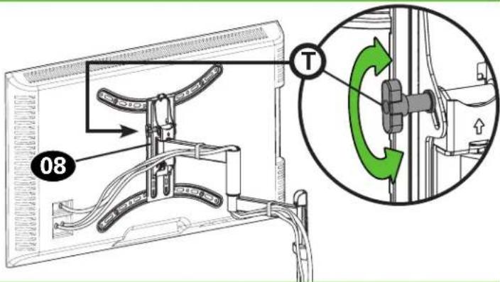
TV Adjustments

TILT ADJUSTMENT
Your TV should adjust easily when moved, then stay in place. If your TV is too loose or too tight, adjust the side tension knob
① by hand.
NOTE: Once your TV is in place, tighten the side tension knob Ⓣ to prevent unwanted movement.
NOTE: Additional tension can be applied using a 3/16 inch hex key (not supplied).

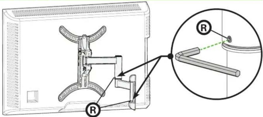
LEVEL ADJUSTMENT

EXTEND / RETRACT -- ONLY IF NECESSARY
Your TV should adjust easily when moved, then stay in place.
If your TV is too loose or too tight when moving, adjust screws Ⓡ using a 3/32 inch hex key (not supplied).
CAUTION: Avoid potential personal injury or property damage!
DO NOT remove screws Ⓗ, only turn enough for slight adjustment.

REMOVING THE TV

HEAVY! You may need assistance with this step.
- Disconnect cables.
- Remove screw

- Lift TV up and off the arm assembly

Thank you for choosing SANUS!
Please take a moment to let us know how we did:

Call us: 1-855-734-7805

Email us: info@sanus.com

Leave a review: SANUS.com
Legrand AV Inc. and its affiliated corporations and subsidiaries (collectively, "Legrand"), intend to make this manual accurate and complete. However, Legrand makes no claim that the information contained herein covers all details, conditions, or variations. Nor does it provide for every possible contingency in connection with the installation or use of this product. The information contained in this document is subject to change without notice or obligation of any kind. Legrand makes no representation of warranty, expressed or implied, regarding the information contained herein. Legrand assumes no responsibility for accuracy, completeness or sufficiency of the information contained in this document.
©2022 Legrand AV Inc. All rights reserved. SANUS is a brand of Legrand. SANUS, HeightFinder, and the SANUS logo are trademarks of Legrand.
