PFPL - TV Stand SANUS - Free user manual and instructions
Find the device manual for free PFPL SANUS in PDF.

User questions about PFPL SANUS
0 question about this device. Answer the ones you know or ask your own.
Ask a new question about this device
Download the instructions for your TV Stand in PDF format for free! Find your manual PFPL - SANUS and take your electronic device back in hand. On this page are published all the documents necessary for the use of your device. PFPL by SANUS.
USER MANUAL PFPL SANUS
Assembly Instructions
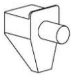
natural_image
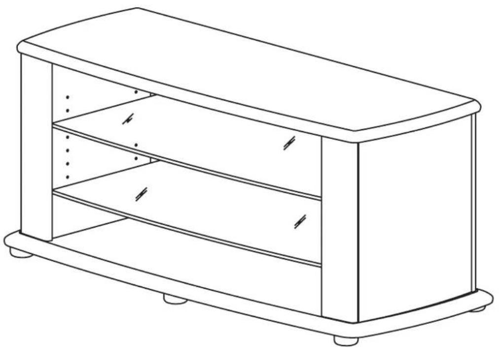
Line drawing of a rectangular box with shelves and legs, no text or symbols presentBUS5305
Congratulations and thank you for purchasing your new Sanus Platinum Furniture Product. If you have any questions regarding this or any other Sanus product, please contact our customer service department at (800)359-5520, or www.sanus.com. It is not necessary to contact the retailer with any questions or problems, as parts can be sent directly to you
Please follow these assembly instructions. This will save you time, make assembly easier and prevent possible damage to your new Digital TV Stand. Assistance may be required for some assembly procedures. Correct assembly is your responsibility.
We recommend that the unit is assembled on a soft surface such as carpet. Please record your serial number in the space provided below and retain this manual for future reference.
Serial No
This unit was manufactured using ISO 9000 certified systems. For improvement purposes, design and specifications are subject to change without notice.

UNPACK AND IDENTIFY PARTS
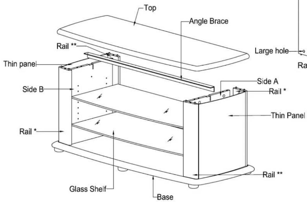
PART DESCRIPTION:
| Top | 1 |
| Base | 1 |
| Side A | 1 |
| Side B | 1 |
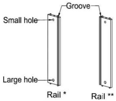
| Rail * | 2 |
| Rail ** | 2 |
| Thin panel | 2 |
| Glass Shelf | 2 |
| Angle Brace | 1 |
| Glide | 6 |
| Hardware Pack | 1 |
PART NUMBER
| Stipple silver |
| M19965A1SS |
| M19966A1SS |
| M19967A1SS |
| M19968A1SS |
| M19969A1SS |
| M19970A1SS |
| M19971A1SS |
| M19972A1PO |
| M19111A1PO |
| P815049 |
| MH1139A0 |
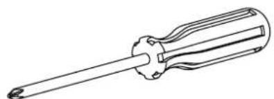
TOOLS REQUIRED:
natural_image
Line drawing of a screwdriver with a cylindrical head and threaded shaft (no text or symbols)PHILLIPS No.2 SCREWDRIVER
CUSTOMER SERVICE INFORMATION
IN THE UNLIKELY EVENT OF PARTS BEING FAULTY OR MISSING, CHECK PACKAGING. REPLACEMENT PARTS CAN BE OBTAINED BY CALLING THE TOLL FREE NUMBER WITHIN 14 DAYS OF PURCHASE.
TOLL-FREE NUMBER - 1800-359-5520 (USA ONLY)
THE FOLLOWING INFORMATION MUST BE SUPPLIED IN FULL:
- YOUR NAME, ADDRESS AND TELEPHONE NUMBER.
- PRODUCT MODEL NAME/NUMBER AND COLOR.
-
DESCRIPTION, PART NUMBER AND QUANTITY OF REQUIRED PARTS.
-
PURCHASE DETAILS: -STORE THE UNIT WAS PURCHASED FROM.
-DATE OF PURCHASE.
- SERIAL NUMBER OF THE UNIT PURCHASED.
(LOCATED ON REAR OF UNIT)
Hardware Contents:
CAUTION
There are many small components used in the construction of this unit.
These loose items should be kept away from young children while
assemblingyourunit.
ShelfPin
P840048x8
P860121x1
P860035x6

Barrelnut
P840050x8
P860015x8
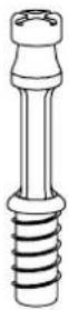
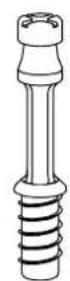
Connectorrod
P820016Tx8
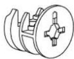
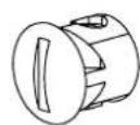
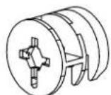
Cam
P820015Tx8
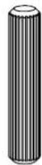
Woodendowel
P800201x8

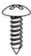
natural_image
Simple line drawing of a cylindrical object with a coiled spring (no text or symbols)P816145x4
natural_image
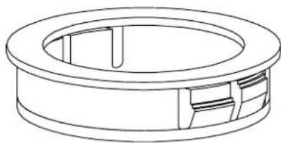
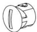
Technical line drawing of a circular mechanical component with internal slots and mounting holes (no text or symbols)CableDucts
P840170x2
STEP 1
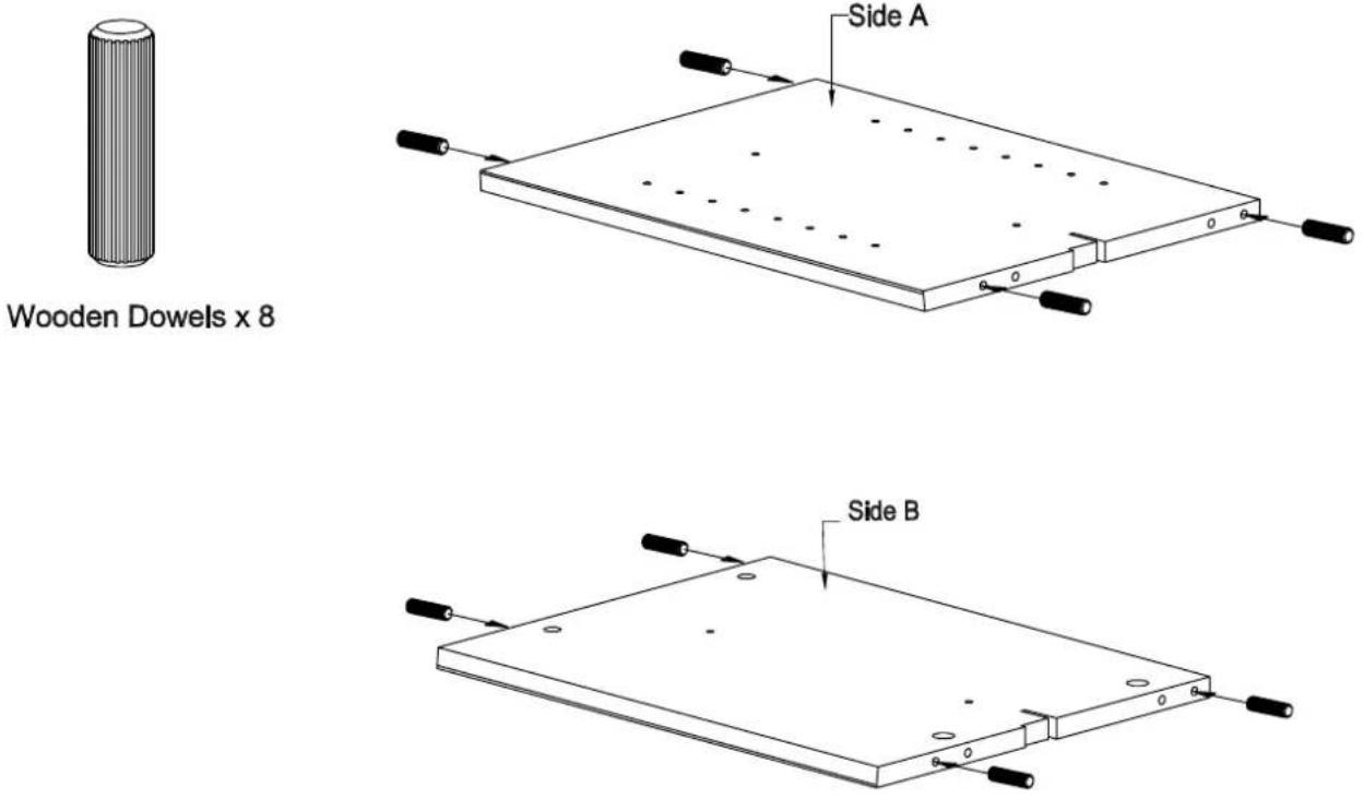
Insertwoodendowelsintosidesasshown.
STEP 2
× 8
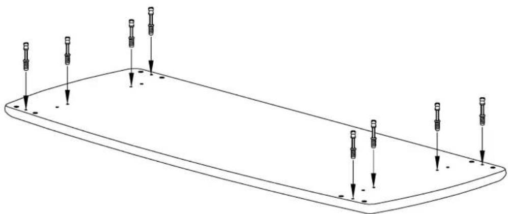
natural_image
Pure technical line drawing of a rectangular plate with eight screw holes and downward arrows indicating depth (no text or symbols)1.Fasten8ConnectorRodsintosmallholesinTopasshown.
STEP 3
Black Barrel nut x 4
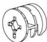
Cam x 4
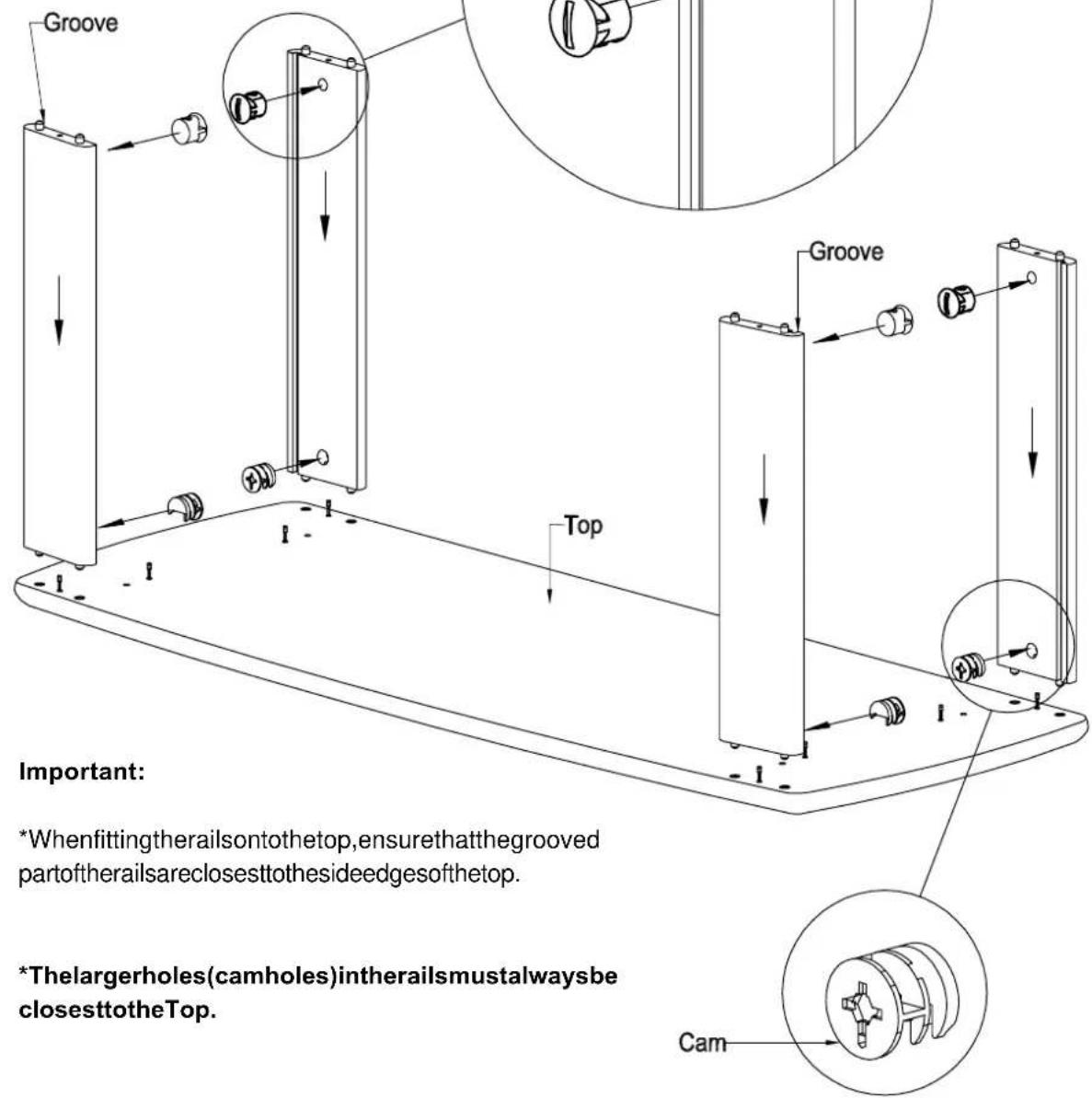
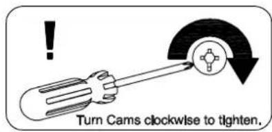
- InsertblackBarrelNutsintosmallerholesinRails,ensuringslotincapisalignedtointersectinghole.
- Insert silver Cams into larger holes in Rails, ensuring that arrow on Cam points towards intersecting hole.
- PressfitRailstoTopasshown.
IMPORTANT
The new Sanus stand has been designed to complement TVs with curved and flat bases. The stand can be assembled with either curved front top & base or flat front top & base facing forward. Most steps in the assembly instructions are the same for both designs. However, steps 4A,5A,6A and 7A are for the curved front stand option whereas steps 4B,5B,6B and 7B are for the flat front stand option.
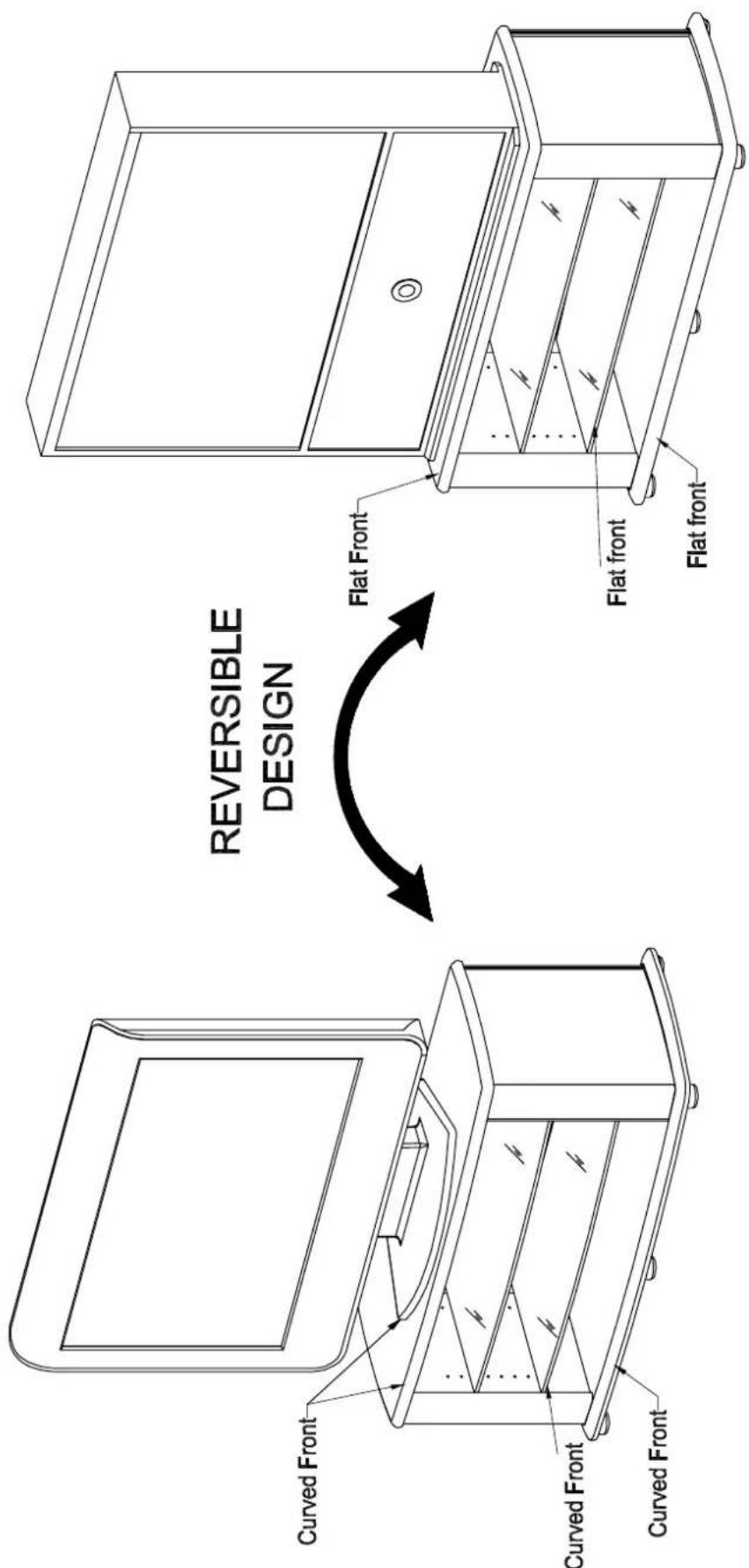
Sanus stand with flat front design complementing TVs with flat base.
Sanus stand with curved front design complementing TVs with curved base.
ASSEMBLING THE STAND WITH CURVED FRONT.
STEP 4 A
Black Barrel nut x 4

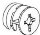
- Insert black Barrel Nuts into holes in Sides, ensuring slot in cap is aligned to intersecting hole.
- Insert silver Cams into large holes in sides, ensuring that arrow on Cam points towards Top panel.
- Press fit Side's to Top, ensuring Angle Brace is in slots in Sides (ensuring orientation of Metal Brace as shown).
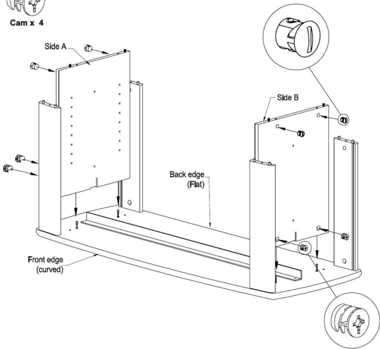
STEP 5 A
- Secure Angle Brace to Top as shown above.
STEP 6 A
natural_image
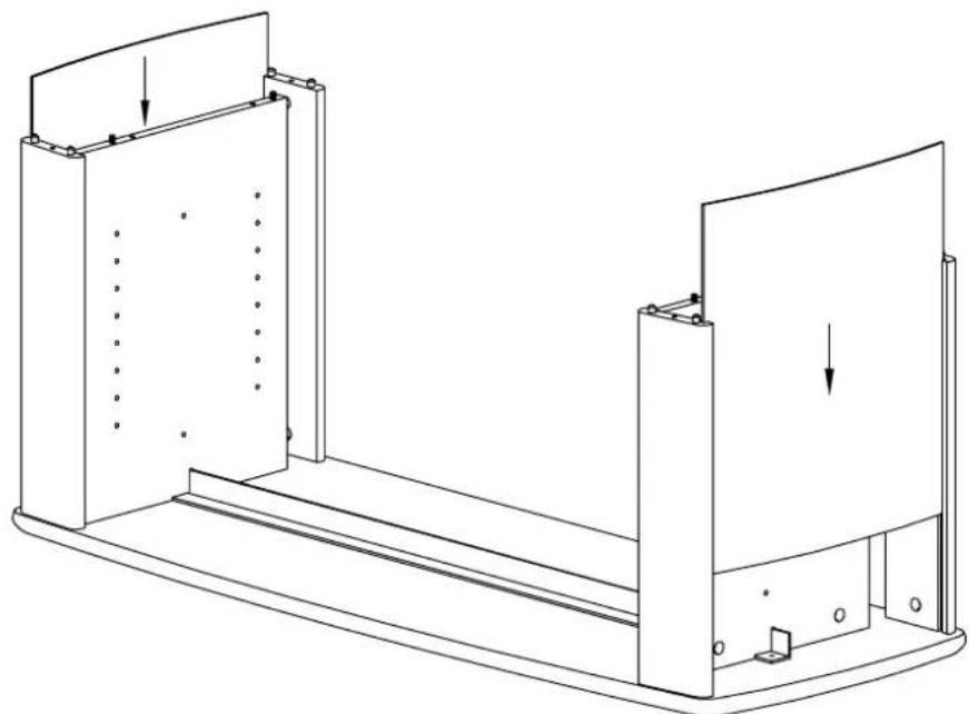
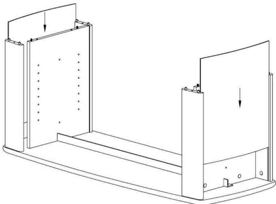
Technical line drawing of a mechanical assembly with two components and directional arrows indicating force or movement (no text or symbols)- Slide Thin Panels down slots in Rails, ensuring Silver surfaces face out.
STEP 7 A
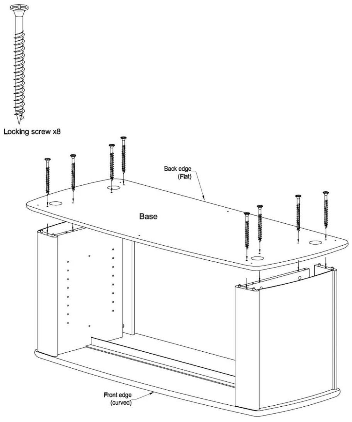
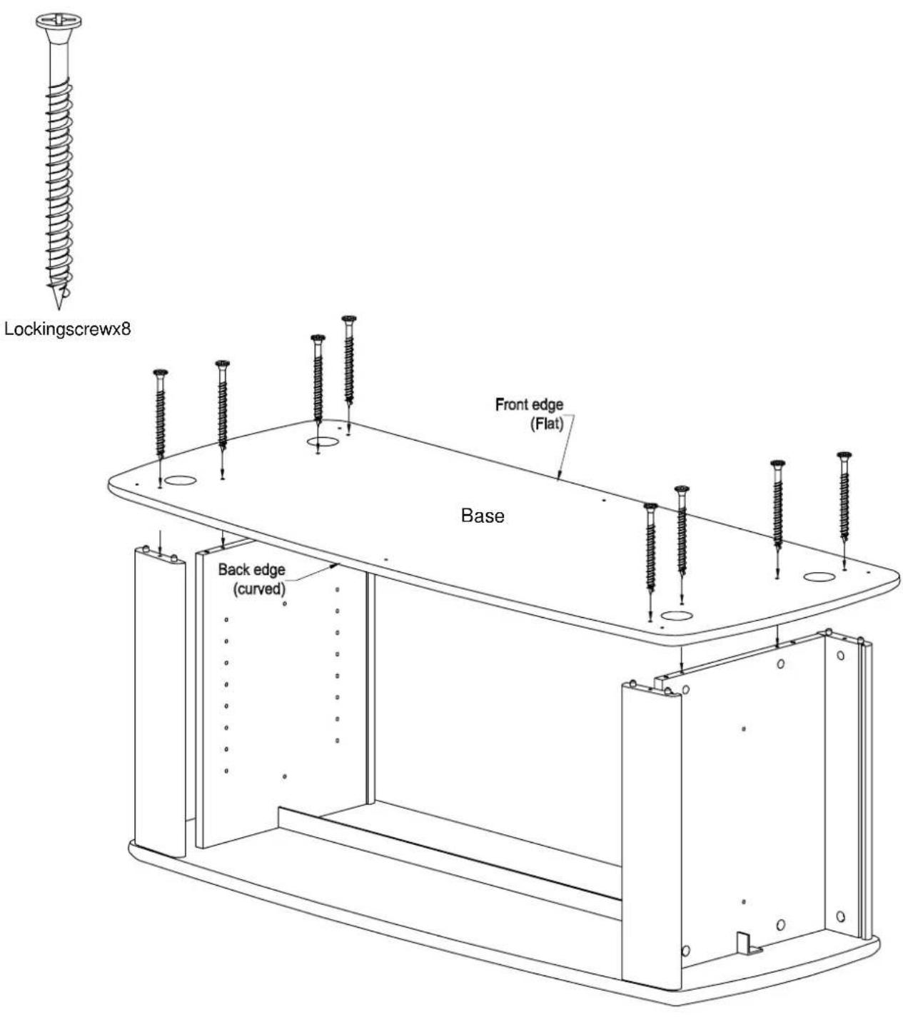
- With assistance align Base onto Dowels In Sides & Rails & then press flt.
- Fasten large Locking screws through Base into Sides & Rails (Screw heads should be flush with surface).
ASSEMBLING THE STAND WITH FLAT FRONT.
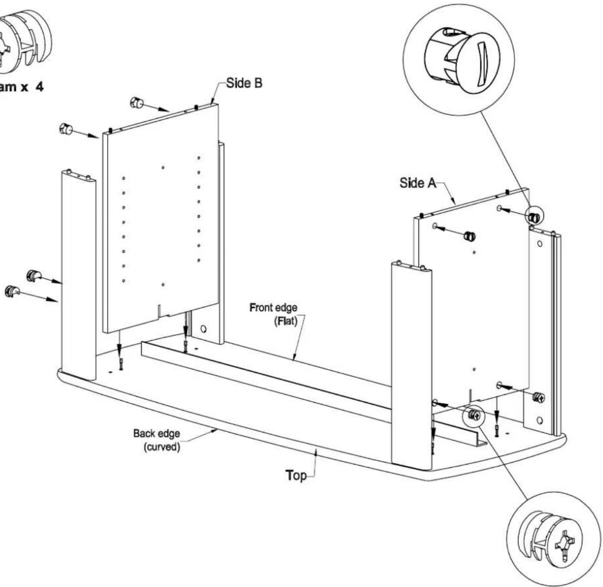
STEP 4 B
Black Barrel nut x 4
Cam x 4
-
Insert black Barrel Nuts into holes in Sides, ensuring slot in cap is aligned to intersecting hole.
-
Insert silver Cams into large holes in sides, ensuring that arrow on Cam points towards Top panel.
-
Press fit Side's to Top, ensuring Angle Brace is in slots in Sides (ensuring orientation of Metal Brace as shown).
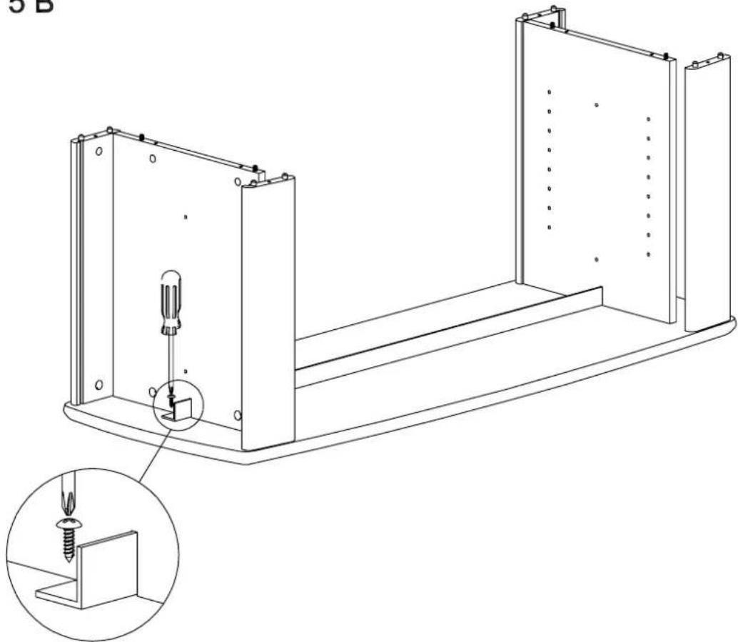
STEP 5 B
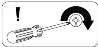
natural_image
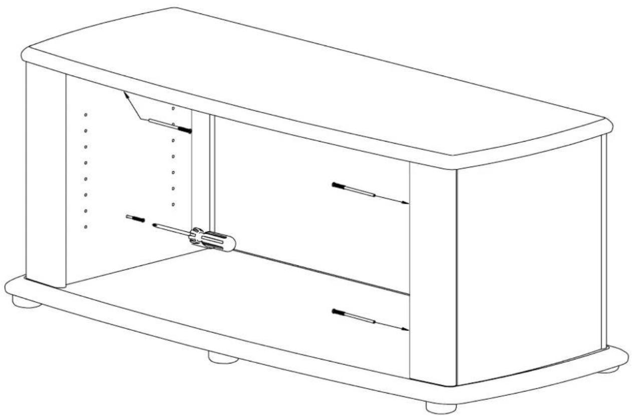
Technical line drawing of a mechanical assembly with a screwdriver inserted into a housing, showing internal components and a magnified inset (no text or symbols)- Secure Angle brace to Top as shown above.
STEP 6 B
natural_image
Technical line drawing of a mechanical assembly with two rectangular components and mounting holes (no text or symbols)- Slide Thin Panels down slots in Rails, ensuring Silver surfaces face out.
STEP 7 B
-
With assistance align Base onto Dowels in Sides & Rails & then press fit.
-
Fasten large Locking screws through Base into Sides & Rails (Screw heads should be flush with surface).
Following steps apply to both flat and curved front designs.
STEP 8
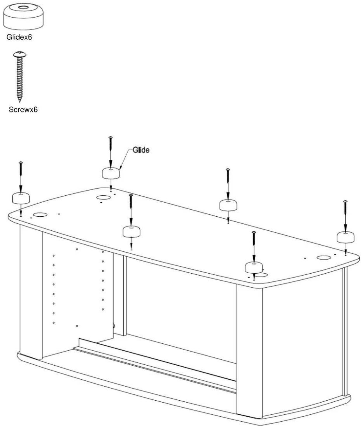
- Fastentheglidestothebaseasshown.
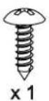
STEP 9
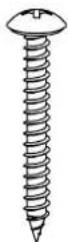
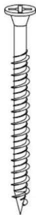
natural_image
Simple line drawing of a cylindrical object with a coiled spring (no text or symbols)Adjustingscrewx4
natural_image
Line drawing of a rectangular electronic device with internal components and mounting feet (no text or symbols)- Turnunitovercarefully.
- Screw each Adjusting screw into Side by half of it's visible threaded length, then once this isdone,tightenall4AdjustingscrewsfullyintoSide.
STEP 10
ShelfPinx8
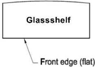
Curvededgeoftheglass shelvesmustbeplacedatfront for curvedfrontdesign.
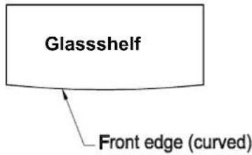
Flatedgeoftheglass shelvesmustbeplacedat frontforthe flatfrontdesign.
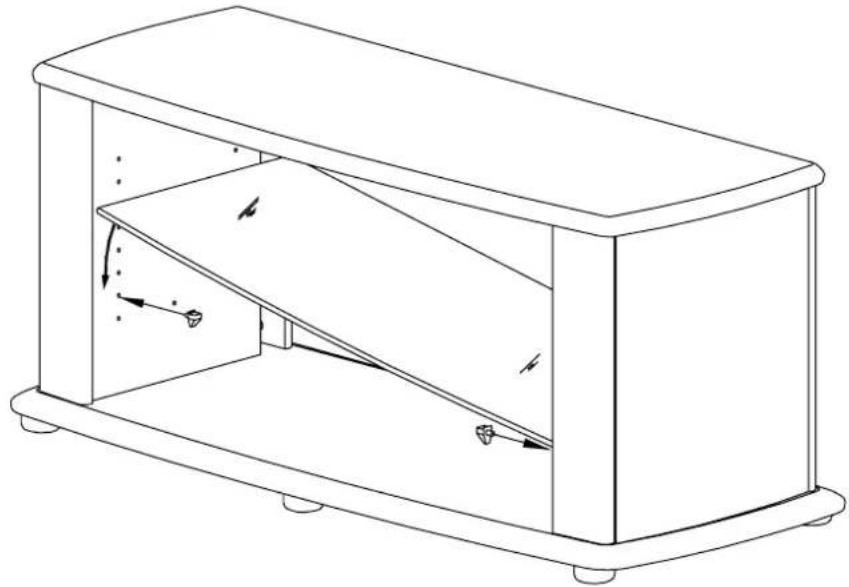
natural_image
Line drawing of a rectangular box with internal diagonal structure and directional arrows indicating motion (no text or symbols)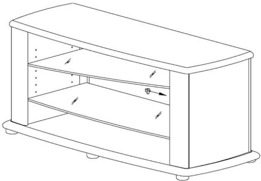
natural_image
Line drawing of a rectangular box with internal shelves and mounting feet (no text or symbols)- Insert Shelf Pins into holes at the lower position of both the Sides (as illustrated above).
- Tilt and slide Glass Shelf between Rails (ensuring frosted side down) and place on top of Shelf Pins.
3.InsertShelfPinsintoholesattheupperpositionsofoneSideonly. - Tilt and slide the second Glass Shelf between Side Rails. While holding one end of the shelf on pins on one side insert remaining Shelf Pins into other side beneath Glass, then lower the shelf on top of the pins.
STEP 11
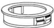
Cable Duct x2
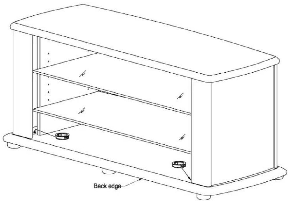
natural_image
Technical line drawing of a rectangular electronic device with labeled back edge (no text or symbols beyond label)- Pressfit2CableDuctsintolargeholesintheBase.
- You havenow completed the assembly of your new Digital TV stand.
NOTE: Were recommend that all contents stored in or on this item off furniture be removed before shifting it. The manufacturers will not be held liable for damage caused when furniture is shifted without first removing its contents. If furniture is shifted were recommend that it is lifted not dragged.
