22846 - Model making Trix - Free user manual and instructions
Find the device manual for free 22846 Trix in PDF.


| Product type | Electric locomotive model |
| Brand | Trix |
| Model | 22846 |
| Supported digital protocols | mfx, DCC, MM (multiprotocol) |
| Factory DCC / MM address | DCC 03, MM 44 |
| Analog power supply | 15 V DC maximum |
| Digital power supply | 22 V AC maximum |
| Minimum curve radius | 360 mm |
| Number of speed steps | 14, 28 or 126 (configurable) |
| Sound functions | Whistle, brake squeal, fan, compressor, station announcement, sanding, etc. |
| Lighting | Reversed directional lighting according to direction of travel, switchable lights in digital mode, cab lighting, long-range headlights |
| Acceleration/braking delay | Configurable via CV 3 and CV 4 |
| Function mapping | Programmable (assignment of functions to keys) |
| Deactivation of protocols | Possible via CV 50 |
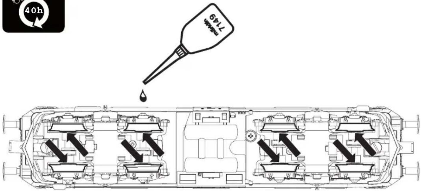
| Maintenance | Cleaning wheels and contacts, periodic lubrication, avoid humidity |
| Safety | Do not expose to humidity, strong temperature variations, direct sunlight. Beware of sharp edges. LED laser class 1. |
| Repairs and spare parts | Contact a specialized Trix dealer or Märklin customer service |
| Warranty | Statutory and contractual warranty (see certificate provided) |
| Recommended accessories | Interference suppression set ref. E611 655 for analog operation |
| Number of manual pages | 64 pages |
Frequently Asked Questions - 22846 Trix
User questions about 22846 Trix
0 question about this device. Answer the ones you know or ask your own.
Ask a new question about this device
Download the instructions for your Model making in PDF format for free! Find your manual 22846 - Trix and take your electronic device back in hand. On this page are published all the documents necessary for the use of your device. 22846 by Trix.
USER MANUAL 22846 Trix
natural_image
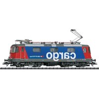
Side profile of a blue and red SBB CFF FFS Cargo electric locomotive (no visible text or symbols on the vehicle body)D GB USA F NL
Table of Contents Page
Safety Notes 9
Important Notes 9
Controllable Functions 12
Parameter/Register 13
Complementary accessories 24
Service and maintenance 25
Spare Parts 30
- This locomotive is only to be used with the operating system it is designed for.
- Analog max. 15 volts DC, digital max. 22 volts AC.
- This locomotive must never be supplied with power from more than one power pack.
- Please make note of the safety notes in the instructions for your operating system.
- The feeder track must be equipped to prevent interference with radio and television reception, when the locomotive is to be run in conventional operation. The E611 655 interference suppression set is to be used for this purpose. The interference suppression set is not suitable for digital operation.
- WARNING! Sharp edges and points required for operation.
- Do not expose the model to direct sunlight, extreme changes in temperature, or high humidity.
- The LEDs in this item correspond to Laser Class 1 according to Standard EN 60825-1.
Important Notes
- The operating instructions and the packaging are a component part of the product and must therefore be kept as well as transferred along with the product to others.
- Please see your authorized Trix dealer for repairs or spare parts.
- The warranty card included with this product specifies the warranty conditions.
-
Disposing: www.maerklin.com/en/imprint.html
-
The full range of functions is only available under DCC and mfx.
- Built-in headlights that change over with the direction of travel. They can be turned on and off in digital operation.
• Minimum radius for operation is 360 mm/14-3/16". - The locomotive cannot be switched to operation from catenary.
This decoder can also be operated on analog layouts or areas of track that are analog. The decoder recognizes alternating current (DC) and automatically adapts to the analog track voltage. All functions that were set under mfx or DCC for analog operation are active (see Digital Operation).
Digital Operation
The decoders are multi-protocol decoders. These decoders can be used under the following digital protocols: mfx, DCC or MM.
Address set at the factory: DCC 03 / MM 44
The digital protocol with the most possibilities is the highest order digital protocol. The sequence of digital protocols in descending order is:
Priority 1: mfx
Priority 2: DCC
Priority 3: MM
Note: If two or more digital protocols are recognized in the track, the decoder automatically takes on the highest value digital protocol. For example, if mfx & DCC are recognized, the mfx digital protocol is taken on by the decoder. Individual protocols can be deactivated with Parameter CV 50.
Note: Please note that not all functions are possible in all digital protocols. Several settings for functions, which are supposed to be active in analog operation, can be done under mfx and DCC.
Notes on digital operation
- The operating instructions for your central unit will give you exact procedures for setting the different parameters.
- The setting done at the factory does not permit operation with opposite polarity DC power in the braking block. If you want this characteristic, you must do without conventional DC power operation (CV 29/Bit 2 = 0).
mfx Protocol
Addresses
- No address is required; each decoder is given a one-time, unique identifier (UID).
- The decoder automatically registers itself on a Central Station or a Mobile Station with its UID.
• Name set at the factory: 421 378-1 SBBC
Programming
- The characteristics can be programmed using the graphic screen on the Central Station or also partially with the Mobile Station.
- All of the Configuration Variables (CV) can be read and programmed repeatedly.
- The programming can be done either on the main track or the programming track.
- The default settings (factory settings) can be produced repeatedly.
- Function mapping: Functions can be assigned to any of the function buttons with the help of the 60212 Central Station (with limitations) and with the 60213/60214/60215/60216/60226 Central Station (See help section in the Central Station).
DCC Protocol
Addresses
• Possible addresses: short, long, and m.u. address
- Address range:
1 - 127 (short address, m.u. address)
1 - 10239 (long address)
- Every address can be programmed manually.
- A short or a long address is selected using the CVs.
- A multiple unit address that is being used deactivates the standard address.
Programming
- The characteristics can be changed repeatedly using the Configuration Variables (CV).
- The CV numbers and the CV values are entered directly.
- The CVs can be read and programmed repeatedly. (Programming is done on the programming track.)
- The CVs can be programmed, as you desire. PoM (Programming on the layout track) is only possible with those CVs marked in the CV table. PoM must be supported by your central controller (see the instructions for your controller).
- The default settings (factory settings) can be produced repeatedly.
• 14 or 28/126 speed levels can be set. - All of the functions can be controlled according to the function mapping (see CV description).
- See the CV description for the DCC protocol for additional information.
We recommend that in general programming should be done on the programming track.
Logic Functions
Acceleration / Braking Delay
- The acceleration and braking times can be set separately from each other.
- The logical function shut off for ABV (Acceleration / Braking Delay) can be assigned to any function button by means of function mapping.
| Controllable Functions | DC/AC | MS I1 | MS II2 | CS I | CS II/III | |
| Headlights with „Swiss headlight changeover“ | F0 | |||||
| Switching marker lights (1 x white -> 1 x red)3 | F1 | |||||
| Sound effect: Operating sounds5 | F2 | |||||
| Sound effect: Locomotive whistle F3 | ||||||
| Sound effect: Squealing brakes off F4 | ||||||
| Engine room lighting F5 | ||||||
| Engineer's cab 1 lighting F6 | ||||||
| Long distance headlights F7 | ||||||
| Engineer's cab 2 lighting F8 | ||||||
| ABV off F9 | ||||||
| Headlights Engineer's Cab 2 off3,4 | F10 | |||||
| Headlights Engineer's Cab 1 off3,4 | F11 | |||||
| Sound effect: Blower F12 | ||||||
| Sound effect: Letting off air F13 | ||||||
| Pantograph sound (up/down) F14 |
| Controllable Functions | DC/AC | MS I1 | MS II2 | CS I | CS II/III | |
| Sound effect: Sanding F16 | ||||||
| Sound effect: Open/Close cab doors F17 | ||||||
| Sound effect: Compressor F18 | ||||||
| Sound effect: Station announcements F19 | ||||||
| Sound effect: Coupling / uncoupling F20 | ||||||
| Sound effect: Conductor whistle F21 | ||||||
| Sound effect: Main relay F22 | ||||||
| Sound effect: Switching whistle | F23 | |||||
| Low speed switching range | F24 |
^1 Trix Systems
^2 Functions starting at F16 are not possible until you have Software Version 3.55 in the MS2.
^3 Only in conjunction with the headlights
^4 Switched together: Warning light(s) in Switzerland
^5 with random sounds
| CV | Discription | DCC Value Factory-Set | |||
| 1 | Address | 1 - 127 | 3 | ||
| 2 | PoM Minimum Speed 0 - 255 | 4 | |||
| 3 | PoM Acceleration delay 0 - 255 | 22 | |||
| 4 | PoM Braking delay 0 - 255 | 22 | |||
| 5 | PoM Maximum speed 0 - 255 | 190 | |||
| 8 | Factory | Reset / Manufacturer Recognition 8 | 131 | ||
| 13 | PoM Functions F1 - F8 in analog operation 0 - 255 | 0 | |||
| 14 | PoM Functions F9 - F15 and lights in analog operation 0 - 255 | 1 | |||
| 17 | Extended address (upper part) | CV 29, Bit 5 =1 | 192 | ||
| 18 | Extended address (lower part) | CV 29, Bit 5 =1 | 128 | ||
| 19 | Multiple Unit Address | 0 - 255 | 0 | ||
| 21 | PoM Functions F1 - F8 on Multiple Unit | 0 - 255 | 0 | ||
| 22 | PoM Functions F9 - F15 and lights on Multiple Unit | 0 - 255 | 0 | ||
| 29 | PoM | Bit 0: Reversing direction of travel | 0 / 1 | 0 - 7 | 6 |
| Bit 1: Number of speed levels 14 or 28/128* | 0 / 2 | ||||
| Bit 2: DCC operation with a braking area (no analog operation possible) | 0 / 4 | 32 - 39 | |||
| Bit 5: short / long address | 0 / 32 | ||||
| 50 | PoM | Alternative Protocols (DCC cannot deactivate itself) | 0 / 1 | 0 - 15 | 15 |
| Bit 0: Analog AC off = 0 / Analog AC on = 1 | 0 / 1 | ||||
| Bit 1: Analog DC off = 0 / Analog DC on = 1 | 0 / 2 | ||||
| Bit 2: fx (MM) off = 0 / fx (MM) on = 1 | 0 / 4 | ||||
| Bit 3: mfx off = 0 / mfx on = 1 | 0 / 8 | ||||
| 63 | PoM Volume | 0 - 255 | 255 | ||
* The speed levels on the locomotive decoder and on the controller must agree with each other; otherwise, you may have malfunctions.
natural_image
Icon of a vintage train with motion arrows and signal waves (no text or symbols)
natural_image
Side profile line drawing of a vintage tram car with side-mounted engine and exhaust pipe (no text or symbols)
natural_image
Side profile line drawing of a train car with visible engine and side panel (no text or symbols)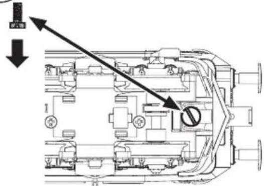
text_image
Technical diagram of a mechanical assembly with labeled components and directional arrows indicating flow or movement.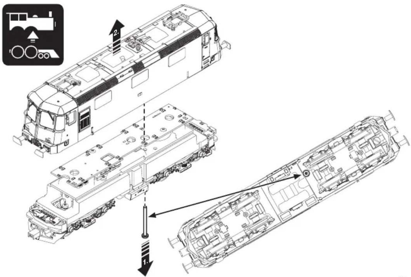
text_image
Technical diagram of a train assembly with labeled components and directional arrows indicating assembly steps.
natural_image
Two directional arrows, one left-pointing and one right-pointing, on a dark background (no text or symbols)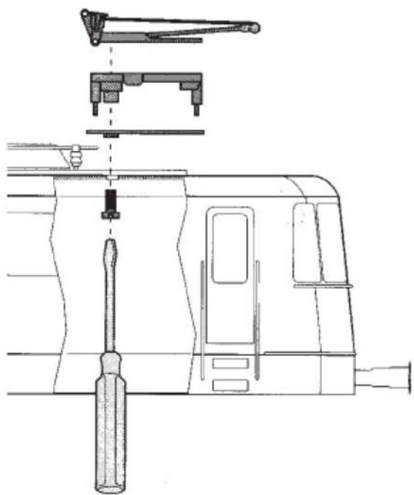
natural_image
Technical line drawing of a mechanical assembly with tool and component details (no text or symbols)
natural_image
Symbol of a right-hand rule with a key and handle, no text or numbers present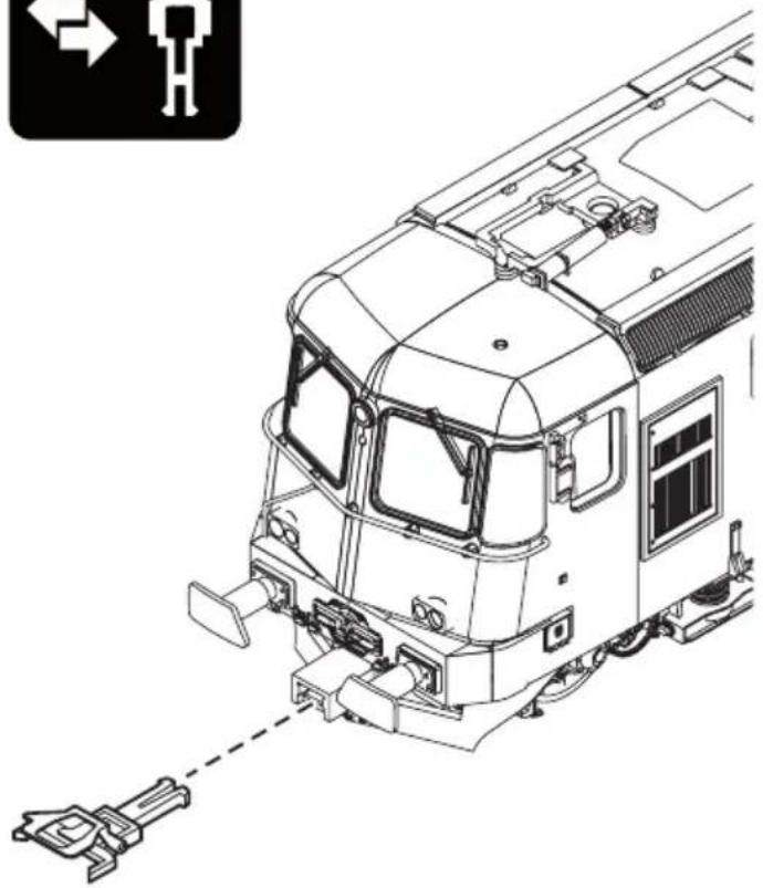
natural_image
Technical line drawing of a train front view with visible tracks and structural components (no text or symbols)
natural_image
Diagram showing a car wheel with a circular arrow indicating rotation (no text or symbols)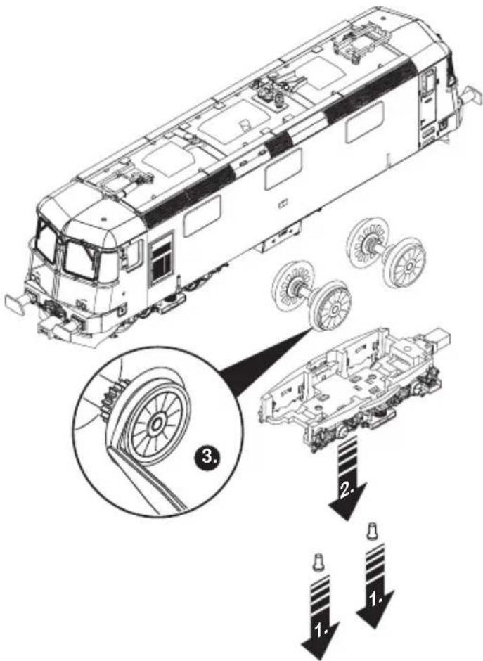
text_image
Technical diagram of a train car with labeled components and assembly steps, including wheel assembly and component disassembly.
natural_image
Icon depicting a train with a fuel pump and a 40-hour cycle arrow, no text or symbols present.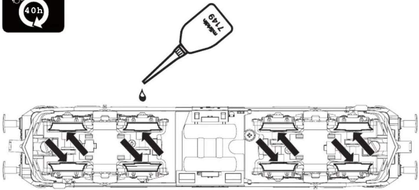
Note: Several parts are offered unpainted or in another color. Parts that are not listed here can only be repaired by the Märklin repair service department.
General Note to Avoid Electromagnetic Interference:
A permanent, flawless wheel-rail contact is required in order to guarantee operation for which a model is designed. Do not make any changes to current-conducting parts.
natural_image
Side profile of a red and blue SBB CFF FFS Cargo electric locomotive on railway tracks (no visible text or symbols beyond branding)E I S DK
Reservedele => D GB USA F NL 30
Aviso de seguridad
natural_image
Icon of a vintage train with motion arrows and signal waves (no text or symbols)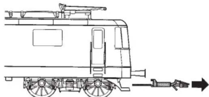
natural_image
Side profile line drawing of a vintage tram car with side-mounted engine and exhaust pipe (no text or symbols)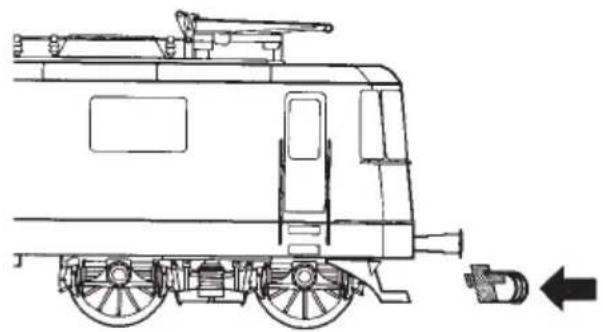
natural_image
Side profile line drawing of a train car with visible engine and side panel (no text or symbols)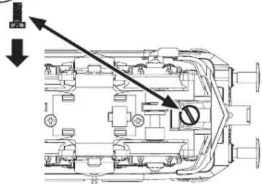
text_image
Technical diagram of a mechanical assembly with labeled components and directional arrows indicating flow or movement.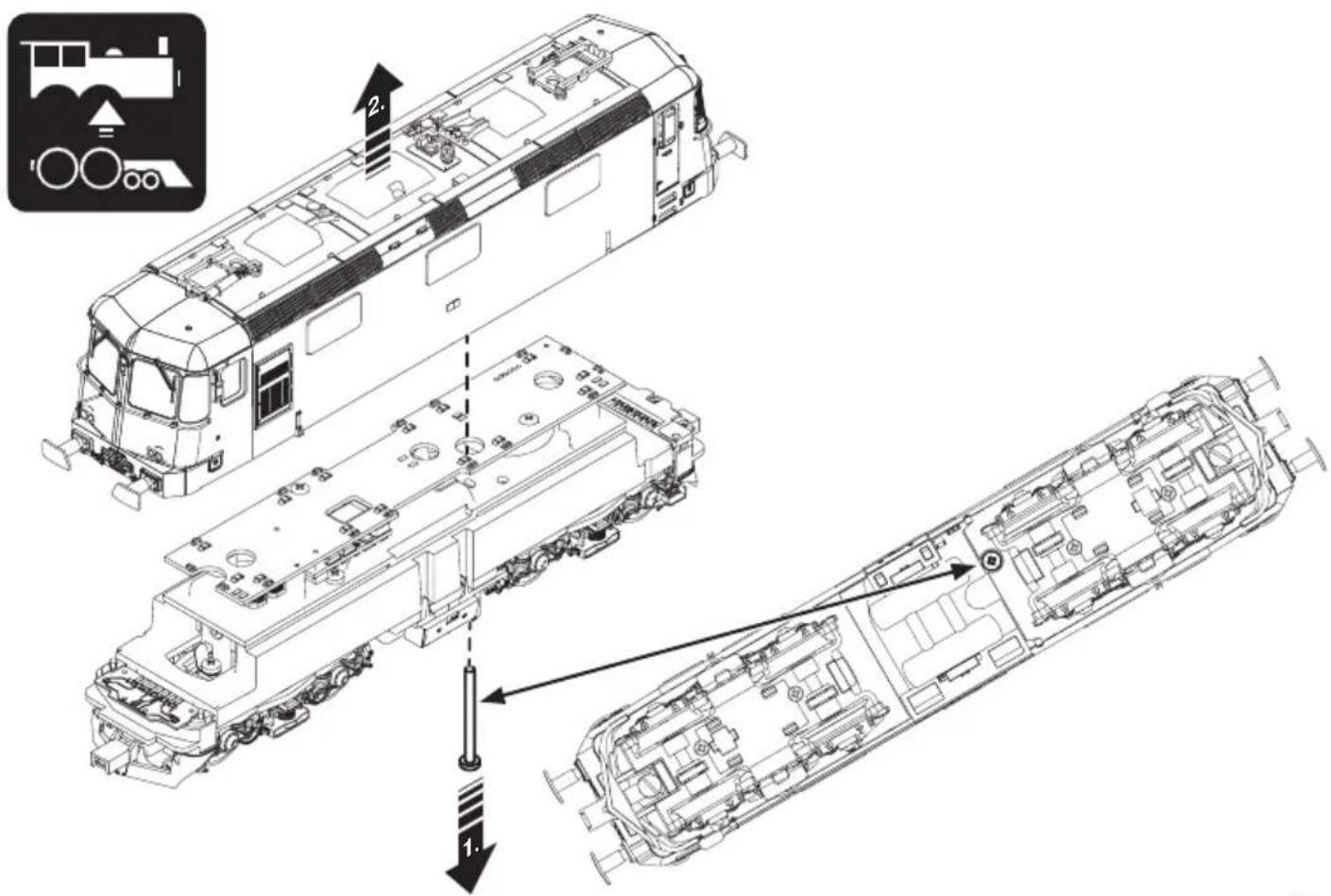
text_image
Technical diagram of a train assembly with labeled components and directional arrows indicating assembly steps.
natural_image
Two directional arrows, one left-pointing and one right-pointing, on a dark background (no text or symbols)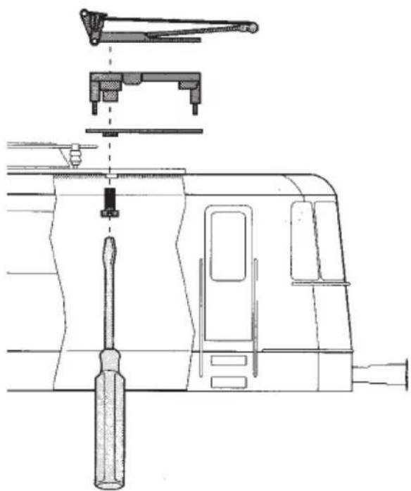
natural_image
Technical line drawing of a mechanical assembly with tool and component details (no text or symbols)
natural_image
Symbol of a right-hand rule with a key and handle, no text or numbers present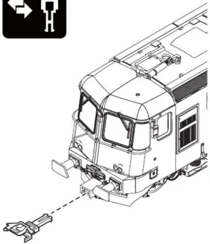
natural_image
Technical line drawing of a train front view with visible tracks and structural components (no text or symbols)
natural_image
Diagram showing a car wheel with a circular arrow indicating rotation (no text or symbols)
text_image
Technical diagram of a train car with labeled components and assembly steps, including wheel assembly and component disassembly.
natural_image
Icon depicting a train with a fuel pump and a 40-hour cycle arrow, no text or symbols present.