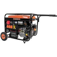
CPG 5500 NEV - Generator CrossTools - Free user manual and instructions
Find the device manual for free CPG 5500 NEV CrossTools in PDF.


User questions about CPG 5500 NEV CrossTools
0 question about this device. Answer the ones you know or ask your own.
Ask a new question about this device
Download the instructions for your Generator in PDF format for free! Find your manual CPG 5500 NEV - CrossTools and take your electronic device back in hand. On this page are published all the documents necessary for the use of your device. CPG 5500 NEV by CrossTools.
USER MANUAL CPG 5500 NEV CrossTools
Operating Instructions - Electric generator
F
Conformity assessment was made according annex VI of directive 2000/14/EC
Service Email: service@tip-pumpen.de
Reparatur Service
Tel.: 07263/91250
Congratulations for buying your new device from Cross Tools!
Like all our products, this one, too, was developed using the latest technological knowledge. The device was manufactured and assembled on the basis of state-of-the-art pump technology using most reliable electrical or electronic components which ensure a high level of quality and a long life of your new product. Please read through these operating instructions carefully to make sure that you can fully benefit from all features. Some explanatory illustrations can be found at the end of these operating instructions.
We hope you will enjoy your new device!
Please read through these operating instructions carefully and make yourself conversant with the control elements and the proper use of this product. We shall not be liable in the case of damage caused as a result of the nonobservance of instructions and provisions of the present operating instructions. Any damage caused as a result of the nonobservance of the instructions and regulations contained in the present operating instructions shall not be covered by the warranty terms. Please keep these operating instructions in a safe place and hand them on together with the device should you ever dispose of it.
List of Contents
- Device description 1
- Technical Data 2
- Scope of delivery 3
- Safety information 3
- Assembly instructions 7
- Putting into operation 8
- Maintenance and cleaning 12
- Transport and storage 14
- Troubleshooting 15
- Warranty 16
- How to order spare parts 16
- Service 17
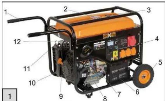
1. Device description
- L-handle
- Tank cap
- Fuel gauge
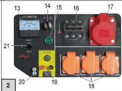
- Control panel
- Complete wheels
- Battery
- Oil dipstick / Oil filler screw
- Oil drain screw
- Pull-cord starter
- Air filter housing
- Choke lever
- Fuel cock
- Voltmeter
- Ignition key switch
- Operating indicator
- safety switch
- Socket 230 V (Schuko)
- AC Connections (230V)
- DC connection (12 VDC)
- Earth connection
- Main / changeover switch 230 V~ / 400 V~
- Type plate
- Fuel filter insert
- Air filter cover spring clips
- Spark plug wrench
- Spark plug connector
- Spark plug
- Filter chamber
- Carburettor
- Drain screw Carburettor
Numbers 22 to 30 will be discussed later on in these operating instructions!
2. Technical Data
| Model | CPG 5500 NEV |
| Protection type | IP23M |
| Frequency Frated(Hz) | 50 Hz |
| Rated current Irated (A) | 230 VAC 1P / 400 VAC 3P |
| Continuous power rating Prated (kW) | 3 kW / 3.6 kW |
| Max. power (kW / PS) | 5.5 kW, S2 5 min |
| Rated voltage Urated (V) | 13 A |
| Rated current Irated (A) | 12 V |
| Rated voltage Urated (V) | 8.3 A |
| Quantity and type of sockets | 3*230 V~ / 1*400 V~ / 1*12 V DC |
| Motor typ | QS 188F |
| Engine approval number | e24*2016/1628* 2018/989 SRB1/P*0184*00(V) |
| Capacity (cm3) | 389 cm3 |
| Max. power | 7.6 kW / 10.5 PS |
| Max. revolutions per minute | 3,600 min-1 |
| Fuel type | 90 Oktan (auch E10 geeignet) |
| Power factor cos φ | 1 cos φ |
| Power class | G1 |
| Max. ambient temperatue | 40 °C |
| Max. installation height (above normal null) (m) | 1000 m üNN |
| Spark plug type | F6TC oder L7TC |
| Oil quantity | 1,1 Liter |
| Recommended oil specification | 10W-40 |
| Tank content | 25 Liter |
| Usable tank contents | 21 Liter |
| Item no. | 68033 |
Information about noise emission
Measurement readings ascertained as per EN 3744:
Sound power level measured L_WA : 92,6 dB(A), Uncertainty K = 2.3 dB
Sound power level guaranteed LwA: 95 dB(A)
Notified body: 0036
TÜV SÜD Industrie Service GmbH,
Westendstraße 199,
80686 München, Deutschland.
The values specified are emission levels and are not necessarily safe work levels. As there is a relation between the emission and immission levels, it cannot be reliably used for determining the necessary additional precautionary measures.
Influencing factors on the current immission level of the labour force include the properties of the workroom, other noise sources etc. such as the number of machines and other neighbouring processes and the time span for which an operator is exposed to noise. Safe immission levels can vary from country to country. Nevertheless, this information can help the operator of the machine to better assess risks and hazards.
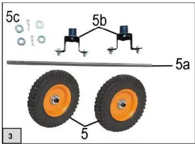
3. Scope of delivery
The following parts can be found in packaging. Ensure that all the parts are intact.
-
Manual
-
Generator unit
-
2 × support feet, front
-
Shaped metal parts
Rubber buffers - Nuts for rubber buffers (size 13)
- 2 x screws (size 10)
-
2 × nuts (size 10)
-
1 x wheel axle
-
4 x washer
-
2x split pin
-
2 × complete wheel
- Spark plug wrench
Depending on the purpose of the application, additional accessories may be necessary. Hint: If possible, keep the packing until the warranty period has expired.
4. Safety information

Please read through these operating instructions carefully and make yourself conversant with the control elements and the proper use of this product. We shall not be liable in the case of damage caused as a result of the nonobservance of instructions
and provisions of the present operating instructions. Any damage caused as a result of the nonobservance of the instructions and regulations contained in the present operating instructions shall not be covered by the warranty terms. Please keep these operating instructions in a safe place and hand them on together with the device should you ever dispose of
The device must not be used by children.
The device may be used by persons with reduced physical, sensory or mental capabilities or lack of experience and / or knowledge if they have been supervised or instructed in the safe use of the equipment and have understood the resulting hazards. Children are not allowed to play with the device. Keep the appliance and its cord out of reach of children.
Persons not conversant with the contents of these operating instructions must not use this device.
Store all the safety information and instructions for future use.
Note the meaning of the following pictograms.


Be cautious when operating electrical devices.
Caution: Voltage

You are required to read the operating instructions before placing the device in service!

Wear ear protection.

Do not operate the device near an open fire.

Protect the device from rain and moisture.

Do not use the device in closed rooms.
4.1. Warning and indication stickers
| Figure | Explanation |
| HEISS HOT AUSPUFF MUFFLER | CAUTION! Risk of burns due to hot exhaust |
| 95 dB | Guaranteed sound power level in DB (A) |
| 50 Hz | The AC connections have a frequency of 50 Hz. |
| OFF ON | Fuel cock position horizontal: Closed (OFF). Fuel cock position vertical: Opened (ON). |
| CHoke RUN | Cold start function: Set the lever to the left With warm engine: Lever to the right |
| max. min. | The oil filler opening is located here. Fill up to level indicated. Tank fill level: Max.: full Min.: empty |
| CPG 5500 NEV e24'2018/1628" 2018/989 SRB1/P0184100 (V) 7.6 KW Elektronik P 3000 W 3600 W Innenn 13A 230V-50Hz 400V-50Hz IP 23M 12V DC 8.3A Leistungsfaktor: 1 Gewicht: ca. 83 kg Max. Temperature: 40 °C Max. Hohe: 1000m UNN Max. Drehzahl: 3600 min Max. Leistung: 5500 Watt (52 mm) T.I.P. Industrie magazine Product Guide Standardisierte ZU O. T. Hörder Verwaltung | The serial number, article number and year of construction can be found on this type plate. Please make a note of the details on this plate so that they will still be available in the event of loss or damage. You will require this data when ordering spare parts or when making enquiries with regard to service information. |
| 7,6 kW | Combustion engine power: 7.6 kW |
| Elektronisch | The device has an electronic control unit |
| Pnnn 3600 W | Continuous power rating of electric generator: 3.6 kW |
| Innenn 13A | Rated current of electric generator: 13 A |
| 230V ~50Hz 400V ~50Hz | The device has Schuko sockets rated at 230 Volts, 400 Volts and 50 Hz. |
| IP 23M | Protection class of device: IP23M |
| Faulty electrical or electronic devices and/or devices to be disposed of must be handed over at the intended recycling places. |
4.2. Workplace safety
- Keep your work area clean and well-lit. Messy or dark work areas can lead to accidents.
- Do not operate the motorised device is an explosive environment, in which combustible liquids, gases or dusts are present. Motorised devices generate sparks, which can ignite the dust or fumes.
- Keep children or other people away when using the device.If you get distracted, you can lose control over the device.
4.3. Safety of persons
- Be attentive. Pay attention to what you are doing and use common sense when working with a motorised device.
-
Do not use a motorised device if you are tired or under the influence of drugs, alcohol or medication. A moment of inattention when using the motorised device can cause serious injuries.
-
Avoid unintentional start-up. Make sure that, the motorised device is switched off before you lift it or carry it.
- Clear away the adjustment tools or wrenches before you switch the motorised device on.If a tool or a wrench is left in a rotating part of the device, it can cause injuries.
- Wear suitable clothes. Do not wear loose clothes or jewellery. Keep hair, clothes and gloves away from moving parts. Loose clothes, jewellery or long hair can get caught in moving parts.
4.4. Safety when using combustion engines
- NEVER operate the machine indoors or in closed areas unless the exhaust gases are removed. Carbon monoxide in the exhaust gases is poisonous and can cause unconsciousness and death.
- Do not smoke or work in the immediate vicinity of the machine.
- Check the fuel lines and the tank for leaks and cracks at regular intervals.
- Do not refuel when the machine is switched on or still hot.
- Do not refuel near sparks, open fire or a smoking person - Risk of explosion!
- Never refuel a petrol or diesel engine in a room without sufficient ventilation. Fuel vapours are highly inflammable and poisonous.
- Do not overfill the tank and avoid spilling fuel when refuelling. If fuel spills, make sure that everything is dry before you start the engine.
- Make sure that the tank cap has been correctly and firmly closed after refuelling.
- Store the fuel in permitted containers only.
- A few parts of the combustion engine become very hot and can cause burns. Always be careful and observe the warning stickers on the device.
4.5. Maintenance safety
Regular maintenance and gentle care reduces the risk of possible malfunctions and contributes to lengthening the service life of your device.
- Make sure that repairs to the engine and machine are carried out by qualified personnel.
- Ensure that the engine switch is set to "OFF" before the safety equipment is dismantled or shifted.
- Always keep the machine clean and make sure that the stickers are legible. They contain important operating instructions and warn against risk. Replace the missing and illegible stickers.
- Do not use petrol or inflammable solutions to clean the machine. The fumes of the fuel or solutions can explode.
- Always store the machine properly. It must be placed in a clean and dry place, which is inaccessible to children.
- Danger to life! For avoiding an electric shock, the device is secured using circuit breakers, which are specially designed for this device. When replacing these switches, an identical switch must be used to prevent an electric shock.
4.6. Intended use of CPG 5500 NEV
The generator is intended for operating conventional electrical consumers such as chains of lights, electric service tools (drilling machines, electrical chain saws, compressors).
Electronic devices such as computers, TV units etc. must not be operated using a generator. In case of a doubt, contact the manufacturer of your device.
A qualified electrician must be consulted in advance for connecting the generator to stationary equipment such as heaters, household supply, air conditioners or for power supply to caravans. The critical point of an inductive consumer is the power consumption during switch-on. The power consumption can be up to 3 times the rated power. This must be taken into consideration at all times.
No liability is assumed for damages caused due to non-compliance with these instructions. You are required to read the operating instructions before using the device for the first time. In case of doubts regarding the connection and operation of the device, contact T.I.P. Technische Industrie Produkte GmbH. Please note that our devices have not been intentionally designed for commercial, handicraft-related or industrial use. We do not assume any warranty if the device is used in commercial, handicraft or industrial companies as well as for corresponding activities.
4.7. Risks and scope of prevention
| Risk | Description | Prevention |
| Direct electrical contact | Direct electrical contact with wet hands can cause electrical shocks. | Avoid contacting the device with wet hands and make sure the device has appropriate grounding. |
| Burns | Touching the exhaust can cause burns. | Let the devices cool down after operation. |
| Hearing impairments | Prolonged stay near a running generator can cause hearing impairments. | Always wear ear protection. |
| Contact, inhalation | Inhaling exhaust fumes can be fatal! | Never operate the device in closed rooms. |
| Fire or explosion | The fuel of the device can catch fire. | Never operate in inflammable environment. Never refuel when engine is running. No smoking. |
| Environmental hazards | Leaking of oil and fuel damages the environment. | Avoid leakage of these substances and use collecting trays during maintenance. |
| Breakage during operation | If the device is operated on a sloping surface, lubrication is not ensured and the device can be damaged. | Always operate on a flat surface. |
4.8. Generator circuit breaker
The generator is equipped with a combined thermal/magnetic circuit breaker. This circuit breaker allows higher currents to pass for a short period of time in order to allow 3-phase motors to start up. If the load is higher than the permitted value for a longer period of time, the circuit breaker disconnects the load from the generator. For this reason, check before first use whether the load connected lies within the permissible range as the circuit breaker could disconnect the load from the network after a certain time in order to protect the generator from overloading.
5. Assembly instructions
5.1. Assembly for mobile use
Take the CPG 5500 NEV out of the packaging and set it down at the intended assembly site. The machine must be horizontal. Remove dirt and dust so that the air cooling of the generator cannot draw in any foreign objects.
You should have the following aids at hand for installation:
2 x spanners (size 10)
2x spanners (size 13)
1 x needle-nosed pliers
Fit the support feet and the wheels (the required parts can be found under section 3, page 2).
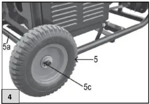
To fit the wheels (fig. 4, no. 5), first slide the wheel axle (fig. 4, no. 5a) through the holders on the underside of the generator and fit the wheels as shown in fig. 4. The washers must be fitted on the inside and on the outside. Fasten the wheels in place with the split pins provided.
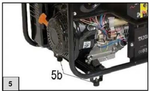
Screw the support feet onto the bottom frame bars
(fig.5).
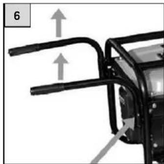
Turn the handles towards you and pull upwards until the latching lug latches into the hole in the guide
If the generator is to be used for an extended period of time in one place, it is recommended to fold the handles back into the frame. To do so, press the latching lug and turn the handle towards the generator.
6. Putting into operation
The generator is equipped with a low-oil safety feature. This convenient technology automatically stops the engine when the engine oil falls below the required minimum level. Because the generator is delivered without operating materials, it is essential that it is filled with engine
oil before first use. The engine can be started only when a sufficient quantity of the oil has been filled. When filling with the operating materials, observe all of the relevant instructions and specifications cited in these operating instructions.
6.1. Tests before start-up
Check the battery connection
Before start-up, the “- terminal” of the battery must be connected. Otherwise, it is not possible to operate the generator. The “+ terminal” is already connected and insulated using a terminal cover.

Note:
When connecting the terminals, first connect the "+" terminal" and then the "terminal".
When disconnecting the terminals, first disconnect the "terminal" and then the "+ terminal".
Check the engine oil level
Note: Always switch the engine off before checking the engine oil level.
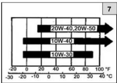
Use a suitable 4-stroke oil for diesel engines. The use of SAE 10W-30 is recommended for general use in different temperature ranges. The other viscosities stated in the table can be used if the average temperature in the area of application lies in the stated range.
Check the oil level
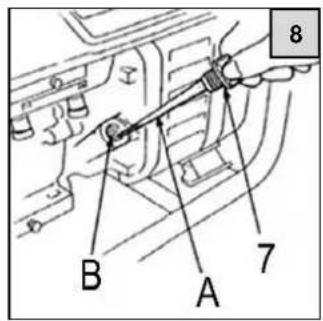
- Remove the oil filler screw and clean the dipstick using a clean cloth.
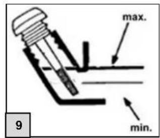
- Insert the filler plug with dipstick back into the oil filler port (fig. 8. B) without turning it. Take the dipstick out again and check the oil level.
- If the oil level is below the bottom end of the dipstick (min.) add engine oil until the oil reaches the top mark (max.).
- Insert the dipstick correctly and screw it on again.
Check the fuel level
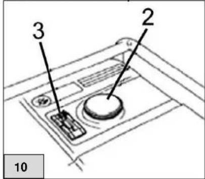
- Check the fuel gauge (fig. 10 no. 3) and fill the fuel tank if the fuel level is too low.
- Use only Petrol or E10, Diesel can damage the generator considerably.
- Remove the tank cap (fig. 10 no.2)
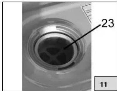
- Fill with fuel to a maximum level of the bottom of the filter insert (fig. 11, no. 23).
- Close the tank cap.
Earth the generator before use
Make sure that the generator is earthed by pushing a metal rod into the ground and connecting it with earth connection via a cable. (* = not included in scope of delivery.)
6.2. Starting the engine with the E-starter
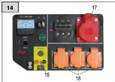
- Disconnect all consumers from the power supply (.fig. 14, no.17, 18 & 19)
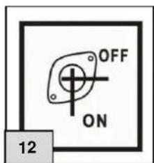
- Set the fuel cock at the fuel filter to "open" ("ON"). Please see figure 12.
- Set the choke lever to (fig.13) "Pulled" ("1").
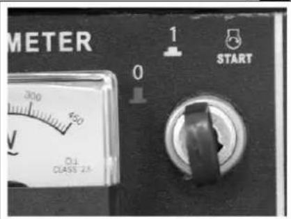
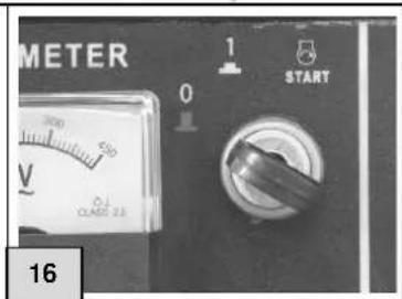
- Turn the ignition key switch (fig. 13) to "1".
After you perform this step, you can now start the generator.
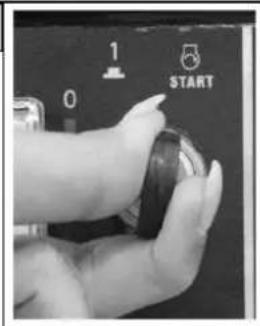
To do this, insert the ignition key provided in the ignition key switch (fig. 13) and along the direction "Start". Let go of the ignition key after max. 10 seconds and the engine should now run.
If the engine does not start after 10 seconds, you should wait for at least 1 minute before the next attempt. This process may only be repeated a maximum of 3 times and then the electric starter must be allowed to cool down for at least 15 minutes. Disregarding this can cause the damage to the starter and/or engine. Do not attempt to start the engine when it is already running!
13
- After a brief warm-up phase, slide the choke back again. Now you can set the changeover switch (fig. 2, no. 21) to the operating voltage your require 230V or 400V (230V = top;400V = bottom)
- Insert the plug of the consumer into the corresponding socket of the electric generator. Switch the circuit breaker on. Then switch on the consumers on after the other.
Observe the running of the engine as well as the colour of the exhaust gas once started. The engine running should settle down after a few minutes. The voltmeter should show 230V or 400V .

The 12 V outlet of the generator is not a voltage-controlled connection and hence is not suitable for charging batteries. The installed battery must not be connected to the 12 V connection of the electric generator because it is separately charged via an alternator.
6.3. Starting the motor with the pull starter
- Disconnect all consumers from the power supply (fig. 14, 17, 18 & 19) and switch the ignition to "ON".
- Set the fuel cock at the fuel filter to "open" ("1"). Please see figure 12.
- Set the choke lever to "Pulled" ("1").
- Set the ignition lock (Fig. 13) to start.
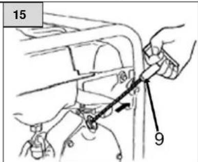
- Carefully pull the pull-cord starter (fig. 15, no. 9) until you can feel a light resistance, then pull it

Attention! Injury!
A setback can occur unexpectedly on the pull starter, which suddenly blocks the rope.
quickly and forcefully.
After a brief warm-up phase, return the choke lever. Corresponding devices can now be connected and started. Note that only the 230V outlets or the 400V outlet can be operated at any given time.
Observe the motor operation and the color of the exhaust gas after the drain. The motor operation should stabilize after a few seconds. The voltmeter should display 230V
6.4. Stopping the engine
- Disconnect all the electrical devices from the mains voltage before you stop the generator.
- Turn the ignition key to "0" (fig. 16)
- Set the fuel cock to "Closed" ("0"). (fig. 12)

Note:
If you have to switch the engine off immediately due to an emergency, set the ignition key and all the other switches to "OFF".
6.5. Operating options of the generator
- Operate the device as described in these instructions only! Any other use is considered misuse and can cause hazardous situations.
- When connecting several consumers to the generator, first connect the consumers with highest power consumption and then with lower power consumption. When using extension cables or mobile distribution networks, a maximum length of 60m must not be exceeded for a cross-sectional area of 1.5mm^2 . A length of 100m must not be exceeded for a cross-sectional area of 2.5mm^2 . Use flexible hard rubber extension cables only, which corresponds to the brief design description H07RN-F.

Attention!
Electrical devices and equipment, such as extension cables, sockets, connected consumers etc., may be used only if they are not damaged.
The engine can produce its rated power only in standard conditions mentioned in the technical data. They are defined as followed:
- Installation height approx. 1000m above normal null
Air temperature approx. 40^
Rel. Humidity approx. 60%
If these values are exceeded, a reduced power is necessary for the electric generator - 1% reduced power for installation height of each 100m above the aforementioned installation height and exceeding of air temperature above 40^ , approx. 4% pro 10^ .
- Certain electrical devices and motor-powered devices require a higher power than their nominal rated power for a short period of time due to their design.. The following table offers an overview of different device examples.
| Ratio of Effective power to | Consumer | Power consumption | |||
| Starting power | Rated power | Starting power | Rated power | Effective power | |
| x1 | x1 | Light bulb TV | 100 W | 100 W | 100 W |
| x1,5 | x1 | Fluorescent tubes | 60 W | 40 W | 40 W |
| x3-5 | x2 | Refrigerator Fan | 900-1500 W | 600 W | 300 W |
Rated power: The power of an electric consumer that it can consume, which is specified by the manufacturer, is called as rated power.
Effective power: The actually used energy per time of an electric consumer during operation is called as the effective power.
Starting power: The power consumption of an electric consumer that often increases during the switch on or start phase is called the starting power.

Connection for feeding electrical power into existing networks shall only be implemented by specialist personnel and after prior approval by the energy supply company.
The substitute generator is suitable for feeding electrical power into an existing distribution network only in case of failure of general power supply.
Measures must be taken so that interconnection is safely prevented after a recovery from power failure.
Measures for safety against hazardous body currents
When feeding electrical power into an existing distribution network, the measures for safety against hazardous body currents must be adapted to the existing safety measures of the existing distribution network.
7. Maintenance and cleaning

Note:
Ensure that the ignition key switch is set to "0", the "- pole" of the battery is disconnected and the spark plug connector pulled off, before starting maintenance.
7.1. Maintenance intervals
| Element\Maintenance interval To be carried out depending on which criteria occurs. (Period or operating hours) | Daily | After the first month or 10 h | Every 3 months or 30 h | Every 6 months or 50 h | Every 12 months or 100 h | |
| Engine oil | Inspection (see 6.1.) | ● | ||||
| Change (See 7.2.) | ● | ● | ||||
| Air fil- ter | Inspection (See 7.3.) | ● | ||||
| Cleaning (See 7.3.) | ● | |||||
| Change | ● | |||||
| Cleaning the fuel filter (See 7.5.) | ● | |||||
| Adjusting the valve clearance * | ● | |||||
| Cleaning combustion chamber and valves * | ● | |||||
| Checking the fuel line (replace if necessary) * | ● | |||||
| Exhaust * | Cleaning after 100 operating hours | |||||
- Get this work carried out by authorised personnel.
7.2. Oil change
Empty the oil as long as the engine is still warm in order to guarantee a quick and complete drainage.
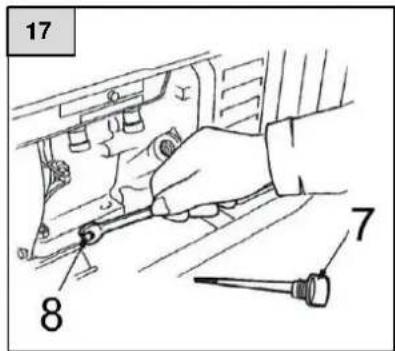
- Remove the oil drain screw (fig. 17, no. 8) and the oil filler screw (fig. 17, no. 7) and drain the oil into a suitably sized container. Retighten the screw including a new seal.
- Fill the engine oil with the recommended quality (see paragraph. 6.1) and check the oil level.
Oil fill capacity: 1.1 I

Caution: Prolonged or repeated skin contact with used oil can cause skin cancer. Although the risk is very low unless you come in contact with used oil on a daily basis, you should wash your hands with soap and water as soon as possible after coming in contact with waste oil.
Note: Dispos of the waste oil in an environmentally responsible way. We recommend handing over the waste oil in a closed container to a local disposal company for recycling. You can find this under, e.g. http://www.wer-entsorgt-was.de/entsorger_suche.html Do not dispose of the waste oil in the trash or by pouring it out.
7.3. Maintenance of air filter
A dirty air filter limits air flow into the engine. Maintain the air filter regularly to prevent the generator from malfunctioning. If you use the generator is very dusty areas, you must clean the air filter more often. Carry out a visual inspection for dirt and damages before every use.

Warning! Never use petrol or solvent with low flash point for cleaning the air filter. It can result in fires or explosions. Follow the instructions and safety information on the packaging of the solvent
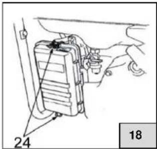
- Loosen and remove the air filter cover. You can then remove the air filter from the housing.
- Wash the air filter in non-flammable solvent and dry it carefully. The solvent should be especially suitable for air filter cleaning.
- Reinsert the air filter and the air filter cover and screw it on using fastening screws.
Caution: Never operate the generator without the air filter. Doing so can cause major engine damage and quick wearing of the engine.
7.4. Spark plug maintenance
Recommended spark plugs: F6TC, F7TC
In order to guarantee flawless operation of the engine, spark plugs with the correct electrode gap and free of residue must be used.
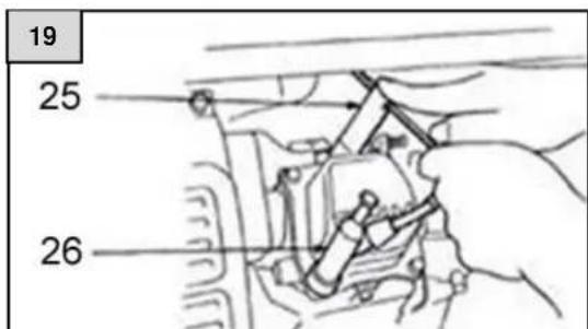
- Pull off the spark plug connector (fig. 19, no. 26).
- Remove any dirt from the spark plug recess.
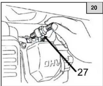
- Remove the spark plug (fig. 20, no. 27) with the help of the spark plug wrench (fig. 19, no. 25) provided.
- Carry out a visual check of the spark plug. Dispose of the spark plug if the insulation is cracked or chipped. If you wish to continue using the spark plug, clean it with a wire brush.
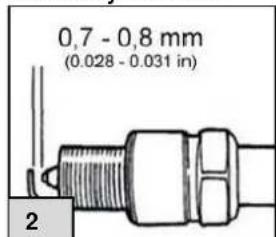
- Check the electrode gap (see fig. 21) with a feeler gauge (not included in the delivery). The gap should be 0.7 - 0.8 mm . If necessary, correct the gap by bending the earth electrode.
- Screw the spark plug in by hand in order to avoid damaging the thread.
- After manually screwing in a new spark plug, this should be tightened a further 180^ with the spark plug wrench provided in order to ensure that the spark plug is correctly seated.
If a used spark plug is to be reinserted for further use, an Abb. 21additional 45^ to 90^ turn will be required after initial insertion.

Caution!
The spark plug must be tightly seated. If the spark plug is not tightly seated it can become very hot and possibly damage the generator. Use only the recommended spark plugs.
7.5. Maintenance of battery
Charge and check the battery when removed. Remove the connection cables and insulate the contacts carefully to avoid a short-circuit. If you do not want to operate the generator for a long time, remove the battery and keep it in a safe and dry place. Charge the battery at certain time intervals to maintain its functionality.
8. Transport and storage

Warning! Set the starter switch to "OFF" ("0") during transportation of the generator. Always keep the generator horizontal to avoid fuel leakage. Fuel vapours or spilled fuel can catch fire.
The tilting angle of the device should never be more than 15^
Preparation for long-term decommissioning / storage of device:
- Make sure that the storage area is free from excess humidity and dust.
- Drain the fuel:
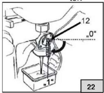
Turn the fuel cock to "OFF" ("0") (Fig. 22, no. 12). Remove the fuel hose from the fuel cock. Turn the fuel cock to "ON" ("1") and fill the fuel in a suitable container using a funnel. After the fuel tank has been completely emptied, shift the fuel hose back to the outlet of the fuel cock.
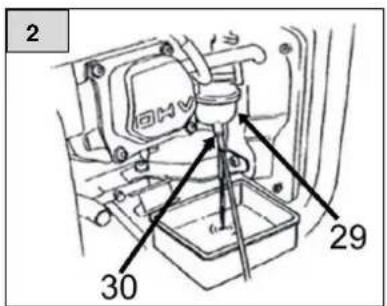
- Loosen the filter glass (fig. 23, no. 30) of the fuel filter and empty the residual fuel from the filter (fig. 23, no. 29) into a suitable container.

If the fuel can no longer be used due to impurities, dispose of it in an environmentally responsible way.
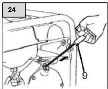
- Unscrew the spark Plug and pour about 20ml of engine oil through the spark plug hole. Pull gently on the pull starter (Fig. 24, No. 9) until you feel a resistance. At this point, the piston is raised in the frame of the compression hub, the inlet and outlet valves are closed and some oil is distributed in the engine. Screw the spark plug back in. Storage of the motor in this position prevents corrosion inside the appliance.

Note:
The starter battery should be disconnected for transportation and storage. The battery should be charged at regular intervals during storage / over winter.
9. Troubleshooting
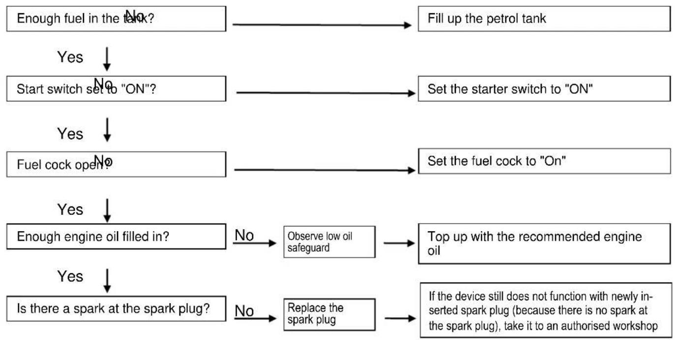
Engine does not start:
!Warning!
Ensure that there is no spilled fuel in the vicinity of the spark plug. Spilled fuel can ignite.
Use insulated pliers or at least gloves to position the spark plug in order to protect yourself from electric shock.
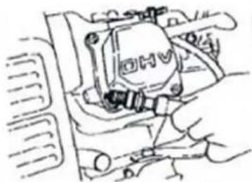
Checking the spark plug
- Remove the spark plug connector and clean the spark plug of dirt.
- Remove the spark plug and fit the spark plug connector to the spark plug again.
- Place the earth electrode against the cylinder head.
- Pull the pull-cord starter. Sparks should jump between the electrodes.
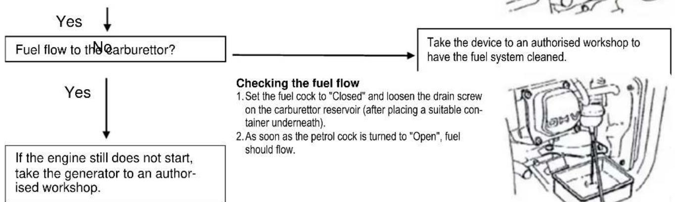
No electrical power at the connections:

10. Warranty
The present device was manufactured and inspected according to the latest methods. The seller warrants for faultless material and workmanship in accordance with the legal regulations of the country in which the device was purchased. The warranty period begins with the day of the purchase and is subject to the provisions below:
Within the period of warranty, all defects which are to be attributable to defective materials or manufacturing will be eliminated free of charge. Any complaints are to be reported immediately upon their detection.
The warranty claim becomes void in the case of interventions undertaken by the purchaser or by third parties. Damage resulting from improper handling or operation, incorrect setting-up or storage, inappropriate connection or installation or Acts of God or other external influences are excluded from warranty.
Parts being subject to wear and tear are excluded from warranty.
All parts were manufactured using maximum care and high-quality materials and are designed for a long lifecycle. It should be understood, however, that the wear and tear depends on the kind of use, the intensity of use and the internals of maintenance. Complying with the installation and maintenance information contained in the present operating instructions will therefore considerably contribute to a long lifecycle of these wearing parts.
In case of complaints, we reserve the option of repairing or replacing the defective parts or replace the entire device. Replaced parts will pass into our property.
Claims for liquidated damages are excluded unless they are caused by wilful acts or negligence on the side of the manufacturer.
The warranty does not provide for any claims beyond those referred to above. The warranty claim has to be evidenced by the purchaser in the form of the submission of the sales receipt. The present warranty commitment is valid in the country in which the device was purchased.
Please note:
- Should your device fail to function properly, please verify first whether an operating error or another cause is present which cannot be attributed to a defect of the device.
- In case you have to take or send in your defective device for repair, please be sure to enclose the following documents:
Sales receipt (sales slip).
- A description of the occurring defect (a description as accurate as possible will expedite the repair work).
- In case you have to take or send in your defective device for repair, please remove any attached parts which do not belong to the original condition of the device. If any attached parts of this kind should be missing upon the return of the device, we shall not be liable for them.
11. How to order spare parts
The fastest, most simple and cheapest way of ordering spare parts is through the internet. On our website www.tip-pumpen.de you will find a convenient spare part shop where you can order spare parts with just a couple of clicks. In addition, this is also the place where we publish comprehensive information and valuable tips on our products and accessories, introduce new devices and present current trends and innovations in the range of pump technology.
12. Service
In the case of warranty claims or malfunction, please contact your point of sale.
A current operating manual is available as required as a PDF file via e-mail: service@tip-pumpen.de.
In case of return or complaint regarding your device remember that you are required to close the side vents of the battery using tape and to disconnect the connection cable of the minus terminal before dispatch in accordance with the ADR Directive 598. Make sure that the plus terminal is properly secured using a terminal cover.
Disposal and recycling of packaging
The device is provided in a package to avoid damages during transport. This package is made of raw materials and hence can be reused or recycled.
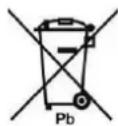
Law on the new regulations for waste legislation product responsibility for batteries and accumulators
Batteries are supplied with most electrical devices. As part of selling these batteries, we are obliged as a retailer to inform our customers of the following in accordance with the battery legislation:
Please dispose of used batteries as prescribed by law at a communal collection point or hand them in to a dealer in your area free of charge so that raw materials and possible pollutants can be disposed of properly; disposing of batteries in household refuse is strictly prohibited by the battery legislation. You can hand batteries that are or were part of our range in to us free of charge at the aforementioned address after use or you can send them back to us by post with the correct postage paid. This applies to quantities that the end user would normally want to dispose of.
The crossed out rubbish bin that is printed on all battery packaging advises of this obligation. Furthermore, you can also find the chemical symbols for the substances cadmium (Cd), lead (Pb) or mercury (Hg) there if they are present in quantities above the limit values.
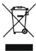
For EC countries only
Please do not dispose of electrical appliances in the regular domestic waste!
According to the European Directive 2012/19/EU regarding waste electrical and electronic equipment and the implementation of that directive into national law, electrical devices have to be collected separately and disposed of in an environmental-suitable manner after the end of their life cycle. Should you have any questions, please contact your local waste disposal company.
Chere cliente, cher client,
Service Email: service@tip-pumpen.de
service@tip-pumpen.de.
D-74915 Waibstadt / Germany
Tel.: +49 (0) 7263 9125-0
Fax: +49 (0) 7263 9125-85
Website: http://www.crosstools.de