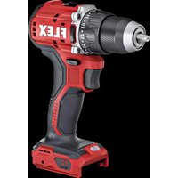
DD 2G 18.0-EC LD - Drill Flex - Free user manual and instructions
Find the device manual for free DD 2G 18.0-EC LD Flex in PDF.


User questions about DD 2G 18.0-EC LD Flex
0 question about this device. Answer the ones you know or ask your own.
Ask a new question about this device
Download the instructions for your Drill in PDF format for free! Find your manual DD 2G 18.0-EC LD - Flex and take your electronic device back in hand. On this page are published all the documents necessary for the use of your device. DD 2G 18.0-EC LD by Flex.
USER MANUAL DD 2G 18.0-EC LD Flex
en Original operating instructions....16
natural_image
Technical line drawing of a mechanical device with an arrow indicating motion direction (no text or symbols)C
text_image
Technical diagram of a battery with labeled parts and directional arrows indicating components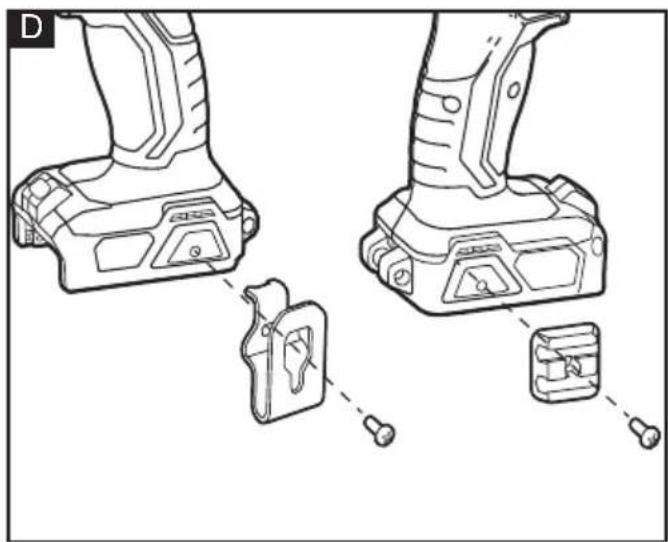
natural_image
Technical line drawing of a mechanical component with two views and a close-up detail (no text or symbols)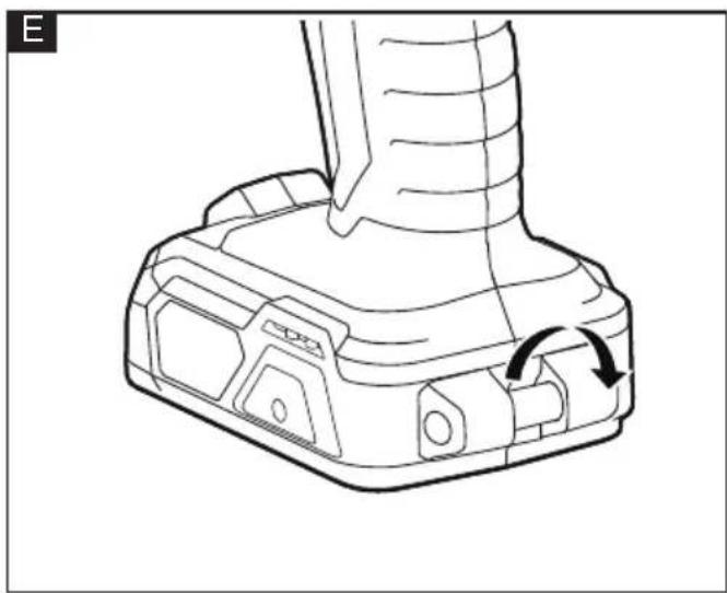
natural_image
Technical line drawing of a mechanical component with a curved arrow indicating rotation (no text or symbols)
natural_image
Illustration of a hand holding a cylindrical device with an open lock and arrow indicating rotation (no text or symbols)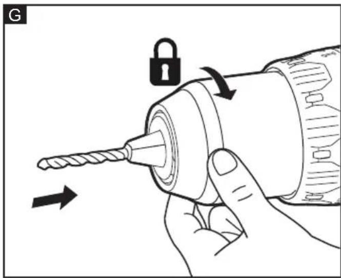
natural_image
Illustration of a hand using a drill bit to adjust a screw with an open lock (no text or symbols)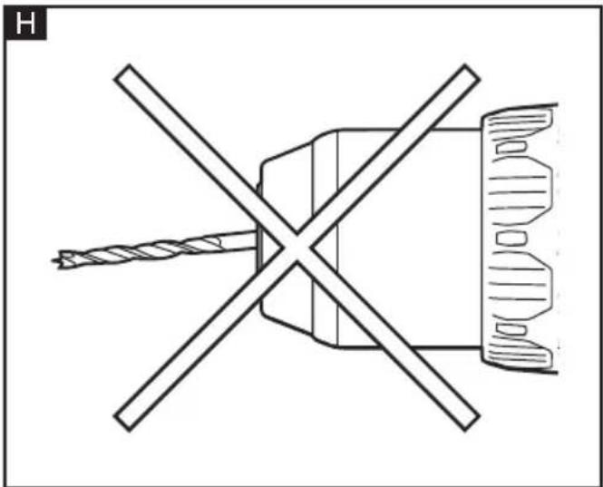
natural_image
Technical line drawing of a mechanical component with intersecting lines and a central cross (no text or symbols)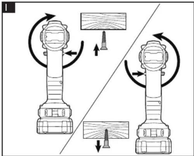
text_image
Diagram illustrating the working principle of a flashlight mechanism, showing rotating components and directional arrows.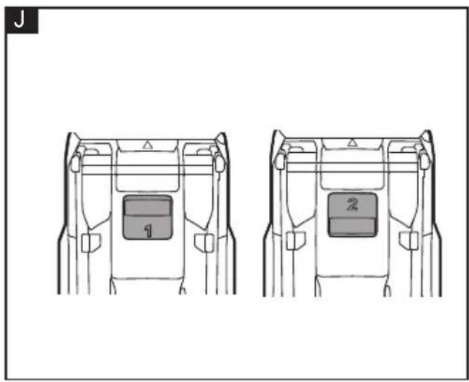
natural_image
Technical line drawing of two mechanical components with labeled parts (1 and 2), no readable text or symbols present.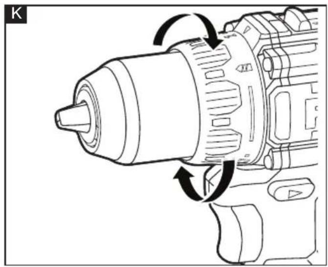
natural_image
Technical line drawing of a mechanical power tool with circular motion arrows indicating rotation (no text or symbols)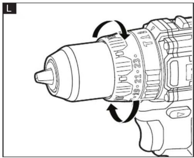
natural_image
Technical line drawing of a drill bit with rotational arrows indicating motion (no text or symbols)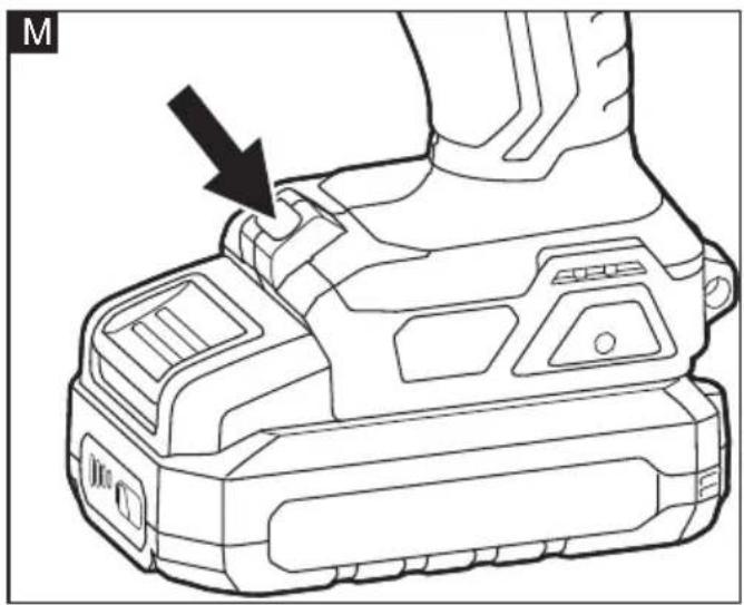
natural_image
Technical line drawing of a mechanical device with an arrow pointing to a component (no text or symbols present)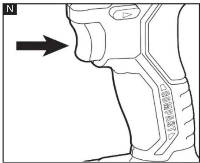
text_image
N G00001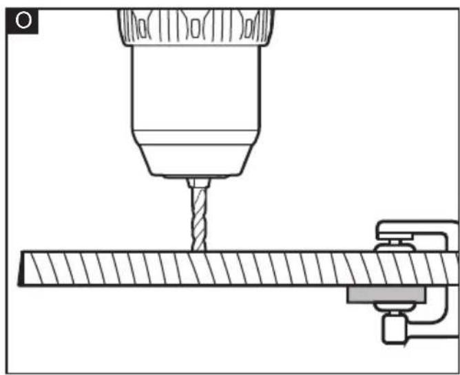
natural_image
Technical line drawing of a drill bit machining a workpiece (no text or symbols)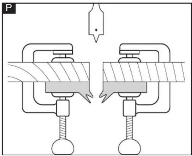
natural_image
Mechanical assembly diagram showing two clamping arms with a tool and a hanging component (no text or symbols)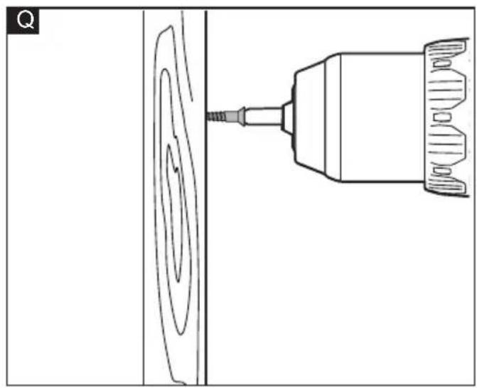
natural_image
Technical line drawing of a drill bit with concentric circular patterns and a tool (no text or symbols)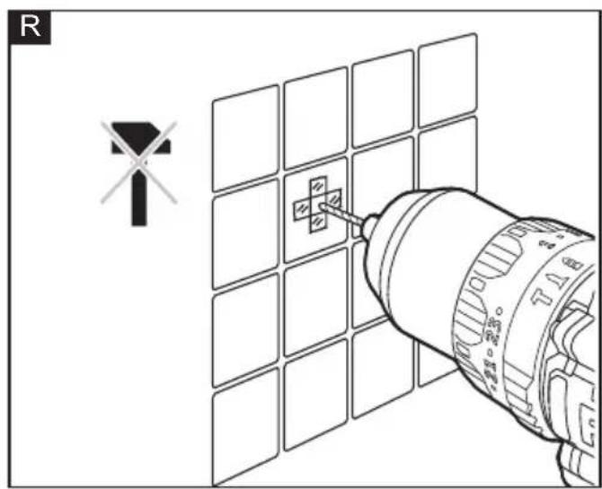
text_image
R T16 T16 T16 T16 T16 T16 T16 T16 T16 T16 T16 T16 T16 T16 T16 T16 T16 T16 T16 T16 T16 T16 T16 T16 T16 T15 T15 T15 T15 T15 T15 T15 T15 T15 T15 T15 T15 T15 T15 T15 T15 T15 T15 T15 T15 T15 T15 T15 T15 T15 T14 T14 T14 T14 T14 T14 T14 T14 T14 T14 T14 T14 T14 T14 T14 T14 T14 T14 T14 T14 T14 T14 T14 T14 T14 T13 T13 T13 T13 T13 T13 T13 T13 T13 T13 T13 T13 T13 T13 T13 T13 T13 T13 T13 T12 T12 T12 T12 T12 T12 T12 T12 T12 T12 T12 T12 T12 T12 T12Symbols used in this manual

WARNING!
Denotes impending danger. Non-observance of this warning may result in death or extremely severe injuries.

CAUTION!
Denotes a possibly dangerous situation. Non-observance of this warning may result in slight injury or damage to property.

NOTE
Denotes application tips and important information.
Symbols on the power tool
V
Volts
/min Rotation rate

To reduce the risk of injury, read the operating instructions!
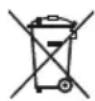
Disposal information for the old machine (see page 22)!
For your safety

WARNING!
Before using the power tool, please read the follow:
- these operating instructions,
- the "General safety instructions" on the handling of power tools in the enclosed booklet (leaflet-no.: 315.915),
– the currently valid site rules and the regulations for the prevention of accidents.
This power tool is state of the art and has been constructed in accordance with the acknowledged safety regulations.
Nevertheless, when in use, the power tool may be a danger to life and limb of the user or a third party, or the power tool or other property may be damaged.
The cordless drill driver/hammer drill may be used only
-asintended,
- in perfect working order.
Faults which impair safety must be repaired immediately.
Intended use
The cordless drill driver/hammer drill is intended
– for commercial use in industry and trade,
- for drilling holes, drilling wood, drilling metal, driving screws and drilling masonry (this only for hammer drill).
Safety instructions for drill driver/hammer drill

WARNING!
Read all safety warnings, instructions, illustrations and specifications provided with this power tool. Failure to follow all instructions listed below may result in electric shock, fire and/or serious injury. Save all warnings and instructions for future reference.
Drill driver
- Hold the power tool by insulated gripping surfaces, when performing an operation where the cutting accessory or fastener may contact hidden wiring. The cutting accessory or fastener contacting a "live" wire may make exposed metal parts of the power tool "live" and could give the operator an electric shock.
- Secure the work piece. Clamping devices or a vise will hold the work piece in place better and more safely than holding it by hand.
- Do not drill, fasten or break into existing walls or other blind areas where electrical wiring may exist. If this situation is unavoidable, disconnect all fuses or circuit breakers feeding this worksite.
■ Position yourself to avoid being caught between the tool or walls or posts.
Should the bit become bound or jammed in the work, the reaction torque of the tool could crush your hand or leg.
■ Always wait until the machine has come to a complete stop before placing it down. The tool insert can jam and lead to loss of control over the power tool.
■ When working with the power tool, always hold it firmly with both hands and assume a secure stance. The power tool is guided more securely with both hands.
Hammer drill
■ Wear ear protectors when impact drilling. Exposure to noise can cause hearing loss.
- Hold the power tool by insulated gripping surfaces, when performing an operation where the cutting accessory or fastener may contact hidden wiring. The cutting accessory or fastener contacting a "live" wire may make exposed metal parts of the power tool "live" and could give the operator an electric shock.
- Secure the work piece. Clamping devices or a vise will hold the work piece in place better and more safely than holding it by hand.
- Do not drill, fasten or break into existing walls or other blind areas where electrical wiring may exist. If this situation is unavoidable, disconnect all fuses or circuit breakers feeding this worksite.
■ Position yourself to avoid being caught between the tool or side handle and walls or posts. Should the bit become bound or jammed in the work, the reaction torque of the tool could crush your hand or leg.
Safety instructions when using long drill bits:
■ Never operate at higher speed than the maximum speed rating of the drill bit.
At higher speeds, the bit is likely to bend if allowed to rotate freely without contacting the workpiece, resulting in personal injury.
■ Always start drilling at low speed and with the bit tip in contact with the workpiece. At higher speeds, the bit is likely to bend if allowed to rotate freely without contacting the workpiece, resulting in personal injury.
■ Apply pressure only in direct line with the bit and do not apply excessive pressure. Bits can bend causing breakage or loss of control, resulting in personal injury.
Noise and vibration
The noise and vibration values have been determined in accordance with EN 62841. The A evaluated noise level of the power tool is typically:
- Sound pressure level L_pA :
DD 2G 18.0-EC LD 78 dB(A)
PD 2G 18.0-EC LD 77 dB(A)
- Sound power level L_WA :
DD 2G 18.0-EC LD 89 dB(A)
PD 2G 18.0-EC LD 88 dB(A)
- Uncertainty: K = 5 dB.
Total vibration value:
- Emission value a_h :
DD 2G 18.0-EC LD 1.02 m/s ^2
PD 2G 18.0-EC LD 0.78 m/s ^2
– Uncertainty: K = 1.5 m/s

CAUTION!
The indicated measurements refer to new power tools. Daily use causes the noise and vibration values to change.

NOTE
The vibration emission level given in this information sheet has been measured in accordance with a measurement method standardised in EN 62841 and may be used to compare one tool with another.
It may be used for a preliminary assessment of exposure. The specified vibration emission level represents the main applications of the tool. However, if the tool is used for different applications, with different cutting accessories or poorly maintained, the vibration emission level may differ. This may significantly increase the exposure level over the total working period.
To make an accurate estimation of the vibration exposure level, it is also necessary to take into account the times when the tool is switched off or running but not actually in use.
This may significantly decrease the exposure level over the total working period. Identify additional safety measures to protect the operator from the effects of vibration such as: maintain the tool and the cutting accessories, keep the hands warm, organisation of work patterns.

CAUTION!
Wear ear defenders at a sound pressure above 85 dB(A).
Technical data
| Tool | DD 2G 18.0-EC LD | PD 2G 18.0-EC LD | |
| Type Drill Driver | Percussion Drill Driver | ||
| Rated voltage | Vdc 1 | 8 | |
| No-load speed | r.p.m | 0-500 / 0-1800 | |
| Chuck capacity | mm 1 | .5-13 | |
| Max. drill diameter for metal | mm 1 | 3 13 | |
| Max. drill diameter for wood | mm 5 | 2 52 | |
| Max. drill diameter for masonry | mm N | /A 13 | |
| Torque, max.- Soft screw-driving case-Hard screw-driving case | Nm Nm | 3565 | |
| Impact rate b | pm N | /A | 0-8000 / 0-28800 |
| Clutch settings | 18+ | 24+ | |
| Weight according to"EPTA Procedure 01/2003"(without battery) | kg 1.1 | 1 1.195 | |
| Battery | AP 18.0/2.5AP 18.0/5.0AP 18.0/8.0 | ||
| Weight of battery | kg | AP 18.0/2.5AP 18.0/5.0AP 18.0/8.0 | 0.40.71.1 |
| Working temperature | -10°-40°C | ||
| Storage temperature | < 50°C |
| Charging temperature | 4~40°C |
| Charger CA 1 | 0.8/18.0, CA 18.0-LD |
Overview (see figure A)
The numbering of the product features refers to the illustration of the machine on the graphics page.
- Torque-adjustment ring
- Keyless chuck
- Chuck jaws
- Variable-speed trigger switch
- LED light
-
Two-speed gear shifter
-
Direction preselector switch (forward/center-lock/reverse)
-
Soft grip
-
Strap fixing
For attaching a wrist strap (not included) in order to reduce the chances of dropping your tool.
-
Function-selection ring
Only for PD 2G 18.0-EC LD -
Removable belt clip
-
Removable bit bracket
Operating instructions

WARNING!
Remove the battery before carrying out any work on the power tool.
Before switching on the power tool
Unpack the cordless drill driver/hammer drill and check that here are no missing or damaged parts.

NOTE
The batteries are not fully charged on delivery. Prior to initial operation, charge the batteries fully. Refer to the charger operating manual.
Inserting/replacing the battery
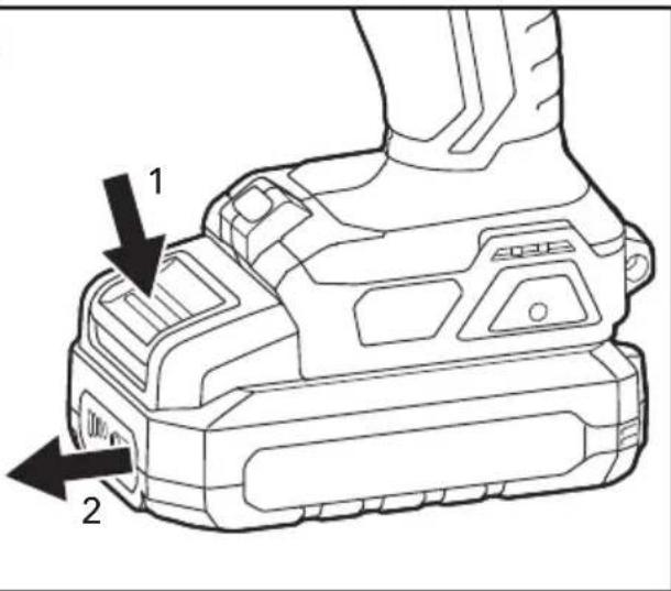
■ Press the charged battery into the power tool until it clicks into place (see figure B).
■ To remove, press the release button and pull out the battery (see figure C).

CAUTION!
When the device is not in use, protect the battery contacts. Loose metal parts may short circuit the contacts; explosion and fire hazard!
Removable belt clip and bit bracket
■ Remove the battery pack from the tool.
■ Align the hole of the belt clip 11 and bit bracket 12 with the threaded hole on the base of the tool (see figure D).
■ Insert the fastening screw and securely tighten the screw with a screwdriver (not included).
Strap fixing
- Strap fixing is provided to attach a wrist strap (not included) in order to reduce the chances of dropping your tool. Wrap the strip around your hand when carrying the tool (see figure E).
Install and remove bits

CAUTION!
Before carrying out any work on the power tool, move the direction preselector switch 7 to the middle position.
■ Place the direction selector switch 7 in the center position to lock the trigger switch 4.
■ Remove the battery pack. Rotate the chuck 2 counterclockwise, as shown in Figure F, to open the chuck jaws 3.
■ Insert a bit as far as it will go and rotate the chuck 2 clockwise and securely tighten by hand. (See figure G)
■ To remove the bit, rotate the chuck 2 counterclockwise to open the chuck jaws 3 and remove the bit.

WARNING
Make sure to insert the drill bit straight into the chuck jaws. Do not insert the drill bit into the chuck jaws at an angle and then tighten the chuck as shown in Figure H This could cause the drill bit to be thrown from the tool, resulting in possibly serious personal injury or damage to the chuck.

WARNING
The bit may be hot after prolonged use. Use protective gloves when removing the bit from the tool, or first allow the bit to cool down.
Direction preselection (see figure I)

CAUTION!
Change the direction of rotation only when the power tool is stopped.
Move the direction preselector switch 7 to the required position:
■ Position the direction preselector switch 7 to the far left of the tool to drive screws in or tighten screws.
■ Position the direction preselector switch to the far right of the tool to remove screws or loosen screws.
■ Position the direction preselector switch in the "OFF" (center-lock) position to help reduce the possibility of accidental starting when not in use.

NOTE
The drill driver/hammer drill will not run unless the direction-of-rotation selector is engaged fully to the left or to the right.

WARNING!
Battery tools are always in operating condition. Therefore, the direction preselector switch should always be locked in the center position when the tool is not in use or when carrying it at your side.
Two-speed gear shifter (see figure J)
The shifter 6 is located on the top of the tool and allows to switch between gears "1" and "2".
a. Gear "1" provides higher torque and slower speeds for heavy-duty work or for driving screws, drilling large diameter holes, or tapping threads. Use the mode "1" for starting holes without a center punch, drilling metals or plastic, drilling ceramics, or in applications requiring a higher torque.
b. Gear "2" provides lower torque and faster speeds for hammer drilling (PD 2G 18.0-EC LD only) or lighter drilling work. The gear "2" speed is more suitable for drilling wood and wood composites and for using abrasive and polishing accessories.
NOTICE: To prevent gear damage, always allow the tool to come to a complete stop before changing gears.
Function-selection ring (PD 2G 18.0-EC LD only) and torque-adjustment ring

WARNING!
Do not adjust the torque or function-selection ring when the tool is running.
Your tool is equipped with a function-selection ring (PD 2G 18.0-EC LD only) and torque adjustment ring for various applications. Move the ring depending on the requirements of your task.
The proper setting depends on the job and the type of bit, fastener, and the material you will be working on. In general, use greater torque for larger screws. If the torque is too high, the screws may be damaged or broken.
DD 2G 18.0-EC LD (see figure K):
Your drill features 18 torque settings for driving and 1 drilling setting. Output torque will increase as the ring is rotated from 1 to 18.
Adjust the torque by rotating the torque-adjustment ring. The higher the torque setting, the more force the tool produces to turn an object.
The drilling setting will lock the clutch to permit drilling and other heavy-duty applications.
PD 2G 18.0-EC LD (See figure L):
Your hammer drill features 24 torque settings, 1 drilling setting, and 1 hammer drilling setting. Output torque will increase as the ring is rotated from 1 to 24.
The Drill setting will lock the clutch to permit (non-hammer) drilling and other heavy-duty applications.
The Hammer Drilling setting will lock the clutch to permit hammer drilling only.
NOTICE: Do not use the hammer drilling setting for drilling in wood, metal, ceramic, and plastic to prevent the drill/screw bit from being damaged.
LED light (see figure M)
Your tool is equipped with an LED light 5, located on the base of the tool. This provides additional light on the surface of the work piece for operation in lower-light areas.
The LED light 5 will automatically turn on with a slight squeeze on the variable-speed trigger switch 4 before the tool starts running, and will turn off approximately 10 seconds after the variable-speed trigger switch 4 is released.
The LED light will rapidly flash when the tool and/or battery pack becomes overloaded or too hot, and the internal sensors will turn the tool off. Rest the tool for a while or place the tool and battery pack separately under air flow to cool them.
The LED light will flash more slowly to indicate that the battery is at low-battery capacity. Recharge the battery pack.
Switching on the power tool (see figure N)
■ To switch the power tool on:
Press the trigger switch 4.
The variable-speed trigger switch delivers higher speed with increased trigger pressure and lower speed with decreased trigger pressure.
■ To switch the power tool off:
Release the trigger switch 4.

WARNING!
To prevent accidental starting that could cause serious personal injury, always remove the battery pack from the tool when assembling parts.

WARNING!
If any parts are damaged or missing, do not operate this product until the parts are replaced. Use of this product with damaged or missing parts could result in serious personal injury.
Drilling (see figure O)

WARNING!
Always wear safety goggles or safety glasses with side shields during power tool operation or when blowing dust. If operation is dusty, also wear a dust mask.
a. Check that the direction preselector switch 7 is at the correct setting (forward or reverse).
b. Secure the material to be drilled in a vise or with clamps to keep it from turning as the drill bit rotates.
c. Hold the drill firmly and place the bit at the point to be drilled.
d. Depress the variable-speed trigger switch 4 to start the drill.
e. Move the drill bit into the workpiece, applying only enough pressure to keep the bit "biting". Do not force the drill or apply side pressure to elongate a hole. Let the tool do the work.
f. When drilling hard, smooth surfaces, use a center punch to mark the desired location of the hole. This will prevent the drill bit from slipping off-center as the hole is started.
g. When drilling metals, use light oil on the drill bit to keep it from overheating. The oil will prolong the life of the bit and increase the drilling efficiency.
h. If the bit jams in the workpiece or if the drill stalls, stop the tool immediately. Remove the bit from the workpiece and determine the reason for jamming.
There are two rules for drilling hard materials. First, the harder the material, the greater the pressure you need to apply to the tool. Second, the harder the material, the slower the speed should be. If the hole to be drilled is large, drill a smaller hole first, and then enlarge to the required size with a larger bit; it's often faster in the long run.
Drilling wood (see figure P)
For maximum performance, use high-speed steel or brad-point bits for wood drilling.
■ Begin drilling at a very low speed to prevent the bit from slipping off the starting point.
■ Increase speed as the drill bit bites into the material.
- When drilling "through" holes, secure a block of wood behind the workpiece to prevent ragged or splintered edges on the back side of the workpiece
NOTICE: Bits may overheat unless reversed and pulled out frequently to clear chips from flutes.
Drilling metal
For maximum performance, use high-speed steel bits for metal or steel drilling.
■ When drilling metals, use light oil on the drill bit to keep it from overheating. The oil will prolong the life of the bit and increase the drilling efficiency.
■ Begin drilling at a very low speed to prevent the bit from slipping off the starting point.
■ Maintain a speed and a pressure that allow cutting without overheating the bit. Applying too much pressure will:
- Overheat the Drill.
- Wear the bearings.
– Bend or burn bits.
– Produce off-center or irregularly shaped holes.
Driving screws (see figure Q)
Try to use standard-type screws for easy driving and improved grip.
a. Install the correct driver bit.
b. Ensure that the torque-adjustment ring is set to the most suitable setting. If in doubt, start with a low setting and gradually increase the setting as necessary. Do not change the torque setting when the tool is running.
c. Use the correct gear ("1" or "2") for the job and initially apply minimal pressure to the variable speed trigger switch. Increase the speed only when full control can be maintained.
d. It is advisable to drill a pilot hole first. This hole should be slightly longer than the screw to be driven and just smaller than the shank diameter of the screw. The pilot hole will act as a guide for the screw and will also make tightening the screw less difficult. When screws are positioned close to an edge of the material, a pilot hole will also help to prevent splitting of the wood.
e. Use a countersinking bit (sold separately) to accommodate the screw head so that it does not protrude from the surface.
f. Keep sufficient pressure on the drill to prevent the bit turning out of the screw head. The screw head can easily become damaged, making it difficult to drive home or remove.
g. To stop the drill/driver, release the trigger switch and allow the tool to come to a complete stop.
Drilling masonry (PD 2G 18.0-EC LD only) (see figure R)
For maximum performance, use carbide-tipped masonry bits when drilling holes in brick, tile, concrete, etc.
■ Maintain a speed and a pressure that allow cutting without overheating the bit or drill. Applying too much pressure will:
- Overheat the drill.
- Wear the bearings.
- Bend or burn bits.
- Produce off-center or irregular-shaped holes.
■ Apply light pressure and medium speed for best results in brick.
■ Apply additional pressure for hard materials such as concrete.
- When drilling holes in tile, practice on a scrap piece to determine the best speed and pressure. To prevent the drill bit from skidding/ sliding, first apply two pieces of masking tape to create an "X" shape over the intended drilling spot.
■ Begin drilling at a very low speed to prevent the bit from slipping off the starting point.
Maintenance and care

WARNING!
Remove the battery before carrying out any work on the power tool.
Cleaning
■ Clean the power tool and grille in front of the vent slots regularly. Frequency of cleaning is dependent on the material and duration of use.
■ Regularly blow out the housing interior and motor with dry compressed air.
Spare parts and accessories
For other accessories, in particular tools and polishing aids, see the manufacturer's catalogues.
Exploded drawings and spare-part lists can be found on our homepage:
www.flex-tools.com
Disposal information

WARNING!
Render redundant power tools unusable:
- mains operated power tool by removing the power cord,
- battery operated power tool by removing the battery.

EU countries only
Do not throw electric power tools into the household waste!
In accordance with the European Directive 2012/19/EU on Waste Electrical and Electronic Equipment and transposition into national law used electric power tools must be collected separately and recycled in an environmentally friendly manner.

Raw material recovery instead of waste disposal.
Device, accessories and packaging should be recycled in an environmentally friendly manner. Plastic parts are identified for recycling according to material type.

WARNING!
Do not throw batteries into the household waste, fire or water. Do not open used batteries. EU countries only:
In accordance with Directive 2006/66/EC defective or used batteries must be recycled.

NOTE
Please ask your dealer about disposal options!
CE-Declaration of conformity
We declare on our sole responsibility that the product described in "Technical specifications" conforms to the following standards or normative documents: EN 62841 in accordance with the regulations of the directives 2014/30/EU, 2006/42/EC, 2011/65/EU. Responsible for technical documents: FLEX-Elektrowerkzeuge GmbH, R & D Bahnhofstrasse 15, D-71711 Steinheim/Murr
text_image
i.v. P### C##s Q - 1Peter Lameli Klaus Peter Weinper Technical Head Head of Quality Department
UK CA Declaration of Conformity
We as the manufacturer: FLEX Elektrowerkzeuge GmbH, Business address: Bahnhofstr. 15, 71711 Steinheim, Germany declare under our sole responsibility, that the product(s) described under „Technical specifications“ fulfills all the relevant provisions of The Supply of Machinery (Safety) Regulations S.I. 2008/1597 and also fulfills all the relevant provisions of the following UK Regulations: Electromagnetic Compatibility Regulations S.I. 2016/1091, The Restriction of the Use of Certain Hazardous Substances in Electrical and Electronic Equipment Regulations S.I. 2012/3032 and are manufactured in accordance with the following designated Standards: BS EN 62841-1:2015 BS EN 62841-2-1:2018+A11:2019 BS EN IEC 55014-1:2021 BS EN IEC 55014-2:2021
Place of declaration: Steinheim, Germany. Responsible person: Peter Lameli, Technical Director - FLEX-Elektrowerkzeuge GmbH Contact details for Great Britain: FLEX Power Tools Limited, Unit 8 Anglo Office Park, Lincoln Road, HP 12, 3RH Buckinghamshire, United Kingdom.

text_image
i.v. P.Caudel Peter Lameli Technical Head Klaus Peter Weinper Head of Quality Department (QD)01.05.2022
Exemption from liability
The manufacturer and his representative are not liable for any damage and lost profit due to interruption in business caused by the product or by an unusable product. The manufacturer and his representative are not liable for any damage which was caused by improper use of the product or by use of the product with products from other manufacturers.
UE, 2006/42/CE, 2011/65/UE.
Responsable de la documentación técnica: FLEX-Elektrowerkzeuge GmbH, R & D Bahnhofstrasse 15, D-71711 Steinheim/Murr
PD 2G 18.0-EC LD (Se figur L):
PD 2G 18.0-EC LD (se figur L):
Peter Lameli Klaus Peter Weinper Technical Head Head of Quality Department
Peter Lameli Klaus Peter Weinper Technical Head Head of Quality Department
Peter Lameli Klaus Peter Weinper Technical Head Head of Quality Department
Technical Head Head of Quality
Department (QD)
Peter Lameli Klaus Peter Weinper Technical Head Head of Quality
Department (QD)
Peter Lameli Klaus Peter Weinper Technical Head Head of Quality
Department (QD)
Peter Lameli Klaus Peter Weinper Technical Head Head of Quality Department