Nexus 4×4 - Professional lighting Chauvet - Free user manual and instructions
Find the device manual for free Nexus 4×4 Chauvet in PDF.

| Product type | Professional LED lighting |
| Brand | Chauvet |
| Model | Nexus 4×4 |
| Power supply | 100-240 VAC, 50/60 Hz (universal power supply) |
| Power connector | Neutrik® powerCON® |
| Power linking | Up to 4 units at 120 V, 7 at 208 V, 8 at 230 V |
| Control protocols | DMX, Art-Net™, Kling-Net |
| Data connectors | Neutrik® etherCON® (in/out), DMX ports |
| DMX personalities | 3, 5, 9, 48, or 53 channels |
| Operating modes | Standalone (Auto Show, Static), Master/Slave, DMX, Art-Net, Kling-Net |
| Max. ambient temperature | 40 °C (104 °F) |
| Ventilation | Keep at least 50 cm clearance around the device |
| Safety | Do not open, do not expose eyes to light source, use a safety cable when rigging, do not suspend solely by coffin lock latches |
| Protection | Replaceable fuse (disconnect before replacing) |
| Grounding | Required, protected circuit |
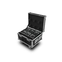
| Package contents | Nexus™ 4x4, Ø5 Allen key with handle, Neutrik® powerCON® power cord, reference manual, warranty card |
| Maintenance | Disconnect when not in use, allow to acclimate after temperature change, do not use outdoors |
| Factory reset | Disconnect, hold the < and > buttons, reconnect, confirm |
| Network compatibility | TCP/IP via Ethernet for Art-Net and Kling-Net |
| Display | Control panel with screen and navigation buttons |
Frequently Asked Questions - Nexus 4×4 Chauvet
User questions about Nexus 4×4 Chauvet
0 question about this device. Answer the ones you know or ask your own.
Ask a new question about this device
Download the instructions for your Professional lighting in PDF format for free! Find your manual Nexus 4×4 - Chauvet and take your electronic device back in hand. On this page are published all the documents necessary for the use of your device. Nexus 4×4 by Chauvet.
USER MANUAL Nexus 4×4 Chauvet
natural_image
Line drawing of a mechanical tray with circular indentations and a handle (no text or symbols)About this Guide
The Nexus™ 4x4 Quick Reference Guide (QRG) has basic product information such as connection, mounting, menu options, and DMX values. Download the User Manual from www.chauvetprofessional.com for more details.
Disclaimer
The information and specifications contained in this QRG are subject to change without notice.
Safety Notes
• DO NOT open this product. It contains no user-serviceable parts.
• DO NOT look at the light source when the product is on.
- To eliminate unnecessary wear and improve its lifespan, during periods of non-use completely disconnect the product from power via breaker or by unplugging it.
- CAUTION: When transferring product from extreme temperature environments, (e.g. cold truck to warm humid ballroom) condensation may form on the internal electronics of the product. To avoid causing a failure, allow product to fully acclimate to the surrounding environment before connecting it to power.
- CAUTION: This product's housing may be hot when lights are operating.
- Mount this product in a location with adequate ventilation, at least 20 in (50 cm) from adjacent surfaces.
- DO NOT leave any flammable material within 50 cm of this product while operating or connected to power.
• USE a safety cable when mounting this product overhead.
• DO NOT hang product using only the coffin locks.
• DO NOT operate this product outdoors or in any location where dust, excessive heat, water, or humidity may affect it.
- DO NOT operate this product if the housing, lenses, or cables appear damaged.
• DO NOT connect this product to a dimmer or rheostat.
• ONLY connect this product to a grounded and protected circuit.
• ONLY use the hanging/mounting bracket to carry this product.
• In the event of a serious operating problem, stop using immediately.
- The maximum ambient temperature is 104 °F (40 °C). Do not operate this product at higher temperatures.
Contact
Outside the U.S., United Kingdom, Ireland, Mexico, or Benelux, contact your distributor to request support or return a product. Visit www.chauvetprofessional.com for contact information.
What Is Included
- Nexus™ 4x4
- Neutrik® powerCON® power cord
• #5 Allen key with handle - Warranty card
- Quick Reference Guide
AC Power
This product has an auto-ranging power supply that can work with an input voltage range of 100–240 VAC, 50/60 Hz.

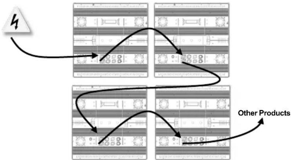
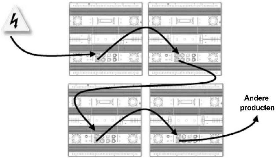
Power Linking
To eliminate unnecessary wear and improve its lifespan, during periods of non-use completely disconnect the product from power via breaker or by unplugging it.
The Nexus ^TM 4x4 supports power linking in the quantities listed below. Do not link more than:
• 4 products at 120 V,
• 7 products at 208 V, or
• 8 products at 230 V.
Power linking cords can be purchased separately.
Power Linking Diagram
flowchart
graph TD
    A["Product 1"] --> B["Processing Unit"]
    B --> C["Product 2"]
    C --> D["Processing Unit"]
    D --> E["Other Products"]
    E --> F["Product 3"]
    F --> G["Processing Unit"]
    G --> H["Other Products"]
AC Plug
| Connection | Wire (U.S.) | Wire (Europe) | Screw Color |
| AC Live | Black | Brown | Yellow/Brass |
| AC Neutral | White | Blue | Silver |
| AC Ground | Green/Yellow | Green/Yellow | Green |
Replacing the Fuse
- Disconnect the product from power.
- Using a flat-head screwdriver, unscrew the fuse holder cap from the housing.
- Remove blown fuse and replace with a good fuse of the same type and rating.
- Screw the fuse holder cap back in place.
- Reconnect the product to power.
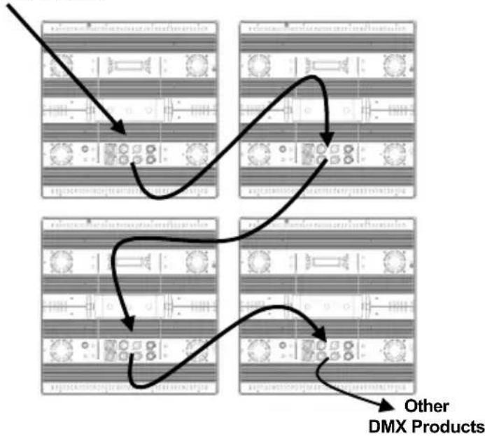
DMX Linking
The Nexus™ 4x4 works in Master/Slave mode or with a DMX controller using its DMX ports. A DMX Primer is available from www.chauvetprofessional.com.
DMX Linking Diagram
DMX Controller or Master
flowchart
graph TD
    A["Step 1: DMX Products"] --> B["Step 2: DMX Products"]
    B --> C["Step 3: DMX Products"]
    C --> D["Step 4: DMX Products"]
    D --> E["Other DMX Products"]
DMX Personalities
The Nexus™ 4x4 has 5 DMX personalities: 3-, 5-, 9-, 48-, and 53-channel. For more information, see the DMX Values in this QRG, or the User Manual on the Chauvet website at http://www.chauvetlighting.com/product-manuals-literature/.
Master/Slave Mode
The Nexus™ 4x4 works in Master/Slave mode. For more information, see the User Manual on the Chauvet website.
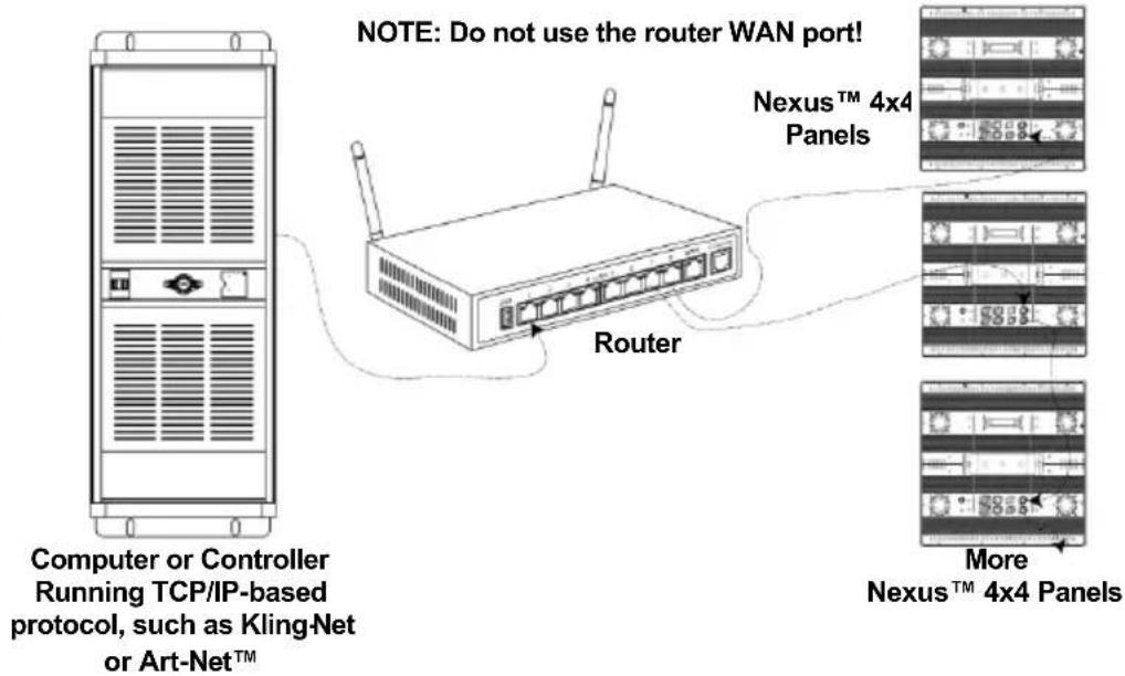
Ethernet Connections
Ethernet connections link Nexus™ 4x4 panels to routers and each other through their Neutrik® etherCON® ports. Ethernet connections are for running TCP/IP-based control system, such as Kling-Net and Art-Net™. All Neutrik® etherCON® ports can be either input or output ports, and panels can be linked to each other, but the start of each chain of panels must be a router port.
Ethernet Connections Diagram
Kling-Net Mode
Kling-Net is a network protocol that uses TCP/IP to send DMX over a network and into the Neutrik® etherCON® connection ports of the Nexus™ 4x4 panels. Kling- Net works seamlessly with Kling-Net-supported ArKaos software for configuring and mapping display devices. For more information, see the User Manual on the Chauvet website at http://www.chauvetlighting.com/product-manuals-literature/.
Art-Net™ Mode
Art-Net™ is an Ethernet protocol that uses TCP/IP to send DMX signals over a network and into the Neutrik® etherCON® connection ports of the Nexus™ 4x4 panels. Art-Net™ requires configuration through the control panel. For more information, see the Menu Map in this QRG or the User Manual on the Chauvet website at http://www.chauvetlighting.com/product-manuals-literature/.
An Art-Net™ Primer is available from www.chauvetprofessional.com. Art-Net™ is designed and copyrighted by Artistic Licence Holdings Ltd.

Reset To Factory Defaults
Nexus™ 4x4 panels do not work with Art-Net™ controllers sending in Broadcast mode. For information about the controller's mode, see the controller's User Manual.
- Disconnect the Nexus ^TM 4x4 from power.
- Press and hold
- Reconnect the Nexus ^TM 4x4 to power.
- Release
- Press
.
Kling-Net Mapper
Kling-Net Mapper is part of the ArKaos software package. It informs the ArKaos software about the layout of the Nexus ^TM 4x4 products in a process called mapping.
The following section provides step-by-step instructions for mapping the Nexus ^TM 4x4 products.
Part 1: Confirm Network Connectivity
- Connect the ArKaos computer and Nexus™ 4x4s to the same network. See Ethernet Connections Diagram.
- Set all the Nexus ^TM 4x4s to Kling-Net operating mode.
- Open the ArKaos Kling-Net Mapper. All the Kling-Net devices populate a list on the left side of the screen in the Connected Devices window.
The Connected Devices Window
It can take up to 20 seconds for all the products to populate the list and the color of the device's listing provides information about its status.
| Colors and Activity | Explanation |
| Black with an ID number and IP address | There is connectivity and everything is working properly, but the device is not yet mapped. |
| Green with an ID number and IP address | There is connectivity and everything is working properly, and the device is mapped. |
| Black to red with no IP address during initial population | The King-NetTM Mapper could not find an IP address for the device, most likely because the system is using an Ethernet switch instead of an Ethernet hub. |
| Black to red after initial population | The connectivity has been lost. |
Part 2: Test Network Connectivity
- Select the Output dropdown icon from the tool bar at the top of the Kling-Net Mapper screen. One of the options will be Test Pattern.
- Select Test Pattern. The image to the right of the icon is a small screen, indicating that Test Pattern is the current mode.
- Select the icon to the right of the Output dropdown icon. One of the options will be Flashing Output Selection.
- Select Flashing Output Selection. The icon is a faded green square with an arrow, indicating that a flashing green light is the current test pattern.
- Left click once on an LED display product. The product flashes green.
- Repeat Step 4 for every product in the list.
Part 3: Map The Products For ArKaos
- Make sure the Nexus™ Aw 4x4 products are all listed in the Connected Devices window and have flashed when tested. For more information, see Part 1: Confirm Network Connectivity.
- Click on the first product in the list and drag it onto the mapping image in the center of the screen. A shape representing the display product shows on the mapping image. The product displays the pattern on the mapping image.
- Drag, rotate, and resize the shape on the mapping image until it is in the position needed for the presentation layout.
- Repeat Steps 2 thru 3 for every Nexus™ Aw 4x4 product.
- Complete Parts 1 and 2.
- Click on File in the ArKaos Media Mapper.
- Click on Save As.
- Save the file.

Mounting
Remember the location of the file because the file must be loaded into the ArKaos software.
The Nexus ^TM 4x4 can be mounted in almost any orientation provided each individual product is secured through the mounting bracket. The coffin locks are for product alignment only and are not weight bearing. DO NOT hang product using only the coffin locks.
Product Mounting Diagram
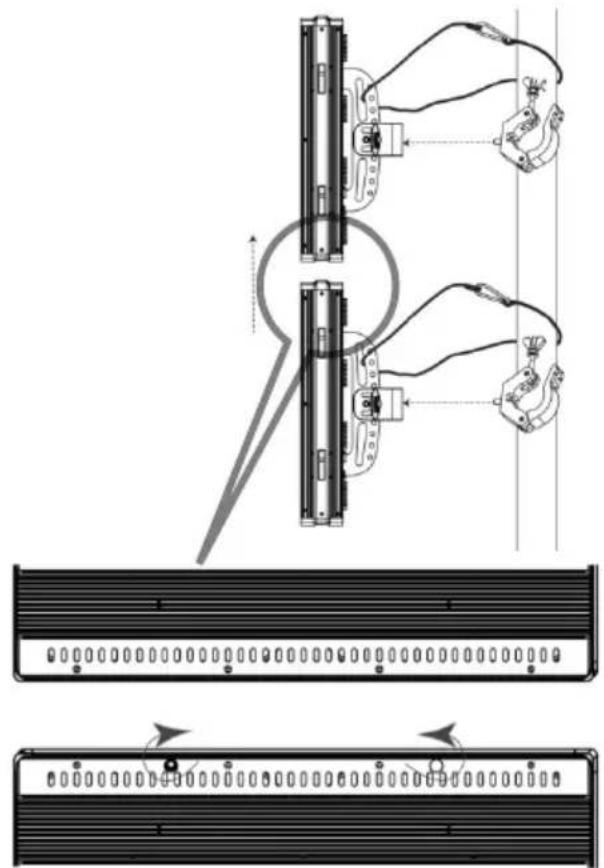
natural_image
Technical diagram showing mechanical assembly with two vertical components and a close-up of a rectangular panel (no text or symbols)Control Panel Description
| Button | Function |
| Scrolls through the main menu options or exits the current menu option. | |
| Enters into the highlighted menu option or sets the currently selected value. | |
| Navigates up through a list of menu options or values. | |
| Navigates down through a list of menu options or values. |
Home Screen
The home screen on the control panel display shows the current operating state as follows:
if the Nexus™ 4x4 is in Standalone or Master mode if the Nexus™ 4x4 is in Art-Net™, Kling-Net, or DMX mode
Exiting Auto Show And Static Modes
Auto Show and Static modes are not exited automatically when another mode is selected. To exit Auto Show or Static mode, do the following:
- Go to the Master/Slave main level.
- Select Slave.
- Press
. - Press

Setting changes are not activated until the control panel display returns to the home screen. To return the control panel display to the home screen press and hold
flowchart
graph TD
    A["Stage 1: Initial State"] --> B["Stage 2: Intermediate Stage"]
    B --> C["Stage 3: Final Product"]
    C --> D["Outros Productos"]
Enchufe CA
natural_image
Front view of a server rack unit with ventilation grilles and indicator lights (no text or symbols visible)natural_image
Diagram showing two mechanical assembly steps with wiring and a central component, no text or symbols present.natural_image
Front view of a server rack unit with ventilation grilles and indicator lights (no text or symbols visible)natural_image
Technical diagram showing mechanical assembly with two vertical components and a close-up of a server rack (no text or symbols present)Power Linking- diagram
flowchart
graph TD
    A["Stage 1"] --> B["Process Step 1"]
    B --> C["Process Step 2"]
    C --> D["Process Step 3"]
    D --> E["End"]
    style A fill:#f9f,stroke:#333
    style B fill:#ccf,stroke:#333
    style C fill:#cfc,stroke:#333
    style D fill:#fcc,stroke:#333
    style E fill:#ffc,stroke:#333