ÉPIX Strip IP 50 - Professional lighting Chauvet - Free user manual and instructions
Find the device manual for free ÉPIX Strip IP 50 Chauvet in PDF.

User questions about ÉPIX Strip IP 50 Chauvet
0 question about this device. Answer the ones you know or ask your own.
Ask a new question about this device
Download the instructions for your Professional lighting in PDF format for free! Find your manual ÉPIX Strip IP 50 - Chauvet and take your electronic device back in hand. On this page are published all the documents necessary for the use of your device. ÉPIX Strip IP 50 by Chauvet.
USER MANUAL ÉPIX Strip IP 50 Chauvet
natural_image
Technical line drawing of a long industrial air duct system with cooling fans and ventilation grilles (no text or symbols)About This Guide
The EPIX Strip IP 50 Quick Reference Guide (QRG) has basic product information such as connection and mounting. Download the ÉPIX Drive 2000 IP User Manual from www.chauvetprofessional.com for more details.
Disclaimer
The information and specifications contained in this QRG are subject to change without notice.
LIMITED WARRANTY
FOR WARRANTY REGISTRATION AND COMPLETE TERMS AND CONDITIONS PLEASE VISIT OUR WEBSITE. For Customers in the United States and Mexico: www.chauvetlighting.com/warranty-registration.
For Customers in the United Kingdom, Republic of Ireland, Belgium, the Netherlands, Luxembourg, France, and Germany: www.chauvetlighting.eu/warranty-registration.
Chauvet warrants that this product shall be free from defects in material and workmanship under normal use, for the period specified in, and subject to the exclusions and limitations set forth in the full limited warranty on our website. This warranty extends only to the original purchaser of the product and is not transferable. To exercise rights under this warranty, you must provide proof of purchase in the form of an original sales receipt from an authorized dealer that shows the product name and date of purchase. THERE ARE NO OTHER EXPRESS OR IMPLIED WARRANTIES. This warranty gives you specific legal rights. You may also have other rights that vary from state to state and country to country. This warranty is valid only in the United States, United Kingdom, Republic of Ireland, Belgium, the Netherlands, Luxembourg, France, Germany and Mexico. For warranty terms in other countries, please consult your local distributor.
Safety Notes
These Safety Notes include important information about installation, use, and maintenance.
- DO NOT open this product. It contains no user-serviceable parts.
- To eliminate unnecessary wear and improve its lifespan, during periods of non-use completely disconnect the product from power via breaker or by unplugging it.
- CAUTION: This product's housing may be hot when lights are operating.
- CAUTION: When transferring product from extreme temperature environments, (e.g. cold truck to warm humid ballroom) condensation may form on the internal electronics of the product. To avoid causing a failure, allow product to fully acclimate to the surrounding environment before connecting it to power.
- CAUTION: This product's housing may be hot when lights are operating.
• Mount this product in a location with adequate ventilation, at least 20 in (50 cm) from adjacent surfaces.
• DO NOT leave any flammable material within 50 cm of this product while operating or connected to power.
- USE a safety cable when mounting this product overhead.
- DO NOT submerge this product (IP65). Temporary outdoor operation is fine.
- When using this product in an outdoor environment, use IP65 (or higher) rated power and data cables. Be sure to secure unused power and data ports with attached IP65 covers.
- DO NOT operate this product if the housing, ports, or cables appear damaged.
- DO NOT connect this product to a dimmer or rheostat.
- ONLY connect this product to an ÉPIX Drive 2000 IP or ÉPIX Drive 900.
- Only use the hanging/mounting bracket to carry this product.
- In the event of a serious operating problem, stop using immediately.
• The maximum ambient temperature is 113 °F (45 °C). Do not operate this product at higher temperatures.
Contact
Outside the U.S., United Kingdom, Ireland, Benelux, France, Germany, or Mexico, contact your distributor to request support or return a product. Refer to Contact Us at the end of this QRG for contact information.
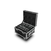
What is Included
- EPIX Strip IP 50
• Square Milky Filter (Installed) - Black Stealth Filter
- Round Milky Filter
- Quick Reference Guide
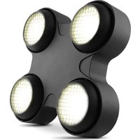
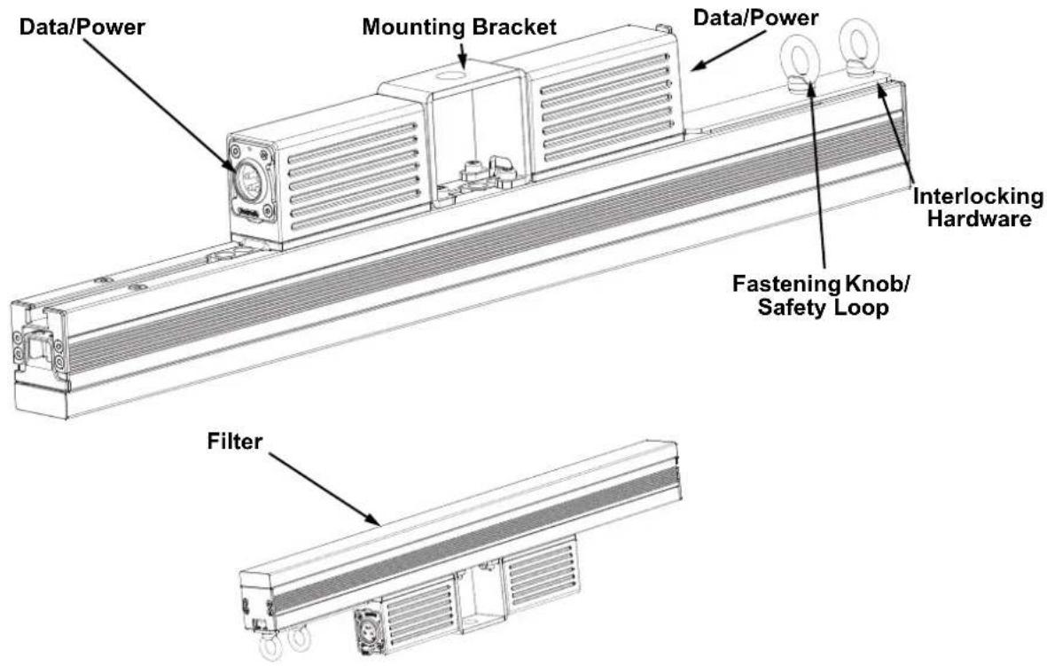
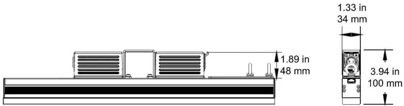
Product Overview
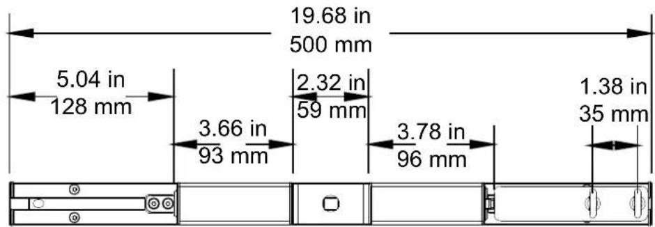
Product Dimensions
Power
This product is powered by an ÉPIX Drive 2000 IP or ÉPIX Drive 900. Refer to the ÉPIX Drive 2000 IP/900 User Manuals for detailed instructions on how to connect this product to power.
Power Linking
You can link up to 20 EPIX Strip IP 50 products to each port of an ÉPIX Drive 2000 IP. Never exceed this number.

• Use ONLY IP65 4-pin XLR cables with the EPIX Strip IP 50. For our CHAUVET Professional line of IP65 4-pin XLR cables, go to https://www.chauvetprofessional.com/accessories.
- To eliminate wear and improve its lifespan, during periods of non-use completely disconnect the ÉPIX Drive 2000 IP from power via breaker or by unplugging it.
Scrambled Pulse-Width Modulation
This product features Scrambled-PWM (S-PWM) technology, which de-synchronizes the pulse widths of each color of the multi-color LEDs. This ensures that there is always some LED output, reducing flicker, and maintaining the same grayscale performance.
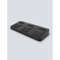
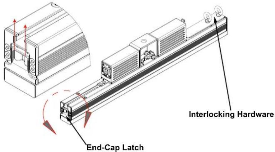
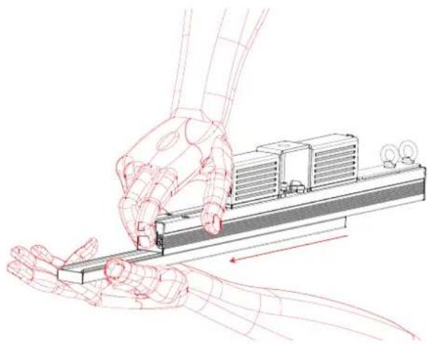
Filter Installation
The EPIX Strip IP 50 includes a Square Milky Filter already installed. Follow the procedure below to install the included Black Stealth Filter or Round Milky Filter.
- Locate the end cap of the product that does not have the interlocking hardware.
- Push in on the end-cap latch.
- Slide the installed filter out and replace it with the desired filter.
- Release the end-cap latch.
natural_image
Illustration of a robotic hand interacting with a mechanical device (no text or symbols visible)Mounting
Before mounting this product, read the Safety Notes. Use at least one mounting point per product. Make sure the mounting clamps are capable of supporting the weight of the product. For our CHAUVET Professional line of mounting clamps, go to http://trusst.com/products.
Mounting Diagram
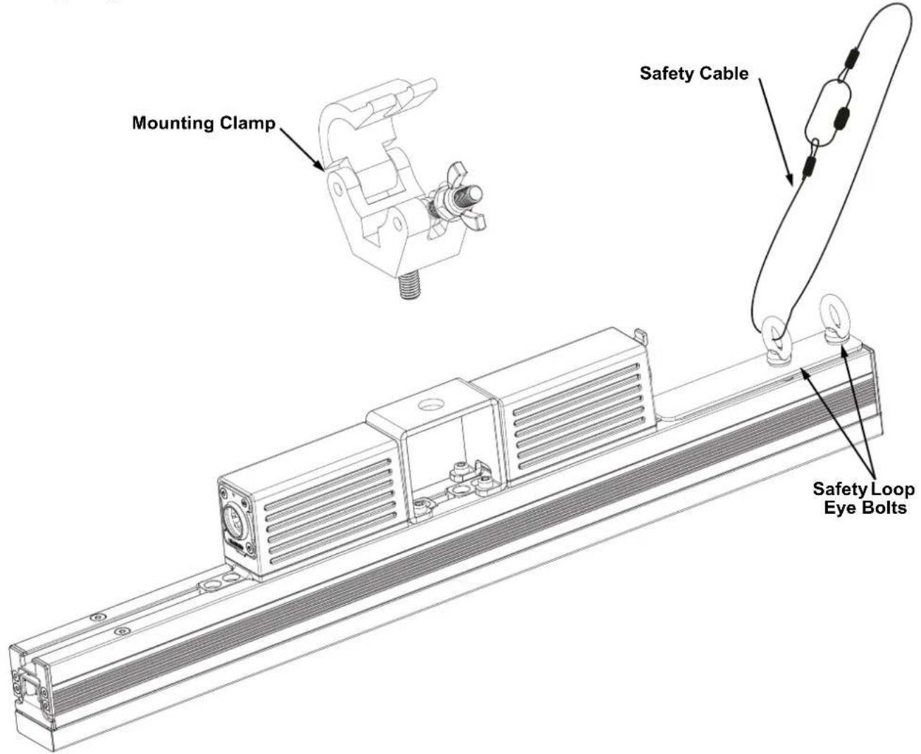
Vertical Mounting Instructions
- Attach the clamp to the mounting bracket.
- Attach the clamp to the desired structure or surface.
- Attach a safety cable to the product's safety loop.
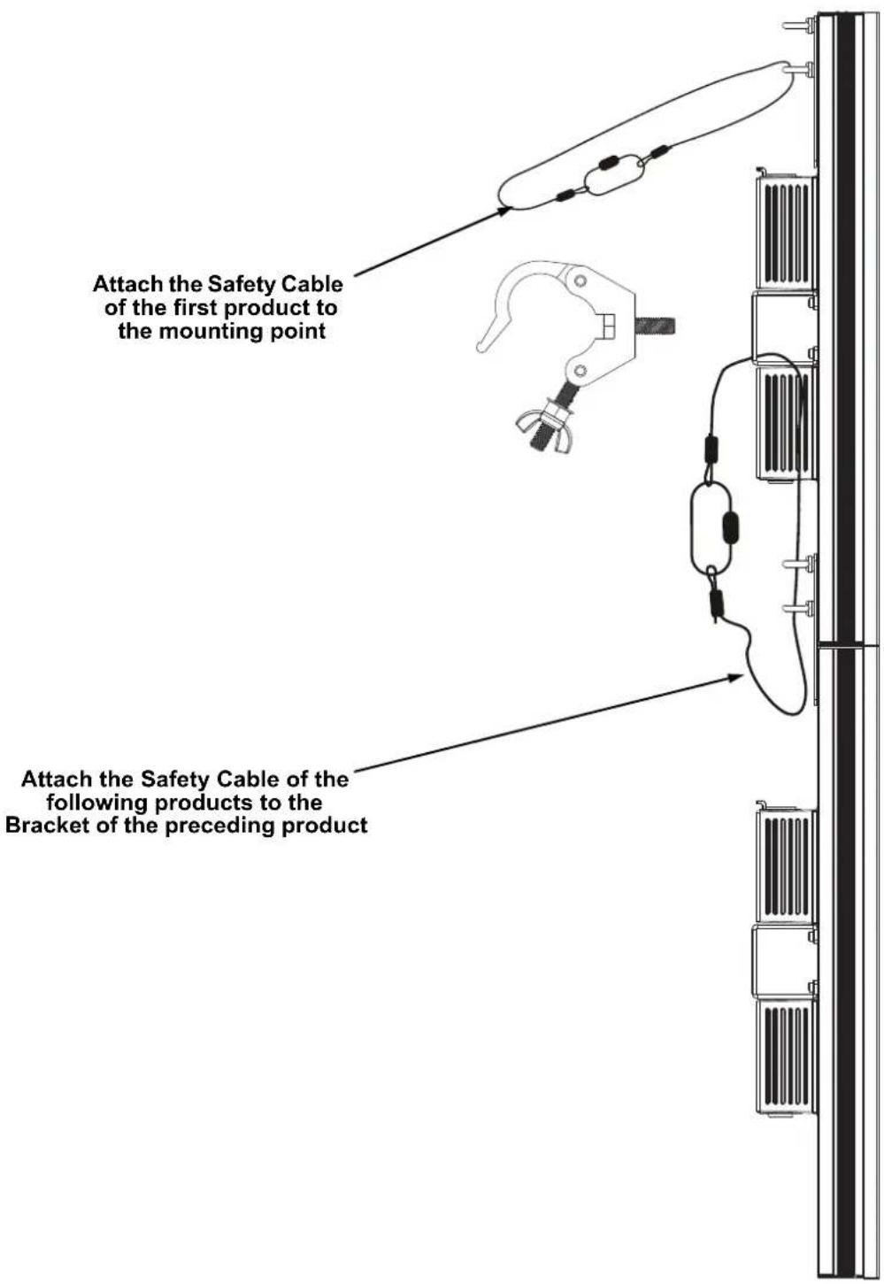

Never attach more than 6 products together when hanging vertically from a single mounting point.
Series Attachment Instructions
The EPIX Strip IP 50 can be attached in an end to end formation to create a strip up to 4 meters long from one mounting point. Do not connect any more than 6 EPIX Strip IP 50 products in a row when hanging vertically.
- Loosen the 2 fastening eye bolts.
- Slide the connecting bracket out until it stops and tighten the eye bolt closest to the center of the product.
- Slide the second EPIX Strip IP 50 into the connecting bracket and tighten the remaining eye bolt.
- Attach the safety cable as shown in Vertical Mounting Instructions.
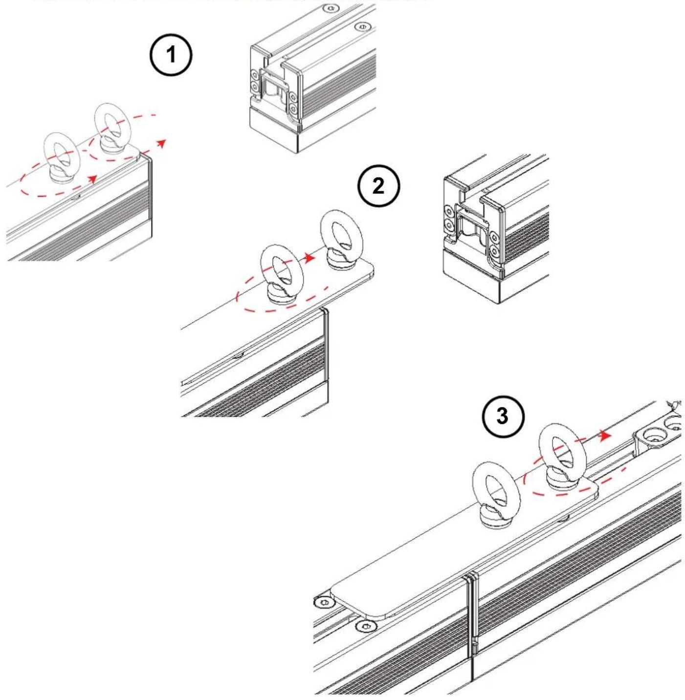

Install the safety cable last when attaching EPIX Strip IP 50 products in series.
Technical Specifications
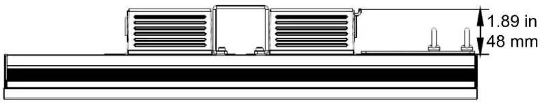
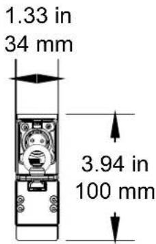
Dimensions and Weight
Filter Length Width Height Weight
| Square Milky Filter 19.68 in (500 mm) 1.33 in (34 mm) 3.93 in (100 mm) 3.4 lb (1.5 kg) |
| Black Stealth Filter 19.68 in (500 mm) 1.33 in (34 mm) 3.46 in (88 mm) 3.4 lb (1.5 kg) |
| Round Milky Filter 19.68 in (500 mm) 1.77 in (45 mm) 5.03 in (128 mm) 3.4 lb (1.5 kg) |
Note: Dimensions in inches are rounded.
Power
| Power Supply Range | Power Linking | ||
| ÉPIX Drive 2000 IP | 100 to 240 VAC, 50/60 Hz | 20 per ÉPIX Drive 2000 IP port | |
| Parameter | 120 V, 60 Hz | 208 V, 60 Hz | 230 V, 50 Hz |
| Consumption | 16 W | 17 W | 17 W |
| Operation Current | 0.133 A | 0.082 A | 0.073 A |
| Power I/O | U.S./Worldwide | UK/Europe | |
| Power Input Connector | IP65 4-pin XLR | IP65 4-pin XLR | |
| Power Cord Plug | IP65 4-pin XLR | IP65 4-pin XLR | |
Light Source
| Type | Color | Quantity | Lifespan |
| SMD 505 LED | Tri-color RGB | 50 | 50,000 hours |
Photometrics
| Parameter | Square Milky Filter | Black Stealth Filter | Round Milky Filter |
| Viewing Angle | 160° | 125° | 160° |
| Illuminance | 2,470 NITS | 1,455 NITS | 1,360 NITS |
| Pixel Pitch | 10 mm | 10 mm | 10 mm |
| Refresh Rate | 4,800 Hz | 4,800 Hz | 4,800 Hz |
Control
| Data I/O | Channel Range (Art-NetTM/sACN) | Channel Range (Kling-Net) |
| IP65 4-pin XLR | 7, 15, 30, 75, or 150 | Determined by ArKaos MediaMaster software |
Thermal
| Maximum External Temp. | Cooling |
| 113 °F (45 °C) | Convection |
Ordering
| Product Name | Item Name | Item Code | UPC Number |
| EPIX Strip IP 50 | EPIXSTRIPIP | 03091435 781462217839 |
Acerca de esta guía
natural_image
Illustration of a robotic hand interacting with a mechanical device (no text or symbols visible)Montaje

natural_image
Illustration of a robotic hand interacting with a mechanical device (no text or symbols visible)Montage

Stroom
natural_image
Illustration of a robotic arm interacting with a mechanical device (no text or symbols visible)Montage

General Information Technical Support
Chauvet World Headquarters
Address: 5200 NW 108th Ave. Voice: (844) 393-7575
Sunrise, FL 33351 Fax: (954) 756-8015
Voice: (954) 577-4455 Email: chauvetcs@chauvetlighting.com
Fax: (954) 929-5560
Toll Free: (800) 762-1084 Website: www.chauvetprofessional.com
Chauvet Europe Ltd.
Address: Unit 1C Email: UKtech@chauvetlighting.eu
Brookhill Road Industrial Estate
Pinxton, Nottingham, UK Website: www.chauvetprofessional.eu
NG16 6NT
Voice: +44 (0) 1773 511115
Fax: +44 (0) 1773 511110
Chauvet Europe BVBA
Address: Stokstraat 18 Email: BNLtech@chauvetlighting.eu
9770 Kruishoutem
Belgium Website: www.chauvetprofessional.eu
Voice: +32 9 388 93 97
Chauvet France
Address: 3, Rue Ampère
91380 Chilly-Mazarin
Email: FRtech@chauvetlighting.fr
France Website: www.chauvetprofessional.eu
Voice: +33 1 78 85 33 59
Chauvet Germany
(Entrance by Calle 2)
Email: servicio@chauvet.com.mx
Zona Industrial Lerma Website: www.chauvetprofessional.mx
Visit the applicable website above to verify our contact information and instructions to request support. Outside the U.S., United Kingdom, Ireland, Mexico, France, Germany, or Benelux, contact the dealer of record.

UL 1573
CSA C22.2 No. 166
E113093


RoHS