IDROSALLY - Central heating boiler EDILKAMIN - Free user manual and instructions
Find the device manual for free IDROSALLY EDILKAMIN in PDF.


| Product type | Central heating pellet boiler |
| Brand | Edilkamin |
| Model | IDROSALLY |
| Fuel | Wood pellets, diameter 6 mm |
| Rated useful thermal power | 14 kW |
| Reduced useful thermal power | 3.9 kW |
| Power transmitted to water (rated) | 11 kW |
| Rated efficiency | 91.6 % |
| Reduced efficiency | 97.6 % |
| Hopper capacity | 25 kg |
| Autonomy | 7 to 28 hours |
| Weight (ceramic version, with packaging) | 257 kg |
| Weight (steel version, with packaging) | 247 kg |
| Power supply | 230 Vac +/- 10%, 50 Hz |
| Average power consumption | 120 W |
| Power consumption at ignition | 400 W |
| Flue gas duct diameter | 80 mm |
| External air intake diameter | 40 mm |
| Maximum water service pressure | 1.5 bar |
| Water content | 12 liters |
| Indicative heated volume | 365 m³ |
| Maximum water service temperature | 90 °C |
| Remote control frequency | 2.4 GHz |
| France certification | Flamme Verte |
Frequently Asked Questions - IDROSALLY EDILKAMIN
User questions about IDROSALLY EDILKAMIN
0 question about this device. Answer the ones you know or ask your own.
Ask a new question about this device
Download the instructions for your Central heating boiler in PDF format for free! Find your manual IDROSALLY - EDILKAMIN and take your electronic device back in hand. On this page are published all the documents necessary for the use of your device. IDROSALLY by EDILKAMIN.
USER MANUAL IDROSALLY EDILKAMIN
Termostufa a pellet - Pellet Boiler-stove
natural_image
Exterior view of a black and white electric stove with visible flame inside (no text or symbols)UK Installation, use and maintenance
F Installation, usage et maintenance
natural_image
Close-up of a mechanical component with wires and connectors, no visible text or symbolsnatural_image
3D cutaway view of a red and gray electronic device showing internal components and ventilation (no text or symbols)natural_image
3D diagram of a device casing with internal components and labeled parts (no text or symbols beyond labels)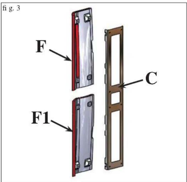
1) VERSIONE CON FIANCHI E TOP IN CERAMICA
Fig. 1
natural_image
3D rendered model of a curved mechanical part with red and black sections, marked with 'H' and two small bolts (no text or symbols on the object itself)natural_image
Illustration of a modern electric heater with red and silver casing (no text or symbols)2) VERSIONE CON FIANCHI IN ACCIAIO E PROFILI E TOP IN CERAMICA
Fig. 10
natural_image
Illustration of a red electric heater with its hood open, showing airflow and ventilation slots (no text or symbols)fig. 2
natural_image
3D cutaway view of a red and gray electronic device showing internal components and ventilation (no text or symbols visible)Attenzione:
natural_image
Close-up of a black handheld electronic device with a digital display showing '25x' and control buttons (no readable text beyond symbols)
natural_image
Circular red indicator dial with green ring and white outer ring, no visible text or symbolsnatural_image
3D cutaway view of a red and gray electronic device showing internal components and ventilation (no text or symbols)fig.B
MANUTENZIONE
natural_image
3D mechanical component inside a vehicle or enclosure, showing a black housing and red vertical panel (no text or symbols visible)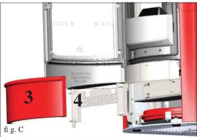
CONSIGLI PER POSSIBILI INCONVENIENTI
natural_image
Black and white photo of a vacuum cleaner with attached hose and control panel (no visible text or symbols)Bidone aspiracenere
The undersigned EDILKAMIN S.p.a. with head offi ce headquarters at Via Vincenzo Monti 47 - 20123 Milan - Italy - VAT IT00192220192
Declares under its own responsibility as follows: The pellet Boiler-stoves illustrated below conforms to Regulation EU 305/2011 (CPR) and to the harmonised European Standard EN 14785:2006
WOOD PELLET BOILER-STOVES, trademark EDILKAMIN, called IDROSALLY
Year of manufacture: Ref. Data nameplate Declaration of performance (DoP - EK n° 117): Ref. data tag plate
In addition, it is hereby declared that: The wood pellet Boiler-stoves IDROSALLYis in compliance with the requirements of the European directives: 2006/95/EC - Low voltage directive 2004/108/EC - Electromagnetic compatibility directive
EDILKAMIN S.p.a. will decline all responsibility of malfunctioning or damage to the equipment in case of unauthorized substitution, assembly or modifications of any sort on the said equipment on the part of non-EDILKAMIN personnel.
Dear Sir/Madam
Congratulations and thank you for choosing our product.
Please read this document carefully before you use this product in order to obtain the best performance in complete safety.
For further details or assistance, please contact the DEALER where you purchased the product or visit our website www.edilkamin.com. and click on DEALERS.
NOTE
- After having unpacked the boiler-stove, ensure that its contents are complete and intact (overing, remote control, small silicon tube, clamp, “cold-hand” handle to open the inner door, guarantee booklet, glove, CD/technical data sheet, spatula, dehumidifying salt).
n case of anomalies please contact the dealer where you purchased the product immediately.
You will need to present a copy of the warranty booklet and valid proof of purchase.
- Commissioning/ testing
This must be carried out by an EDILKAMIN authorised Technical Assistance Centre (TAC) to guarantee proper operation.
Commissioning, as specified in standard UNI 10683 consists in a series inspections to be performed with the boiler-stove installed in order to ascertain the correct operation of the system and its compliance to applicable regulations.
- Incorrect installation, incorrect maintenance, or improper use of the product, shall relieve the manufacturer from any damage resulting from the use of this product.
- the proof of purchase tag, necessary for identifying the boiler-stove, is located:
-on the top of the package
- in the warranty booklet found inside the fi rebox
- on the ID plate affixed to the back side of the unit;
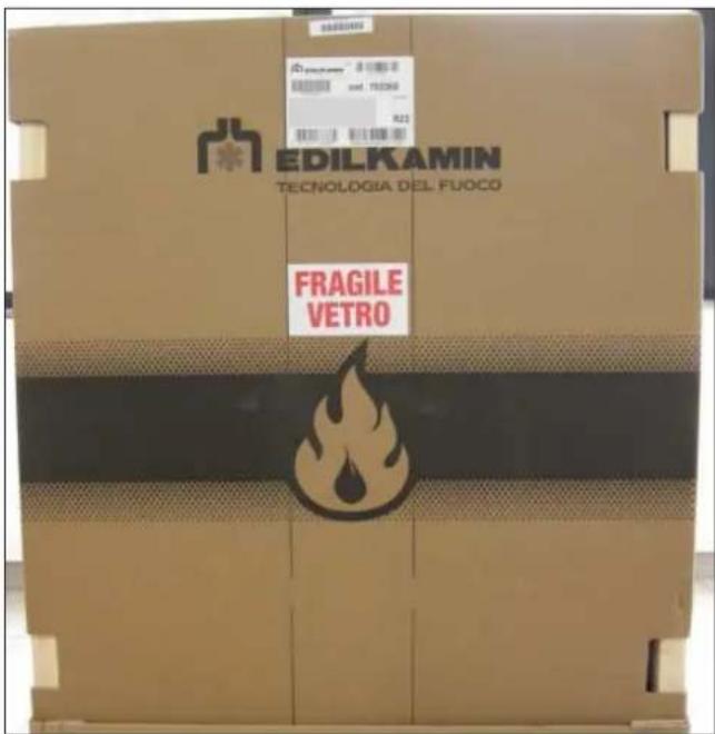
This documentation must be saved for identification together with the valid proof of purchase receipt. The data contained therein must be reported when requesting information and made available should servicing be required;
- All images are for illustration purposes only; actual products may vary.
SAFETY INFORMATION
THE BOILER-STOVE MUST NEVER BE MADE TO OPERATE WITHOUT WATER IN THE SYSTEM.
IT CAN BE DAMAGED IF IT IS IGNITED WITH NO WATER IN THE SYSTEM.
MUST BE MADE WITH A PRESSURE OF ABOUT 1.5 BAR.
- The appliance is not designed to be used by people, including children, with reduced physical, sensorial or mental abilities. Children must be supervised to ensure they do not play with the appliance.
- The main risks that may derive from using the boiler-stove pertain to non-compliance with installation instructions, direct contact with live electrical parts (internal), contact with the fire or hot parts (glass, pipes, hot air output), when extraneous substances or non-recommended fuel are introduced, or due to incorrect maintenance or by repeatedly pressing the ignition button without having emptied the crucible.
- Should components fail, the boiler-stove is equipped with safety devices to guarantee its automatic shutdown. These are activated without any intervention required.
- In order to function correctly, the boiler must be installed in accordance with the instructions given herein and the door must not be opened during operation: combustion is fully automatic and requires no intervention.
- Only use certified, high quality, 6 mm diameter wooden pellets for fuel.
- Under no circumstances should any foreign substances be put into the hearth or the hopper. NEVER use liquid fuel to ignite the boiler-stove or rekindle the embers.
- Do not use fl ammable products to clean the smoke channel (the flue section connecting the boiler-stove smoke outlet to the chimney fl ue).
- Do not clean when hot.
- Hearth and hopper components must only be cleaned with a vacuum cleaner.
-
The glass can be cleaned when COLD with a suitable product and a cloth.
-
The boiler-stove must not function if the door is open, if the glass is broken or if the pellet-loading port is open.
- It must not be used as a step ladder or a base on which to rest any object.
- Do not place anything, which is not heat resistant near the boiler-stove.
- Do not lay laundry directly on the boiler-stove to dry. Any clothes horse or similar must be placed at a safe distance from the boiler-stove (danger of fire).
- Make sure the boiler-stove is installed and ignited the first time by Edilkamin-qualified CAT personnel (technical assistance centre) in accordance with the instructions provided here within; this is an essential requirement for the validation of the guarantee.
- Whilst the boiler-stove is in operation, the exhaust pipes and door become very hot (do not touch without using the right gloves).
- Do not obstruct the ventilation apertures in the room where the boiler-stove is installed, nor the air inlets of the boiler-stove itself.
- Do not wet the boiler-stove and do not go near electrical parts with wet hands.
- Do not use reducers on the smoke exhaust pipes.
- The boiler-stove must be installed in a room that is suitable for fire prevention and equipped with all that is required (power and air supply and outlets) for the boiler-stove to function correctly and safely.
- The boiler-stove must be kept in a room where the temperature is above 0^ .
- Use appropriate anti-freeze additives for the water of the system.
- In the event that the water used for filling and topping up has a hardness greater than 35^ , use a water softener. For suggestions please refer to regulation UNI 8065-1989 (Water Treatment In Heating Systems For Civil Use).
- SHOULD IGNITION FAIL, DO NOT RE-IGNITE UNTIL YOU HAVE EMPTIED THE COMBUSTION CHAMBER.
GENERAL INFORMATION
The boiler-stove is fuelled by pellets. These are little, cylindrical shapes of pressed wood whose combustion is controlled electronically.
The thermo-stove is able to heat water to feed the heating system (radiators, heated towel rails, and underfloor heating panels), as well as producing hot air with a fan to heat the room in which it is installed.
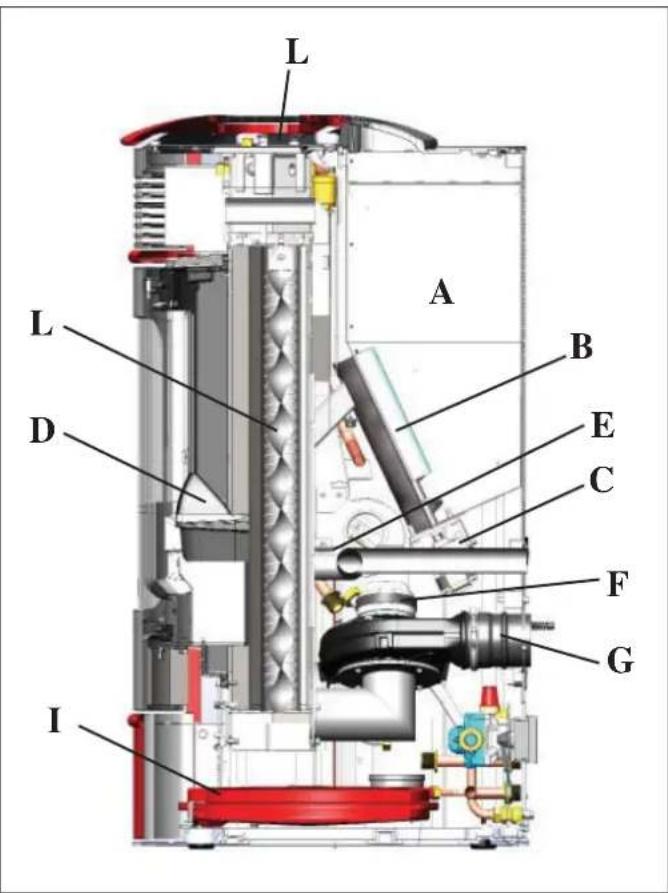
The fuel tank (A) is located at the rear of the boiler-stove. Filling the tank is through the back of the lid at the rear of the top. The fuel (pellets) is taken from the storage tank (A) and, via an Archimedes' screw (B) activated by a gear motor (C) it is then transported to the combustion crucible (D).
The ignition of the pellet is via air heated by an electrical heating element (E) and is sucked into the crucible by a smoke extractor (F).
The combustion air is drawn into the room (where there must be an air intake) smoke extractor (F).
The smoke produced by combustion, is extracted from the boiler-stove through the smoke extractor (F), and expelled from the pipe union (G) located in the bottom portion of the rear of the boilerstove.
The ash falls under and beside the crucible in which is housed an ash tray from which the ash must be periodically removed by vacuuming when cool.
The hot water produced by the boiler-stove is transferred via a circulator built into the boiler-stove itself, to the heating system circuit.
The boiler-stove is designed to function with closed expansion tank (I) and pressure valve, both of which are built in.
Fuel quantity, smoke extraction/combustion air supply and pump activation are regulated by the control board which is equipped with Leonardo software to achieve high combustion efficiency and low emissions.
The main functioning phases are managed by remote control, and there is also a simplified on/off key (page 48).
The exchanger tubes are cleaned by means of tube-cleaners (H) manoeuvred with a handle (L).
Aserial port is found at the back of the boiler-stove (optional cable: code 640560) to be connected to devices that allow remote ignition (e.g. remote telephone, local thermostat).
Operating modes
(for further details, please see page 50)
The temperature of the water required in the system is set via the panel (standard recommendation 70^ C) and the boiler manually or automatically modulates the power to maintain or reach this temperature.
The Eco function can be enabled in small systems (the boiler shuts down and goes on again according to the water temperature required).
GENERAL INFORMATION
• ELECTRONIC CIRCUIT BOARD
LEONARDO is a combustion safety and control system which allows optimal performance in all conditions thanks to two sensors measuring the pressure level in the combustion chamber and smoke temperature. The detection of and subsequent optimisation of these two parameters is continuous in order to correct operation anomalies in real time.
The LEONARDO system offers constant combustion, automatically regulating the draft based on the characteristics of the chimney flue (bends, length, shape, diameter, etc..) and environmental conditions (wind, humidity, atmospheric pressure, installations at high altitude, etc.). The standards for installation must be respected. LEONARDO system is also able to recognise the type of pellets and automatically djust the flow moment by moment to ensure the required level of combustion.

* patented
• ELECTRONIC CIRCUIT BOARD
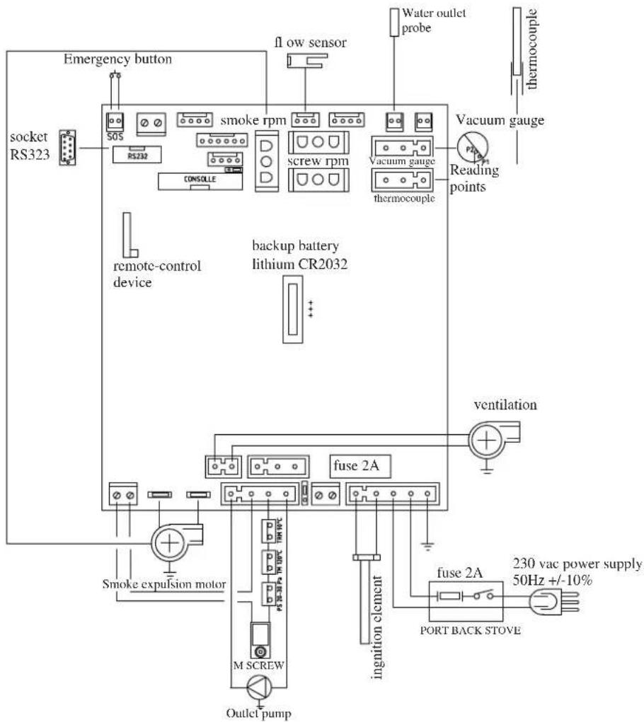
SERIAL PORT
The Dealer can install an optional on the AUX outlet for controlling the process of switching on and off (e.g. telephone remote, local thermostat), located at the rear oh the boiler-stove. Can be connected via special optional trestle (code 640560).
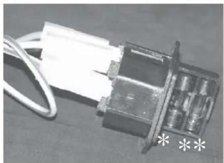
FUSE two fuses are inserted in the socket with switch, located on the back of the boiler-stove, one of which operational (*) and the other is held in reserve (* *).
BACKUP BATTERY
A backup battery is found on the control board (3-Volt CR 2032 battery). Its malfunction is indicated with the following messages (not considered a defect but due to normal wear-and-tear): "Battery check". For more detailed information, please contact the DEALER who has performed the first 1st ignition.
natural_image
Close-up of a mechanical component with wires and a metallic housing, marked with asterisks (no readable text or symbols)GENERAL INFORMATION
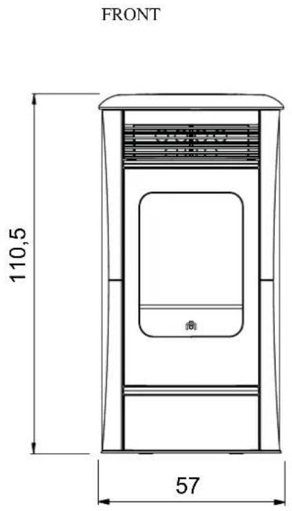
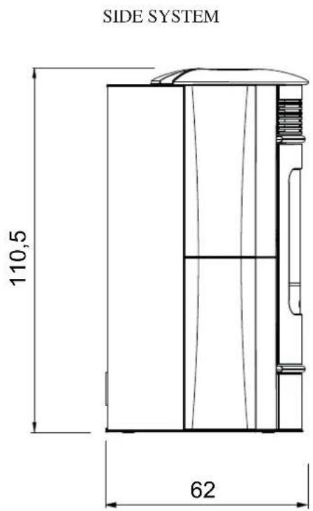
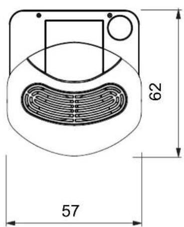
THE IDROSALLYIS PRODUCED IN SIX DIFFERENT FINISHES:
- dark grey steel with cream white ceramic inserts and top
- dark grey steel with red ceramic inserts and top
- dark grey steel with grey ceramic inserts and top
- cream white ceramic
- red ceramic
- parchment ceramic

GENERAL INFORMATION
| THERMO TECHNICAL CHARACTERISTICS according to EN 14785 (for other values, see DoP on page 40) | |||
| Nominal power Reduced power | |||
| Thermal power output 14 3,9 kW | |||
| Thermal power transferred to the water without fan | 11 2,5 kW | ||
| Thermal power transferred to the environment | 3 | 1,4 kW | |
| Yield / Efficiency | 91,6 | 97,6 | % |
| Emissions CO 13% O_2 | 0,010 | 0,025 | % |
| Fume temperature | 129 56 °C | ||
| Fuel consumption | 3,2 0,8 | kg/h | |
| Draught | 12 - 5 | 10 - 3 | Pa |
| Hopper capacity | 25 | kg | |
| Water content | 12 | Litres | |
| Maximum operating pressure of the water | 1,5 | bar | |
| Maximum operating temperature of the water | 90 | °C | |
| Autonomy | 7 | 28 | hours |
| Heatable volume * | 365 | m^3 | |
| Smoke outlet pipe diameter (male) | 80 | mm | |
| Air intake pipe diameter (male) | 40 | mm | |
| Weight including packaging (ceramic/steel) | 257/247 | kg | |
| TECHNICAL DATA FOR SIZING THE FLUE which must, in any case, comply with the guidelines of this sheet and the installation rules for each product | |||
| Nominal power Reduced power | |||
| Thermal power output 14 3,9 kW | |||
| Temperature of fumes on exit from the discharge pipe 155 67 °C | |||
| Minimum draught 0 - 5 Pa | |||
| Fume flow capacity | 10,6 | 3,6 | g/s |
* The heatable room dimensions are calculated on the basis of home insulation in compliance with Italian law 10/91, and subsequent changes together with an expected heat output of 33Kcal / m^3 per hour.
| ELECTRICAL CHARACTERISTICS | |
| Power supply 230Vac +/- 10% 50 Hz | |
| Average power consumption 120 W | |
| Power consumption during ignition 400 W | |
| Remote control frequency | Radio waves 2,4 GHz |
| Protection on electronic circuit board T2A, 250 Vac, 5x20 Fuse | |
N.B.
1) keep in mind that external devices can cause interference to the operation of the circuit board.
2) warning: activity on live components, maintenance and/or checks must be carried out by qualified personnel.
(before carrying out any maintenance, disconnect the appliance from the mains electricity)
3) In case of problems with the electrical grid, consult an electrician to evaluate the installation of a sine-wave UPS of at least 800 Va. Power variations greater than 10% can cause problems for the product.
The above data are indicative and are those resulting during certification on the part of the notified body. EDILKAMIN s.p.a. reserves the right to change the products at its discretion without notice.
GENERAL INFORMATION
• COMPONENTS - SAFETY AND DETECTION DEVICES
Smoke thermocouple
on the smoke outlet. It reads the smoke temperature. It regulates the ignition stage and shuts the boiler-fireplace down if the temperature is too high or too low.
Flow sensor
located in the extraction duct, is activated and shuts down the thermo stove when the flow of combustion air is incorrect, which means a resulting risk of low pressure problems in the smoke circuit.
Feed Screw safety thermostat
Placed near the pellet hopper. It disconnects the electrical supply to the gear motor if the temperature detected is too high.
Water temperature detector
It reads the water temperature in the boiler and sends the circuit board information for pump management and boiler power modulation.
If the temperature is too high, it starts a shutdown.
Water overheating safety thermostat
detects the water temperature in the thermo-stoves. If this is too high, it triggers the shutdown process by disconnecting the electrical supply to the gear motor.
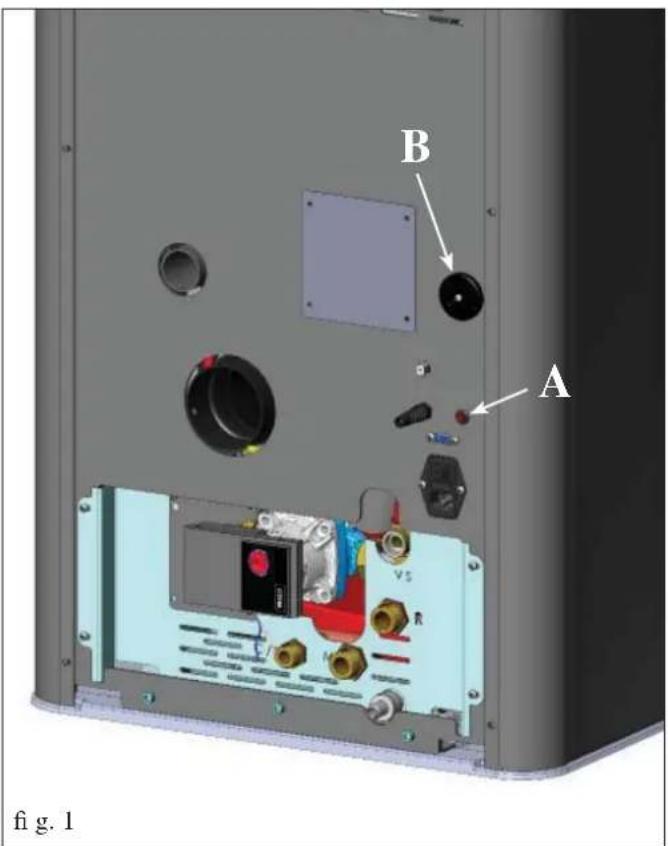
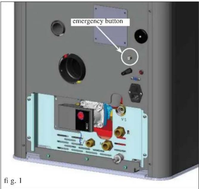
If the thermostat has been activated, it must be reset by pushing the red emergency button located on the back of the thermo stove (A -fi g. 1).
Overpressure valve 3 bar
Upon reaching the pressure stipulated on the plate, the system is triggered to discharge the water and consequently the water must be topped up.
WARNING!!!! remember to carry out the connection with the sewage system.
Electric coil
It sets off of the combustion of the pellets and it remains lit until the flame has been ignited. This component is subject to wear.
Smoke extractor
"Pushes" the smoke into the fl ue and draws out combustion air via a vacuum.
Vacuum gauge (electronic pressure sensor):
positioned on the smoke extractor, which detects the vacuum value (compared to the installation environment) in the combustion chamber.
Tank safety thermostat:
Located on the system that loads the pellets from the hopper. Trips when the temperature inside the boiler-stove is too high. It stops pellet loading, causing the boiler-stove to go out.
Pump (electronic circulator - see page. 53)
"Pushes" water toward the heating system.
Closed expansion tank
“absorbs” the variations in the volume of water contained inside the boiler-stove due to the heating effect.
Aheating technician must evaluate the need to add a second tank to the existing one, depending on total amount of water in the system.
Manometer
It is located on the right side of the thermo stove (B -fig. 2), and is used to read the water pressure.
When the thermo stove is running, the recommended pressure is 1.5 bar.
Drain tap
positioned on the back of the thermo stove, low down. It must be opened if the water the unit contains needs to be drained.
Venting valve:
positioned in the upper part (see page 43-49), it allows for the "bleeding" of any air present during the loading of water inside the boiler-stove.
N.B.:
IF THE BOILER-STOVE BLOCKS, THE REASON WILL APPEAR ON THE DISPLAY AND THIS WILL BE SAVED.
GENERAL INFORMATION

EDILKAMIN
TECNOLOGIA DEL FUOCO
EdRamin S.p.A.
20020 Lainale (MI) - Via Mascagni. 7
Tel. =39 02 93762
Fax:39 02 93762 400388
mail@edikamn.com
www.stalkamai.com
Capitale € 4.100.000 int. vers.
Sede begain
Declaration of performance
According to Regulation (EU) No. 305/2011
N. EK117
-
Unique identification code of the product-type BUOUX
-
Models [Article 11-4] IDROSALLY
-
Intended uses of the product in accordance with the applicable harmonized technical specification Appliance for domestic heating, fuelled with wood pellet, with hot water production
-
Name or trade mark of the manufacturer (Article 11-5) EDILKAMIN S.p.A. Via Mascagni, 7 - 20020 Lainate (MI) Italy
-
Name and address of the agent (Article 12-2)
-
Assessment and verification system for constancy of performance (Annex 5) System 3 and System 4
-
Laboratory notified ACTECO Srl - NB1880 Test report number (based on System 3) 1880-CPR-001/003-13
-
Declared performance
| Harmonized technical specification EN 14785:2006 | ||
| Essential characteristics Performance | ||
| Reaction to fire A1 | ||
| Distance to combustible materials(minimum distance in mm) | Rear = 300Sides = 150Front = 800Ceiling = NPDO Floor = NPD | |
| Risk of burning fuel falling out Pass | ||
| Emission of combustion productsCO (ref. at 13% O_2 )NOx (ref. at 13% O_2 )OGC (ref. at 13% O_2 )Particulate matter (ref. at 13% O_2 ) | Rated fuel load196 mg/ Nm^3 - 0,016%149 mg/ Nm^3 1 mg/ Nm^3 19 mg/ Nm^3 | Reduced fuel load313 mg/ Nm^3 - 0,025%117 mg/ Nm^3 2 mg/ Nm^3 48.9 mg/ Nm^3 |
| Surface temperature Pass | ||
| Electrical safety Pass | ||
| Cleanability Pass | ||
| Maximum operating pressure 1.5 bar | ||
| Mechanical resistance (to carry a chimney/flue) | NPD (No performance declared) | |
| Thermal outputNominal heat outputNominal space heating outputNominal boiler output (to water) | Rated fuel load14 kW3 kW11 kW | Reduced fuel load3.9 kW1.4 kW2.5 kW |
| Energy efficiency 91.9 % 97.5 % | ||
| Flue gas temperature [136°C] T[56°C] | ||
- The performance of the product identified in points 1 and 2 is in conformity with the declared performance in point 8
This declaration of performance is issued under the sole responsibility of the manufacturer identified in point 4. Signed for and on behalf of Edilkamin S.p.A. by:
Chief Executive officer
Lainate, 02/10/2014
Dott. Stefano BORSATTI
• CERTIFICATIONS AND BENEFITS \*
* Given their variability over time in the various countries, check from time to time.
This text is valid for the year this sheet was prepared (see edition details on the last page).
ITALY: allowed in Lombardy pursuant to DGR No. 1118-2013 allowed in the Marche region pursuant to Regional Law No. 3 of 2012 admitted to the Conto Termico (renewable heating incentive) with thermal coefficient 1, see the website www.edilkamin.com for how much you can save in the various areas admitted to a 50% deduction; 65% (check the conditions of external accessibility to the product)
FRANCE: enrolled in Flamme Verte
GERMANY: omplies with Bimsch
SWITZERLAND: complies with VKF
SLOVENIA: admitted to Bechia Ekosklad
CZECH REPUBLIC: admitted to NEW GREEN SAVE PROGRAMME and in accordance with the Directives of the Ministry of the Environment No. 9-2013
INSTALLATION
GENERAL NOTES
The smoke discharge and plumbing connections must be carried out by qualified personnel who can issue an installation declaration of conformity complying with national law.
In Italy it is necessary to refer to the standard declaration of conformity conforming to Ministerial Decree 37/2008 (pursuant to Law 46/1990) and standards UNI 10683 and UNI 10412-2/2009.
In the case of installation in a multiple-tenancy building, contact the building manager before installation.
VERIFY COMPATIBILITY WITH OTHER DEVICES
In Italy the boiler-stove MUST NOT be installed in the same space as type B gas heating equipment (e.g. gas boilers, stoves, and equipment served by an extraction hood - ref. UNI 10683 and 7129).
In general, the stove could create low pressure in the room, affecting the operation of such appliances or being affected by them.
VERIFY THE POWER SUPPLY
CONNECTION (the plug must be accessible)
The boiler-stove is supplied with a power cable that is to be connected to a 230V 50 Hz socket, preferably fitted with a magnetothermic switch.
The electrical system must comply with the law; particularly verify the efficiency of the earthing system.
The power line must have a suitable cross-section for the boiler power.
An inadequate earthing system can cause anomalies for which Edilkamin cannot be held liable.
In case of problems with the electrical grid, consult an electrician to evaluate the installation of a sine-wave UPS of at least 800 Va.
Power variations greater than 10% can cause problems for the product.
AIR INLET (to be mandatorily implemented)
The room where the boiler-stove is located must have an air intake with cross section of at least 80cm^2 to ensure replenishment of the air consumed by combustion.
Alternatively, the boiler-stove air may be taken directly from outside through a 4 cm steel extension of the pipe. In this case, there may be condensation problems and it is necessary to protect the air intake with a grille, which must have a free-section of at least 12 cm². The pipe must be less than 1 metre long and have no bends. It must end with section at 90° facing downwards or be fitted with a wind guard. In any case all the way air intake duct must be a free section of at least 12 cm².
The external terminal of the air inlet channel must be protected with an anti-insect netting that does not reduce the 12 cm^2 through passage.
POSITIONING AND DISTANCES FOR FIRE SAFETY
For correct operation the boiler-stove must be level.
Check the load-bearing capacity of the floor.
The boiler-stove must be installed in compliance with the following safety conditions:
- fl immability items must be kept at a minimum distance of 10 cm from the sides and back of the boiler-stove
- highly fl ammable items must be kept at a minimum distance of 80 cm if placed in front of the boiler-stove
- if the boiler-stove is installed on a flammable floor, a sheet of heat insulating material must be placed between the boiler-stove and the floor, which protrudes by at least 20 cm at the sides and 40 cm at the front.
Flammable objects must not be placed above the boiler-stove or at a distance that is any less than the stipulated safety distances. If connected to wooden walls or other flammable materials, the smoke exhaust pipe must be appropriately insulated with ceramic fi bre or other similar material.
INSTALLATION
SMOKE OUTLET
The boiler-stove must have its own smoke outlet (the smoke cannot be discharged into a smoke fl ue used by other devices).
The smoke is discharged through the 8 cm diameter outlet at the back of the boiler
A T-junction must be set up with a condensation collection stopper at the beginning of the vertical section.
The smoke outlet must be connected to outside by means of suitable steel pipes EN 1856 certifi ed.
All piping must be hermetically sealed and, if necessary, insulated.
To seal the various elements of the piping together, materials resistant to high temperatures must be used (silicon or mastics for high temperatures).
The pipe must be hermetically sealed.
The material used to seal and if necessary insulate the pipes, must be resistant to high temperatures (high temperature silicone or mastic).
The only horizontal section allowed may be up to 2 m long. It may have up to three 90° bends.
If the outlet is not fitted into a chimney flue, a vertical section and a wind guard are required (reference UNI 10683).
The vertical duct can be internal or external.
If the smoke channel (part of the pipe that goes from the boiler-stove to the chimney flue) is outside, it must be appropriately insulated. If the smoke channel is fitted inside a chimney flue, the latter must be suitable for solid fuel.
If it is wider than 150 mm in diameter it must be improved by entering a pipe that has a suitable cross-section and is made of suitable material (e.g. 80 mm diameter steel).
All sections of the smoke duct must be accessible for inspection. If it is not removable, it must have inspection holes to allow for cleaning.
The boiler-stove is designed to operate under any weather conditions.
In the case of particular conditions, such as strong winds, safety systems may intervene that extinguish the thermo stove.
In this case, do not operate the appliance while the safety devices are disabled.
If the problem persists, contact the Service Centre.
CHIMNEY POT
The main characteristics are:
- an internal cross-section at the base, which is the same as that of the chimney fl ue
- an outlet cross-section which is no smaller than twice that of the chimney fl ue
- its position must be high enough to catch the wind and avoid downdraft areas in turbulent wind..
TYPICAL EXAMPLES
Fig. 1
Fig.
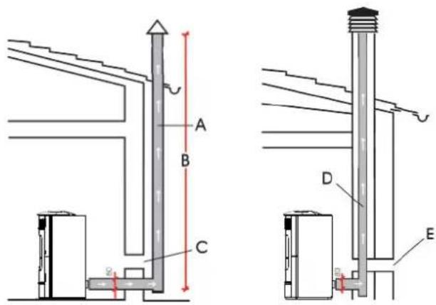
A: insulated steel chimney flu, Insulated
B: minimum height 1.5 m, and however beyond the eaves of the roof
C-E: air intake from outside (through section at least 80 cm²)
D: steel chimney flue inside existing masonry chimney flue
INSTALLATION
PLUMBING CONNECTION
The plumbing connection depends on the type of system. However, there are some “common rules”:
• The plumbing connection must be carried out by qualified personnel who can issue documentation declaring correct installation conforming to current law in each country (for example, in Italy according to Ministerial Decree 37/2008 and standard UNI 10412-2)
- The plumbing system must operate at a pressure between 1 and 1.5-2 bar on a hot closed-vessel circuit. Note: DO NOT install the stove in place of, for example, a thermocooker installed with an open vessel without an adequate expansion system making it a closed vessel.
- The separation of the primary from the secondary circuit is ideal and, in some countries, it is also mandatory in case of the installation of a heating plant (for example, in Italy, the reference is the Circular from ISPESL, now INAIL, of April 2011). This separation is easily carried out using KIT A2 from Edilkamin.
- The presence of a puffer (inertial storage tank) is recommended but not mandatory. Its presence has the advantage of freeing the stove from “sudden” demands from the heating system and allowing the integration of other heat sources. It reduces consumption and increases the efficiency of the system.
- The hot water exiting from the output of the stove must be "directed" differently depending on the objective (heating, radiators, exchanger, whether or not there is a puffer, etc.)
- The return temperature of the water at the stove must be at least 50 - 55^ to avoid condensation. Depending on the system, the installer must determine if anti-condensation valves or pumps are necessary.
- A puffer (inertial storage tank) is needed for heating any installed low-temperature under-floor heating panels according to the guidelines of the manufacturer of the panels. The under-floor panels should not receive water directly from the stove.
- The material used in the circuit must be suitable to withstand any overheating.
- The discharge of the safety valve must be accessible and visible.
The discharge water must be channelled into a vertical pipe using a funnel with backflow air intakes, appropriately spaced from the discharge point.
The conveying pipe must have the following characteristics: - Must not originate more than 50 cm from the discharge of the valve and must be positioned in the same room where the KIT is positioned.
- Must have a vertical expansion of not less than 30 cm. After which the pipe can continue horizontally with a gradient that fosters the flow of water.
- The diameter of the pipe must be at least one measurement larger than the nominal measurement of the discharge of the valve.
The end of the pipe must discharge into the sewer system. IT IS FORBIDDEN TO SHUT OFF THE DISCHARGE
- Verify that the hydraulic system is correctly installed and is equipped with an expansion tank that is sufficiently large to guarantee safety.
The presence of a tank within the boiler-stove does NOT guarantee appropriate protection from thermal expansion occurring in the whole system.
Therefore the installer must assess whether an additional expansion tank is needed, depending on the type of system installed.
- Fill the system using the filling tap (it is recommended not to exceed a pressure of 1,5 bar). When filling, 'bleed' the pump and the relief tap.
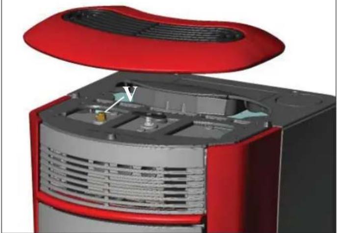
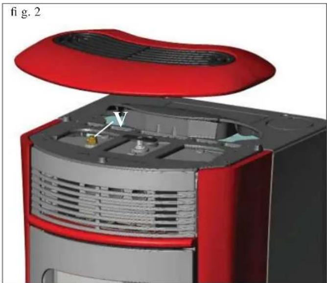
- It is possible that it will be necessary to open the vent (V - fi g. 2) during the initial days of operation to release air in the system.
natural_image
3D cutaway view of a red and gray electronic device showing internal components (no text or symbols)- Based on the type of water, the installer must determine whether or not to use conditioned products according to UNI 8065-1989 (treatment of water in heating systems for civil use).
- Due to the small diameter of the pipes themselves, direct connection to the radiators prevents normal operation.
- Below are several diagrams of "typical" installations provided by Edilkamin.
The accessories for their implementation are available from your dealer.
INSTALLATION
• HYDRAULIC CONNECTIONS:
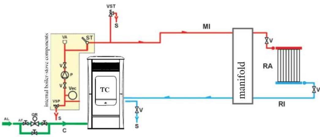
HEATING SYSTEM WITH THE THERMO STOVE AS THE ONLY HEAT SOURCE
flowchart
graph LR
    A["AL"] --> B["AF"]
    B --> C["GR"]
    C --> D["C"]
    D --> E["TC"]
    E --> F["S"]
    F --> G["VSP"]
    G --> H["V"]
    H --> I["P"]
    I --> J["VA"]
    J --> K["ST"]
    K --> L["VST"]
    L --> M["S"]
    M --> N["MI"]
    N --> O["manifold"]
    O --> P["V"]
    P --> Q["RA"]
    Q --> R["RI"]
    R --> S["V"]
    S --> T["VI"]
LEGEND
AF: Cold Water
AL: Water supply
C: Filling/Topping up
GR: Filling unit
MI: Outlet to system
P: Pump (circulator)
RA: Radiators
RI: Inlet from system
S: Drain
ST: Temperature Detector
TC: Boiler-stove
V: Ball valve
VA: Automatic bleed valve
Vec: Closed Expansion Tank
VSP: Safety Pressure Valve
VST: High Temperature Drainage Valve
HEATING SYSTEM WITH THE THERMO STOVE COMBINED WITH A BOILER
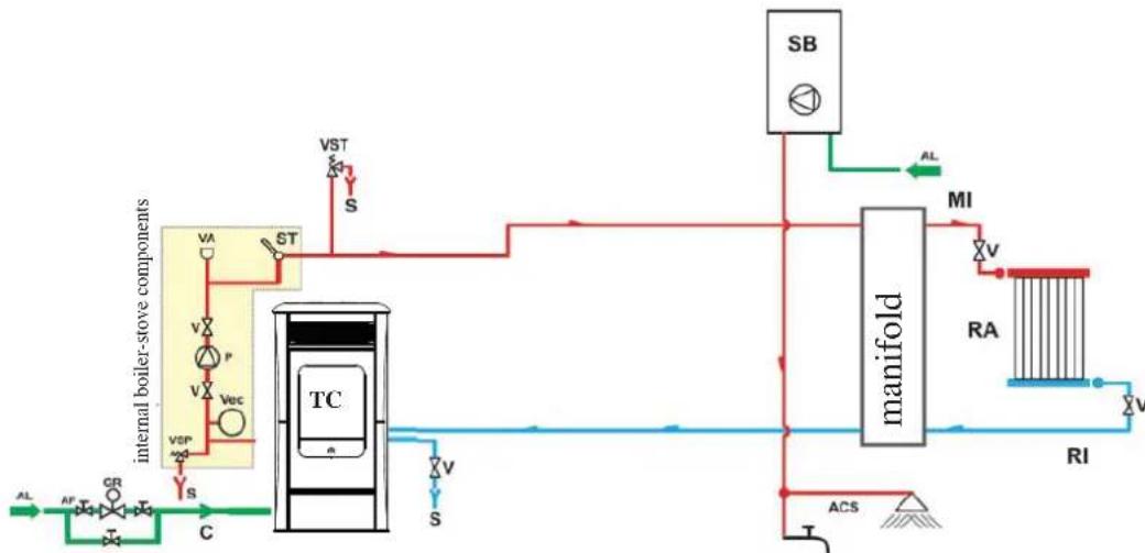
flowchart
graph TD
    A["internal boiler-stove components"] --> B["TC"]
    B --> C["Manifold"]
    C --> D["RA"]
    D --> E["RI"]
    E --> F["ACS"]
    F --> G["S"]
    G --> H["VST"]
    H --> I["S"]
    I --> J["STA"]
    J --> K["VA"]
    K --> L["V"]
    L --> M["P"]
    M --> N["V"]
    N --> O["VSP"]
    O --> P["S"]
    P --> Q["C"]
    Q --> R["AL"]
    C --> S["MI"]
    S --> T["SB"]
    T --> U["AL"]
    style A fill:#f9f,stroke:#333
    style C fill:#ccf,stroke:#333
    style D fill:#cfc,stroke:#333
    style E fill:#fcc,stroke:#333
LEGEND
ACS: Household hot water
AF: Cold water
AL: Water supply input
C: Fill/Top up
GR: Pressure reducer
MI: System in
P: Pump (circulation)
RA: Radiators
RI: System return
S: Drain
SB: Water boiler
ST: Temperature probe
TC: Boiler-stove
V: Spherical valve
VA: Automatic air vent
Vec: Closed surge tank
VSP: Safety valve
VST: Thermal discharge valve
HEATING SYSTEM WITH THE THERMO STOVE AS THE ONLY SOURCE OF HEAT, WITH SANITARY HOT WATER BEING PRODUCED BY A BOILER
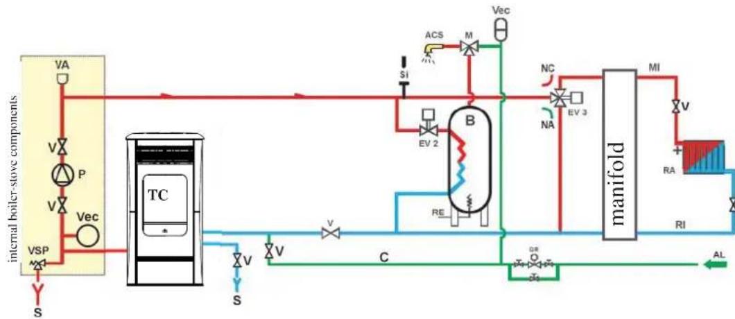
flowchart
graph TD
    A["internal boiler-stove components"] --> B["TC"]
    B --> C["Valve"]
    B --> D["Pump"]
    B --> E["Vac"]
    B --> F["VSP"]
    B --> G["S"]
    B --> H["V"]
    B --> I["S"]
    B --> J["V"]
    B --> K["V"]
    B --> L["C"]
    L --> M["Manifold"]
    M --> N["MEA"]
    M --> O["MEB"]
    M --> P["MEC"]
    M --> Q["MED"]
    M --> R["MEF"]
    M --> S["MEG"]
    M --> T["MEH"]
    M --> U["MEI"]
    M --> V["MEJ"]
    M --> W["MEK"]
    M --> X["MEL"]
    M --> Y["MEM"]
    M --> Z["MEN"]
    M --> AA["MEO"]
    M --> AB["MEP"]
    M --> AC["MEQ"]
    M --> AD["MER"]
    M --> AE["MES"]
    M --> AF["MET"]
    M --> AG["MEU"]
    M --> AH["MEV"]
    M --> AI["MEW"]
    M --> AJ["MEX"]
    M --> AK["MEY"]
    M --> AL["MEZ"]
    M --> AM["MEA"]
    M --> AN["MEB"]
    M --> AO["MEC"]
    M --> AP["MED"]
    M --> AQ["MEF"]
    M --> AR["MEG"]
    M --> AS["MEH"]
    M --> AT["MEU"]
    M --> AU["MEV"]
    M --> AV["MEW"]
    M --> AW["MEX"]
    M --> AX["MEY"]
    M --> AY["MEZ"]
    M --> AZ["MES"]
    M --> BA["MET"]
    M --> BB["MEW"]
    M --> BC["MEX"]
    M --> BD["MEY"]
    M --> BE["MEZ"]
    M --> BF["MES"]
    M --> BG["MET"]
    M --> BH["MEW"]
    M --> BI["MEX"]
LEGEND
ACS: Household hot water
AL: Water supply input
B: Boiler
C: Fill/Top up
EV2: 2-way electro-valve
EV3: 3-way electro-valve NA: Normally Open NC: Normally Closed
GR: Pressure reducer
MI: System in
P: Pump (circulation)
RA: Radiator
RI: System return
S: Drain
TC: Boiler-stove
V: Spherical valve
Vec: Closed surge tank
VSP: Safety valve
This layout is purely indicative. Have a plumber design and install the system.
ACCESSORIES:
In the diagram shown above, the use of the accessories available on the EDILKAMIN S.p.A. pricelist is assumed. Individual spare parts are also available (exchanger, valves, etc). For information, please contact your local dealer.
COVERING INSTALLATION
natural_image
Cross-sectional diagram of a portable air conditioner unit with labeled component C, showing internal structure and housing (no text or symbols beyond labels)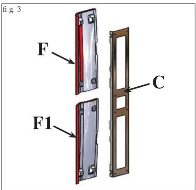
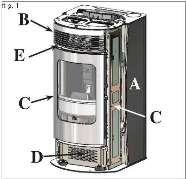
1) VERSION WITH CERAMIC SIDES AND TOP
Fig. 1 The stove is delivered (Fig. 1) with the following external components already installed:
- metal sides (A-B)
• metal frames for fastening the ceramic side elements (C)
• Upper/lower metal front (D-E).
The pieces indicated below are packaged separately.
• 2 upper ceramic side elements (F - Fig. 3)
• 2 lower ceramic side elements (F1 - Fig. 3)
• 1 lower ceramic side element (G - Fig. 4)
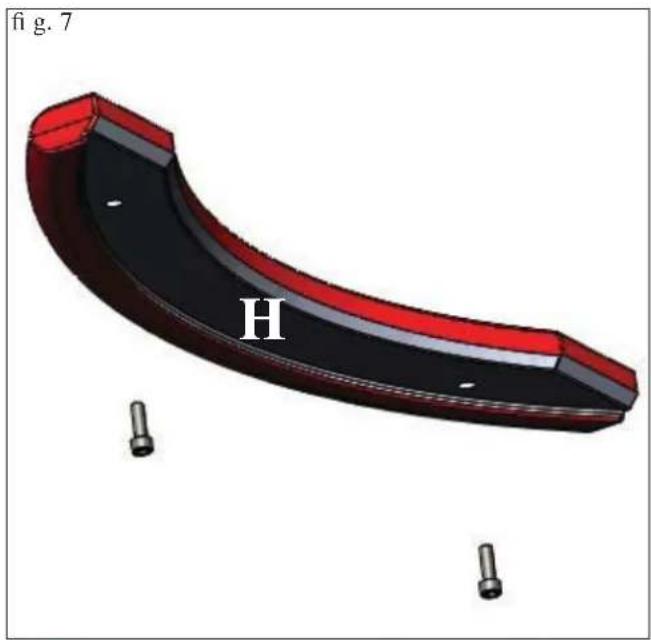
• 1 upper ceramic side element (H - Fig. 7)
• 1 ceramic top (I - Fig. 9)
- 18 milled pins M4
- 18 washers
- 4 springs (G1)
- 4 M4 screws
- 6 rubber pads (M)
Tofi t proceed as follows:
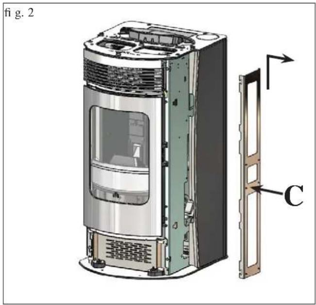
Fig. 2 Remove the two metal frames (C) from the stove by raising them and sliding them outwards.
Fig. 3 Fit the metal fastening frames (C) on the back of the vertical ceramic elements (F-F1) using the holes and the M4 milled pins provided (8 for each side).
COVERING INSTALLATION
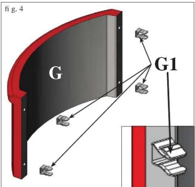
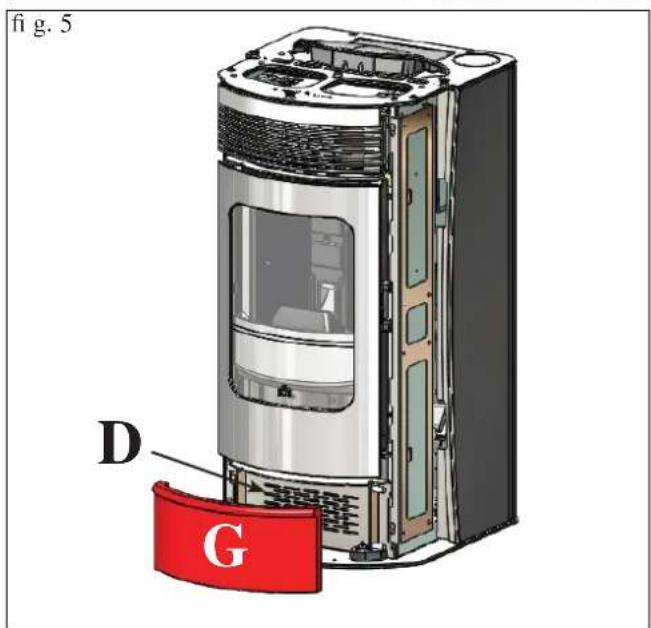
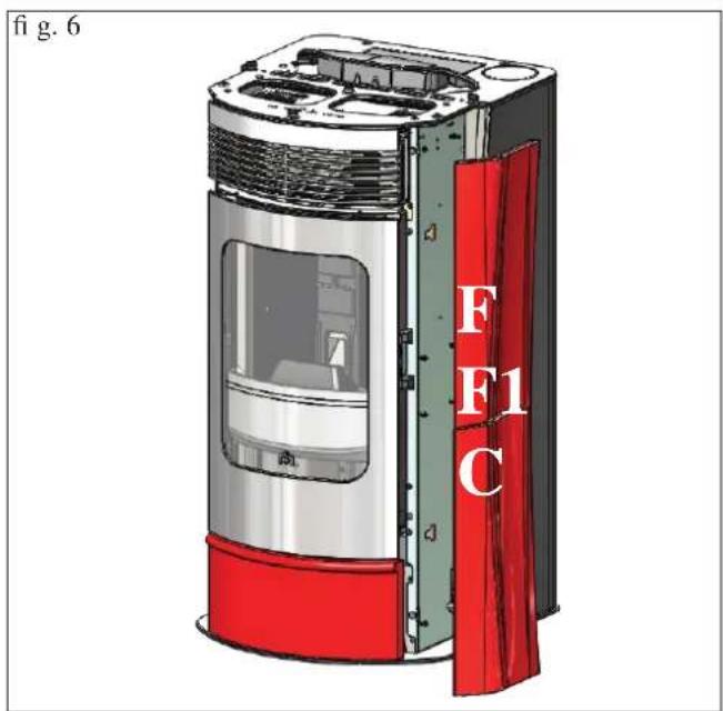
Fig. 4
Fit the fastening springs (G1) on the back of the lower ceramic front piece (G) using the holes and 4 M4 screws provided.
Note: the springs must be mounted with the strike plate facing outwards as detailed in Figure 4.
Fig. 5
Fit the lower ceramic front piece (G), complete with springs (G1) onto the pins on the metal front (D)
Fig. 6
Mount the vertical elements (F-F1), complete with the metal frame brackets (C) previously removed from the stove, on the structure.
COVERING INSTALLATION
natural_image
3D model of a curved mechanical component with red and black sections, marked with 'H' and two small pins (no text or symbols on the object itself)Fig. 7 Lightly tighten the 2 milled M4 pins provided on the back of the upper ceramic element (H).
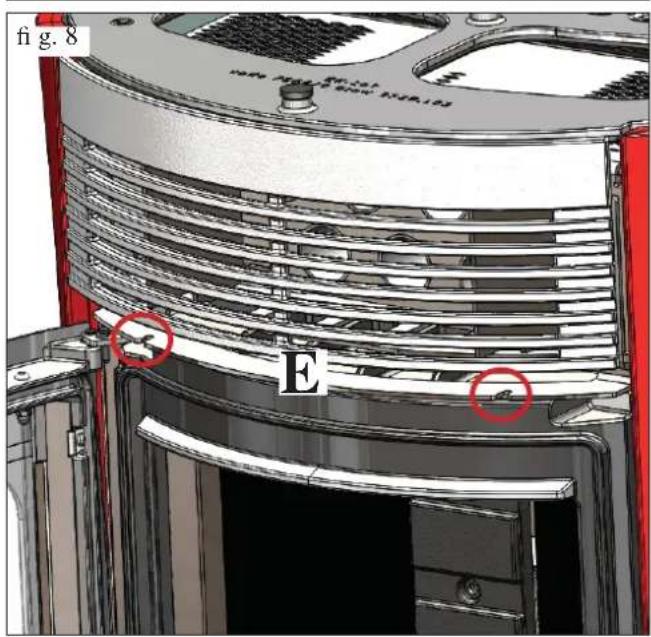
Fig. 8 Open the door and insert the upper ceramic element (H), complete with milled pins, on the slots on the upper metal front piece (E) and tighten by hand.
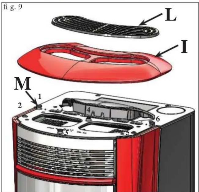
Fig. 9 Apply the 6 rubber pads (M) provided to the seats on the cast-iron top and position the ceramic top (I) and the cast-iron grate (L).
COVERING INSTALLATION
fig. 10
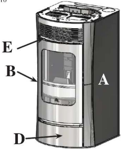
fig.11
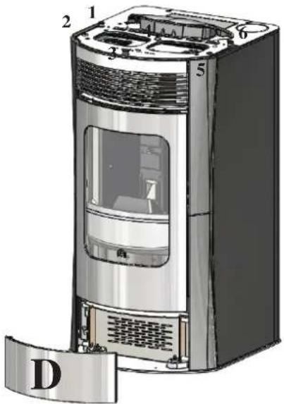
fig. 12
natural_image
Illustration of a modern electric heater with red and black casing (no text or symbols)2) VERSION WITH STEEL SIDES AND CERA- MIC PROFILES AND TOP
Fig. 10
The stove is delivered (Fig. 1) with the metal side (A-B) and the metal lower/upper front parts (D-E) already mounted.
The pieces indicated below are packaged separately.
- 2 horizontal upper/lower ceramic elements (H - Fig. 7 on page 10)
• 1 ceramic top (I - Fig. 9 on page 32) - 4 milled pins M4
- 4 washers
- 6 rubber pads
Tofi t proceed as follows:
Fig. 11
Remove the slotted-in lower front piece (D) and install the two ceramic lower/upper horizontal elements (H) as shown in Figure 7-8 on page 10.
Apply the 6 rubber pads provided to the seats on the cast-iron top and position the ceramic top (I) and the cast-iron grate (L).
Replace the slotted-in lower metal front piece (D).
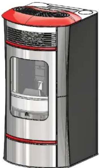
Fig. 12
The figure shows the stove completely assembled.
INSTRUCTIONS FOR USE
1st ignition/test by the Edilkamin authorised Dealer
Commissioning must be done as laid down in the UNI 10683 standard.
This standard indicates the control operations to be carried out in situ, aimed at ascertaining correct system function.
Edilkamin's Technical Assistance staff (CAT) will also calibrate the boiler-stove based on the pellet type used and the installation conditions (e.g. features of the fl ue).
Edilkamin's Technical Assistance staff (CAT) must commission the boiler in order for the guarantee to be activated.
The DEALER must also:
- Verify that the hydraulic system is correctly installed and is equipped with an expansion tank that is sufficiently large to guarantee safety.
The presence of a tank within the boiler-stove does NOT guarantee appropriate protection from thermal expansion occurring in the whole system.
Therefore the installer must assess whether an additional expansion tank is needed, depending on the type of system installed.
- Connect the electrical power to the boiler and implement a cold test (to be carried out by the DEALER).
- Fill the system using the filling tap (it is recommended not to exceed a pressure of 1,5 bar).
When fi lling, 'bleed' the pump and the relief tap.
There may be a slight smell of paint the first few times it is ignited, however, this will disappear quickly.
Before igniting you must check:
• that installation is correct
• the power supply
• that the door closes properly to a perfect seal
• that the combustion chamber is clean
- that the display is on stand-by (time and temperature set).
FILLING THE PELLET HOPPER
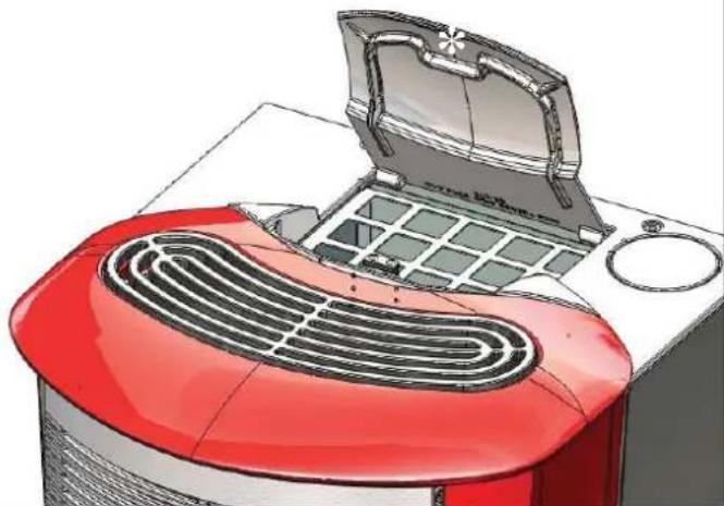
the hopper lid opens and closes with a practical click-clack system. simply apply slight pressure to the front part of the cast iron lid * (Fig. 1).
ATTENTION:
Use the glove supplied when filling the stove whilst it is running and therefore is hot.
fig. 1
natural_image
Illustration of a red portable air fryer with a lid open, showing its grille and vent (no text or symbols)fig.2
natural_image
3D cutaway view of a red and black electronic device showing internal components (no text or symbols visible)Attention:
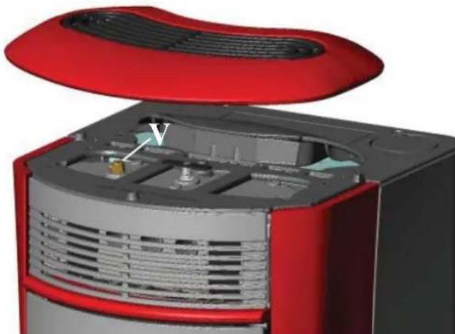
When igniting for the first time, do an air/water purge using the manual valve (V - fi g. 2) on the front of the top.
The operation must be repeated during the first days of use and in the event the plant has only been partially reloaded.
The presence of air in the ducts does not allow for proper operation.
To facilitate venting operations, the valve is fitted with rubber hoses.
NOTE regarding the fuel.
Boiler-stove is designed and programmed to burn wood pellets with 6 mm diameter. Pellets are a type of fuel in the form of little cylinders, made from compacted sawdust, compressed under high pressure with no adhesives or foreign materials. They are sold in bags of 15 kg.
For the boiler to function properly, you MUST NOT burn anything else in it. Using other materials (including wood) will render the warranty null and void. Such use is detected by laboratory analyses.
Edilkamin has designed, tested and programmed their boiler-stoves to guarantee the best performance when pellets with the following characteristics are used:
- diameter: 6 millimetres
- maximum length: 40 mm
- maximum moisture content: 8%
- calorifi c value: at least 4100
If pellets with different characteristics are used, the boiler-stoves must be recalibrated – a similar procedure to that carried out by the DEALER when the boiler is ignited the first time. Using unsuitable pellets may: decrease efficiency; cause malfunctions; stop the boiler-stove from functioning due to clogging, dirt on the glass, unburnt fuel, etc.
A simple, visual analysis of the pellets may be carried out:
Good quality: smooth, uniform length, not very dusty.
Poor quality: with longitudinal and transverse cracks, very dusty, various lengths and mixed with foreign matter.
INSTRUCTIONS FOR USE
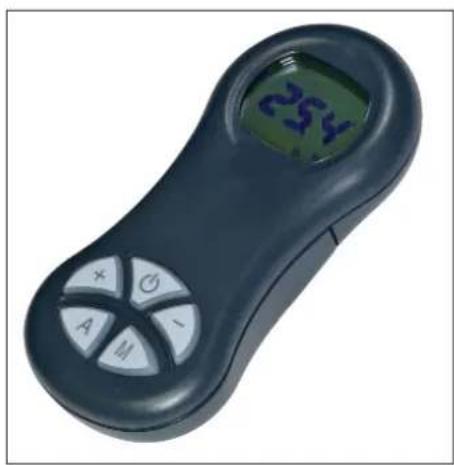
REMOTE CONTROL
This controls all the functions.
Key to buttons and display:
: to turn off and on (to go from "remote control on standby" to "remote control on")
+/- : to increase/decrease the various regulations
A : AIR key: to adjust the functioning of the fan in OFF-AUTO or manual mode F1, F2, F3, F4, F5
M : MENU' key: press quickly to set the "Comfort Clima" mode or the power mode. Press for 2 seconds to access to the various programming menus
natural_image
Close-up of a black handheld electronic device with a green display showing '254' and control buttons (A, M, +, -) on its body.
- icon flashing: remote control searching for network
- icon fi xed: remote control with connection enabled
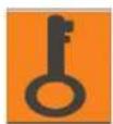
keypad locked (press "A" and "M" in parallel for a few seconds to lock or unlock the keypad)

fl at battery (3 mini alkaline batteries type AAA)
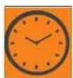
programming enabled
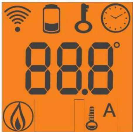
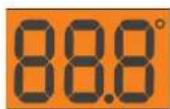
alphanumeric display consisting of 16 fi gures arranged in two lines of 8 fi gures

- icon fl ashing: boiler-stove turning on
- icon fi xed: boiler-stove working
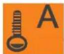
automatic function (display shows temperature)
In addition to the above-described icons, the display also gives other useful information.
- Stand-by position: shows the output temperature (TM), the set temperature (SET), the Kg of pellets (15Kg) remaining in the hopper and the current time.
- During the ignition phase: START-UP as well as the information shown in stand-by mode
- When operating: shows the output temperature (TM), the set temperature (SET), the Kg of pellets (15Kg) still in the hopper and the current time.
DO NOT PRESS THE BUTTON MORE THAN ONCE

Note: If the radio control is not used for a few seconds, the display will go dark as it has moved into the power-saving function. The display can be reactivated by pressing any button.
VENTILATION ADJUSTMENT:
By pressing key A, the display will show the AIR setting, one of three different ventilation modes can be selected:
OFF: ventilation is off even when the stove is operating
AUTO: ventilation is activated automatically according to a programme for the issue of power designed by the manufacturer MANUAL: Ventilation functions only when the stove is operating; there are 5 fixed ventilation levels to choose from, starting from the minimum (silent) F1 up to the maximum F5.
INSTRUCTIONS FOR USE
Filling the cochlea.
The first time you use the product, or should the tank be completely emptied of pellets, to fill the cochlea press both keys “+” and “-” on the remote control at the same time, holding for a few seconds. As you release the keys, the display should show the wording “LOAD”.
This should be carried out before ignition if the boiler-stove has stopped due to having run out of pellets, at the end of operation to empty the combustion pot before turning.
It is quite normal for some pellets to remain, that the cochlea cannot suction.
Automatic igniting.
With the boiler-stove on stand-by, press and hold the key ▼, on the remote control for 2 seconds. This will start-up the ignition procedure, showing the wording “START”.
At the same time, a countdown in seconds begins (from 1020 to 0). Ignition is not at a preset time, however: its duration is automatically shortened if the board reports that certain tests have been passed. The flame appears after about 5 minutes.
Manual igniting.
Temperatures of below 3^ C will not allow the electrical resistance to heat sufficiently. In this case, or should the resistance be temporarily out of action, Diavolina ^® type fi restarters can be used.
Insert a piece of lit Diavolina into the combustion chamber, close the door and press 🚙 the remote control.
OUTPUT TEMPERATURE ADJUSTMENT:
The SET output temperature can be altered by pressing the keys +/-.
ENVIRONMENT TEMPERATURE ADJUSTMENT:
By activating the COMFORT CLIMA (CAT) function with the +/- keys, the remote control device can be used as a mobile thermostat/chronothermostat: place it in the home in a position where the set temperature is desired, select COMFORT CLIMA with the menu key; the display will show the environmental temperature (AIR) and the desired environmental temperature (SET); adjust the desired temperature with the +/- keys and the remote control device will automatically send the request to the stove.
Turning off
With the boiler-stove running, press and hold the key ▼ from the remote control for 2 seconds. The turn-off procedure will begin, showing a countdown on the display from 9 to 0 (for a total of 10 minutes).
The turn-off phase involves:
- Interruption of pellet supply
- Smoke expulsion motor
- Circulator
Unless otherwise set, managed by the CAT.
Never pull the plug out whilst the device is still in the process of turning off.
N.B.: the circulator will continue turning for 5 - 10 minutes after switching off.
OPERATIONS THAT CAN ONLY BE CARRIED OUT BY REMOTE CONTROL
Clock regulation
Press and hold the key “M” for 2 seconds to access the “Clock” menu. This allows you to set the internal electronic board clock. By then pressing the key “M”, the following data appears in sequence and can be regulated:
day, month, year, hour, minutes, day of the week.
The wording “SAVE?” will appear for confirmation with “M”. This will allow you to check that the operations performed are correct, prior to completion (the wording “SAVE” will then be shown on the display).
Operations for switching on, switching off and changing the SET temperature can be carried out by means of the red emergen-cy button placed on the back of the boiler-stove (see page 52).
Weekly timer
Press and hold the “M” key on the remote control for 2 seconds. This turns on the clock regulation and by pressing the ‘+’ key, the weekly timer function is accessed, with the display showing the description “PROGRAMM ON/OFF”.
This function allows you to select the type of programming, which allows a maximum of three ignitions to be set.
As you confirm the display with the key "M", one of the following options will appear:
NO PROG. (no programme set)
DAILY PROGRAM (single programme for every day of the week)
WEEKLY PROGRAM. (specific programme for each day individually)
Use the “+” and “-” keys to switch between programmes.
Confirming by pressing the “M” key “DAILY PROGRAM.” and pressing the “+” key, the choice of the number of programmes (ignition/extinguishing) per day can be made.
Use the “DAILY PROGRAM” to set identical programme/s for every day of the week.
By then pressing the “+” key, the following can be seen: - Prog. no.
- 1st prog. (one turn on and one turn off per day), 2nd prog. (identical), 3rd prog. (identical)
Use the “-” key to show in reverse order.
If the 1st programme is selected, the turn on time is shown.
The display shows: 1 “ON” at 10 Use the “+” and “−” key to change the hour. Confirm with the “M” key (All 1 On/Hour 10).
The display shows: 1 "ON" at 30 Use the "+" and "-" key to change the minutes. Confirm with the "M" key (1 Off min).
The same applies for the turn-off time to be set and for subsequent turning on and off.
Confirm by pressing "M" and the wording "SAVE??" will appear on the display.y.
When confi rming "WEEKLY PROGRAM", you will need to choose the day to which the programming is to apply:
7 Sat; Progr.1; 1 Mon ; 2 Tues; 3 Wed; 4 Thurs; 5 Fri; 6 Sa;
Once the day is set, use the keys “+” and “+” and confirm by pushing the “M” key to choose 1 to 3 ignitions, to programme in the same way as for the “DAILY PROGRAM”, choosing whether or not to enable a programme for each day of the week, and if so choose the number of interventions and at what times.
Should you make an error during programming, you can leave the programme without saving. As you press a key, ▼, the display will show the word "no SAVE".
INSTRUCTIONS FOR USE
Pellet-loading adjustment: (with self-regulation deactivated). Press and hold the menu key for two seconds to gain access to the language menu, use the + key to find the "ADJ PELLET" menu, con-firm the menu with the M key, and the message "PELLET ADJ 00%" will appear on the display. The pellet drop can be adjusted manually by changing the capacity in percentage terms (+/- 30 %). By conf rming this function with the menu key, you can access the function to adjust pellet loading. By decreasing the value set, pellet loading is decreased. By increasing the value set, pellet loading increases. This function is useful if changing the pellet type for which the stove has been calibrated and loading therefore needs correcting.
Should this correction not suffice, contact the Edilkamin-authorised Dealer, to establish the new operating axis.
Notes on flame variability
Flame status may vary depending on the type of pellet used, in addition to normal solid fuel flame variability and regular combustion chamber cleaning carried out automatically by the boiler.
(N.B.: which does NOT replace necessary cold suction by the user prior to ignition).
RESERVE WARNING
The boiler-stove is fitted with an electronic function that detects the residual quantity of pellets in the tank.
The detection system is integrated into the electronic board, allowing you to see how many hours and kg are left until pellet exhaustion, at all times. For correct system function, it is important that the following procedure is followed during the first ignition (by the Dealer).
This provides a reference indicator.
Greater precision is obtained by regularly zeroing the system before filling it again. Edilkamin does not accept any responsibility for differences from what is indicated (which may be due to external factors).
Pellet reserve system
Before enabling the system, you need to load a sack of pellets into the tank and use the stove until the loaded fuel has run out. This allows for a short system road test.
After this, the tank can be filled completely and the stove started up.
When running, at the time at which a whole 15 kg sack of pellets can be loaded, the display will show the word "Reserve" flashing.
At this point, after having poured in a sack of pellets, you need to 'inform' the memory that you have loaded 15 kg.
To do so, proceed as follows:
-
press the "M" key (for approximately 3-4 seconds) until the word "LANGUAGE" appears.
-
press the "+" key until the word "Reserve pellet" appears.
-
press the "M" key until the following screen appears,
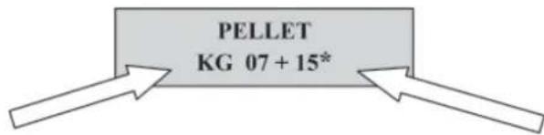
Kg remaining in tank
Kg loaded
then use the “+” key to take the figure (*) to the value equal to the Kg of pellets loaded (15 kg in the above example).
- press the "M" key to confirm
- press the key ▼ to exit.
After having completed the above procedure, after having consumed the 15 kg, the wording “Reserve” will appear flashing at intervals.
The operation can then be repeated, proceeding from point 1 to point 5, every time you wish to load pellets (optional).
EMERGENCY BUTTON
If the radio remote control device does not work, you can carry out the basic functions by means of a red emergency button positioned on the back of the stove (see Fig. 1).
Push this button once or more times to activate the required function:
- BOILER-STOVE OFF
by pressing the red button for 2 seconds this turns on.
- BOILER-STOVE ON
by pressing the red button for 2 seconds this turns off.
- BOILER-STOVE ON
manual mode, by pressing the red button, you go from P1 to P3.
- BOILER-STOVE ON
If the stove is set in power mode, press it quickly to change the SET output, increasing it cyclically from 50 to 80°C; if set in “comfort clima”, the desired environmental temperature can be increased cyclically from 10 to 30°C
INSTRUCTIONS FOR USE
THE ELECTRONIC CIRCULATOR
(low-consumption pump)
The product has a circulator with an electronic motor to save electricity and comply with the European regulations.
Electronic control of operation:
a) Control mode p - c
In this mode, the electronic controller keeps the differential pressure generated by the pump at a constant set value of H s.
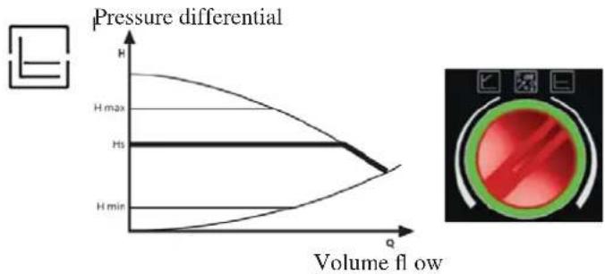
line
| Volume flow | Pressure differential | | ----------- | -------------------- | | 0 | H | | 1.5 | H max | | 2.0 | Hs | | 2.5 | H min |b) Control mode p - v
In this mode, the electronic controller varies the pressure differential between the set value Hs and 1/2 H s. The pressure differential varies with the volume flow.
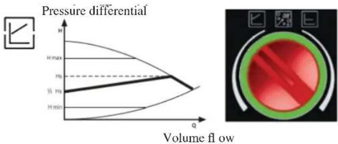
line
| Volume flow | Pressure differential | | ----------- | -------------------- | | ½ Hs | ½ Hs | | Hs | Hs | | Hmax | Hmax | | Hmin | Hmin |c) Venting procedure
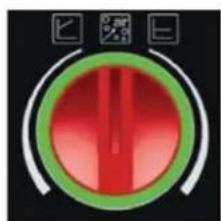
This procedure allows the expulsion of air present in the hydraulic circuit.
After manual selection of the "AIR" mode, the pump will automatically alternate between maximum and minimum speed for 10 minutes.
At the end of the procedure, the circulator will go to the pre-set speed. You can then select the desired mode of operation
We summarize the signals that low-consumption circulators can display with the LEDs located on the pump controls
| LED | Green led on | The green led fl ash quickly | The led fl ash with light red/green | The led fl ash with red light | Led off |
| MEANING | Working pump | The pump is ready to work but doesn't turn | Pump out of service | No supply voltage | |
| WORK CONDITION | The pump works in base of its settings | The pump works 10 minutes to purge the air. After it is necessary to set the power | The pump will start to work automatically when the problem is solved | The pump is stopped (blocked) | The pump doesn't receive the voltage |
| CAUSE | Normally work | Normally work | - under-voltage U < 160V overvoltage U > 253V- Engine temperature too high | The pump doesn't start automatically | - The pump isn't connected on the motherboard- The led is defective- The pump is defective |
| RESOLUTIVE AC-TION | - Check the vol-tage 195V < U < 253V- Check the water temperature | Change the pump | - Check the wire connection- Check if the pump works- Change the pump |
natural_image
Circular red indicator dial with green ring, no visible text or symbolsMAINTENANCE
Before performing any maintenance, disconnect the appliance from the mains.
Regular maintenance is required for the boiler-stove to function correctly.
Any problems resulting from lack of maintenance will immediately void the warranty.
When cleaning is necessary, the message “Clean - exchanger” will appear on the panel if further cleaning is necessary.
NOTE: The DEALER, upon commissioning, sets the kg value of consumed pellets; after which, the message "SERVICE UTE" will appear on the display. The boiler-stove continues operation, but the end client is invited to perform careful maintenance, described above and explained by the DEALER during commissioning, to the extent of his abilities. Once the maintenance work has been performed, press and hold down the "M" button on the radio remote control for at least 5 seconds to delete the message displayed on the screen (this operation must be performed with the thermo-stove off).
N.B.
- Any unauthorised modification is forbidden
- Use spare parts recommended by the manufacturer
- The use of counterfeit parts results in the guarantee becoming null and void
DAILY MAINTENANCE
Operations must be performed when the boiler-stove is off, cold and unplugged from the power supply.
Cleaning should be carried out with the aid of a vacuum cleaner (see optional page. 60), the whole procedure takes up a few minutes.
- Open the door, remove the combustion chamber (1 - fig. A) and empty the residue out into the ash pan.
- Scrap the combustion chamber with the spatula provided, removing any obstructions in the openings.
• DO NOT EMPTY THE RESIDUE OUT INTO THE PELLET HOPPER.
• Take out and empty the ash (2 - fig A) pan into a fireproof container (the ash may still contain hot parts and/or embers).
• Vacuum clean the inside of the fireplace, the fire surface, the compartment around the chamber where ash falls, and the ash pan.
• Vacuum the combustion chamber holder, clean the edges where the combustion chamber is lodged into its seat. - Clean the glass, if necessary (when cold).
AT LEAST ONCE A DAY ACTION THE CLEANING BRUSHES OF THE EXCHANGERS (\*), EVEN WHILE THE STOVE IS LIT, USING THE GLOVE PROVIDED:
- Proceed shaking the cleaning handle under the ceramic top (* fi g. B).
NEVER SUCTION HOT ASH, as this could damage the suction device and possibly cause a fire.
ATTENTION:
MAKE SURE THE ASH PAN IS CORRECTLY POSITIONED IN ITS HOUSING (2 fig. A)
WEEKLY MAINTENANCE
- Clean the hearth (with the tube brush).
• Vacuum the pipe near the electric coil (3 - fi g A).
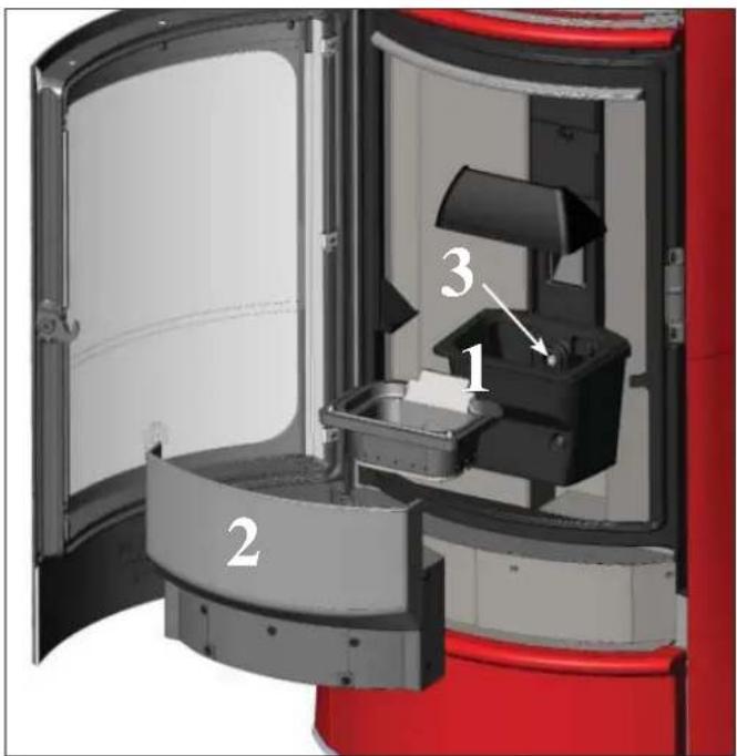
fig. A
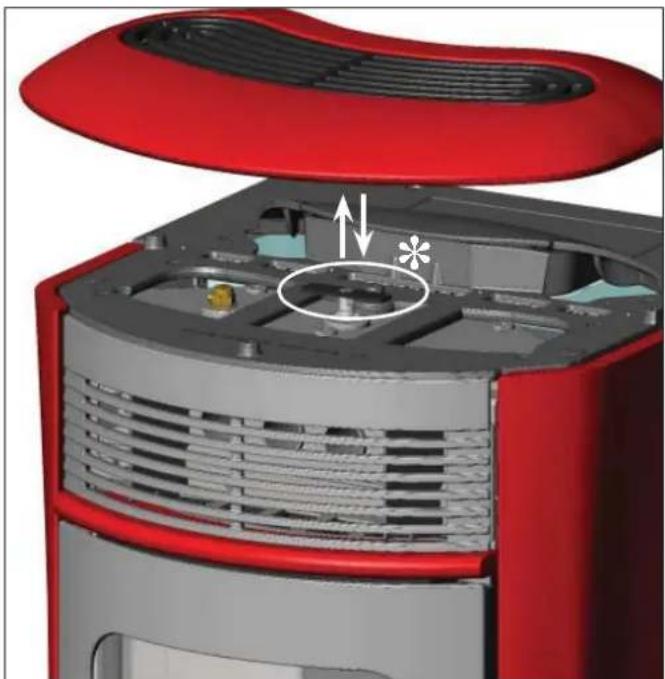
natural_image
3D cutaway view of a red and gray electronic device showing internal components and ventilation (no text or symbols)fig.B
MAINTENANCE
SEAS ONAL MAINTE NANCE
(implemented by the DEALER) Consists in:
- Clean the boiler-stove internally and externally
- Carefully clean the heat exchange tubes
- Carefully clean and remove dirt from the combustion chamber and the relative compartment
- Clean fans, verify mechanical and clamp loosening
- Clean smoke channel (replace seals on smoke exhaust pipe)
- Clean smoke duct
- Check the expansion tank
- Check and clean the circulator
- Clean smoke extraction fan compartment.
- Clean smoke check thermocouple.
- Empty the pellet hopper and clean the base with the vacuum cleaner.
- Clean, inspect and scrape any residue from the ignition resistance compartment and if necessary, replace it
- Visually inspect the electrical wires, connections and power cable
- Check play of the screw-gear motor group
- Clean the pellet hopper and check loosening of the feed screw - gear motor assembly
- Replace the door seal
- Functionality test: load the feed screw, ignite, let it run for 10 minutes and shutdown
If the boiler-stove is used very frequently, it is advisable to clean the smoke channel and the fume duct every 3 months.
ATTENTION !!!
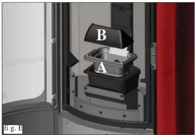
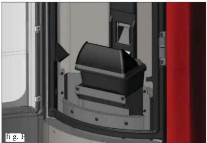
After implementing a normal cleaning procedure, INCORRE CT coupling of the upper (A) (figura E) and lower (B) (figura E) combustion chambers can compromise the boiler-stove's performance.
Before igniting the boiler-stove, make sure the combustion chambers are correctly paired as indicated in (fi g. F) without ash or unburnt material present on the support perimeter.
We remind you that using the stove without cleaning the melting pot, may cause a sudden ignition gas inside the combustion chamber with the consequent breaking of the glass
CLEANING THE SMOKE CHANNEL
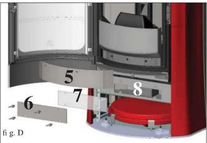
- When the stove is cold and in stand-by, shake strongly the cleaning bar (see previous page); remove the bottom ceramic tile (3 fig.C) and the metal cover (4 fig.C).
- Remove the sheet metal (5 – fig D) and the sheet panel inspection (6 – fig.D), with its scal gasket (7 fig.D), fixed by nuts. Clean the gasket and vacuum into the pipe
The thermo stove comes with a spare silicone gasket.
The quantity of residue which forms depends on the type of fuel and the type of system.
If cleaning is not carried out, the boiler-stove may not function properly.
Note: after the operation, make sure that the smoke duct inspection closure is correctly repositioned.
natural_image
3D rendering of a mechanical component with a black housing and red vertical panel, no visible text or symbols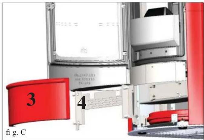
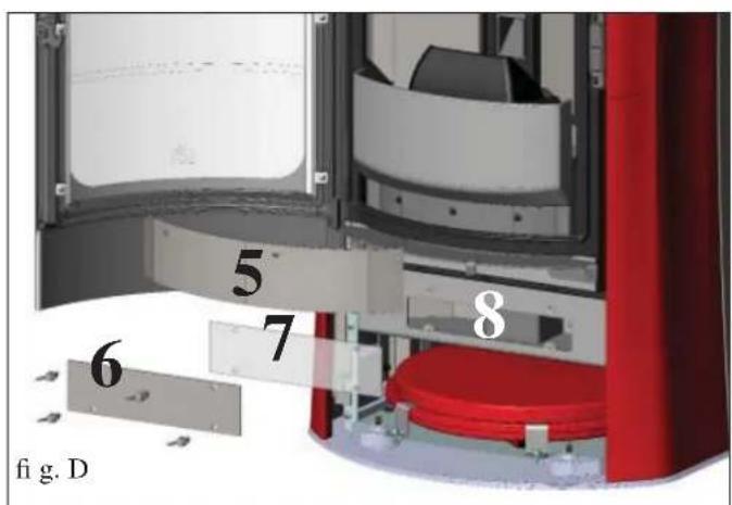
POSSIBLE TROUBLESHOOTING
In the event of problems the boiler-stove stops automatically and runs the shutdown process and the display shows text regarding the motivation of the shutdown (see the various alarms below).
Never pull the plug during shutdown on account of malfunction.
To start the boiler-stove up again after a shutdown, let the shutdown procedure end (10 minutes marked by a beep) tend then press the button ▼.
Do not turn the boiler-stove on again before checking the cause of the malfunction and CLEANING/ EMPTYING the crucible.
INDICATION OF POSSIBLE CAUSES OF MALFUNCTION AND INDICATIONS AND REMEDIES:
1) Signalling: H2O PTC\_FAULT
Problem: Shuts down due to the water temperature sensor being broken or disconnected.
Actions: - Check connection of the sensor to the control board. - Verify functionality by means of a cold test
2) Signalling: Verific./extract.: (this trips if the smoke extraction speed sensor detects a fault)
Problem: Shutdown for smoke extraction speed fault detection
Actions: • Check smoke extractor function (devolution sensor connection) and board (DEALER).
- Check smoke channel for dirt
- Verify the electrical system and earthing system.
- Check electronic circuit board (DEALER).
3) Signalling: Stop/Flame: (this trips if the thermocouple detects a smoke temperature lower than the value set, which it interprets as the absence of flames)
Problem: Turns off due to drop in smoke temperature
Flame may fail for any of the following reasons:
- lack of pellets
- too many pellets have suffocated the flame, check pellet quality (DEALER)
- the maximum thermostat has intervened (rare, this only intervenes in the event of excessive smoke temperature) (DEALER)
- The safety pressure switch comes on because of clogging/blockage of the smoke discharge pipe or the flue (have it checked by a qualified technician - chimney sweep)
- Activation of the safety thermostat of the tank. Check that around the stove there aren't any objects blocking the ventilation or whether the fans are broken or off, in which case call the DEALER.
4) Signalling: Block_FI/NO Start: (intervenes if a flame fails to appear within a maximum of 15 minutes, or if ignition temperature is not reached).
Problem: Turns off due to incorrect smoke temperature during ignition
Distinguish either of the following cases:
Flame does NOT appear
Actions: Check: - combustion chamber position and cleanliness;
- arrival of combustion air in the combustion chamber;
- if the heating element is working (DEALER);
- room temperature (if lower than 3^ C use a firelighter) and damp.
- Try to light with a fi relighter.
Flames appear, but AF appears on the display after Ar.
Actions: Check: (only by the Dealer)
- if the thermocouple is working (DEALER);
- start-up temperature setting in the parameters (DEALER).
5) Signalling: Black Out: (not a defect of the boiler-stove).
Problem: Turns off due to lack of electricity
Actions: • Check electricity connection and drops in voltage.
6) Signalling: Fault/RC: (intervenes if the thermo coupling has failed or is disconnected).
Problem: Turns off due to thermo coupling failed or disconnected
Actions: • Check connection of thermo coupling to board:
- Check function in cold test (DEALER).
POSSIBLE TROUBLESHOOTING
7) Signalling: smoke °C/high.: (turns off due to exceeding maximum smoke temperature).
Problem: Switching off due to exceeding the maximum smoke temperature.
Check (only by the Dealer):
- pellet type, anomaly in smoke extraction,
• smoke channel blocked,
- incorrect installation,
- gear motor 'drift'
8) Signalling: Check button (signals an anomaly on the emergency button)
Actions: • check maintenance status of the button and its board connection cable (DEALER).
9) Signalling: Verific./air flow: (intervenes if the flow sensor detects insufficient combustion).
Problem: Turns off for lack of depression
- Flow may be insufficient if there is a hatch open or the hatch is not perfectly sealed (e.g. seal flawed).
- This may also be the case if there is a problem with air intake or smoke extraction, or if the
- combustion chamber is blocked or the flow sensor dirty (clean with dry air).
- Also check that the flow sensor limits are within the parameters.
- The depression alarm may also be signalled during ignition, if the chimney flue does not comply with
- specifications or the chimney flue and chimney pot are clogged.
10) Signalling: H2O TEMPALARM (Activated if the water sensor is faulty or disconnected)
Problem: Shuts down due to water temperature being higher than 90 ^ .
An excessive temperature may occur because of the following:
- system too small: ask the DEALER to activate the ECO function
- blockage: clean the exchanger pipes, the combustion chamber and the smoke outlet.
11) Signalling: "Battery check"
Problem: The boiler-stove does not stop but the error appears on the display.
Actions: • The buffer battery of the control board needs changing (DEALER).
12) Signalling: HIGH CURRENT ALARM: Activated when anomalous, excessive current is being absorbed by the gear motor.
Actions: Check functioning (CAT): gear motor - Electrical connections and electronic board.
13) Signalling: LOW CURRENT ALARM: Activated when anomalous, insufficient current absorption is detected on the gear motor.
Actions: Check functioning (CAT): gear motor - pressure switch - tank thermostat - electrical connections and electronic board
14) Problem: Remote control not working
Actions: • Move closer to the boiler-stove
- check the battery and if necessary, replace it.
- Synchronisation with automatic search on activation: when you put the batteries into the radio control a radio channel search phase will start up automatically, and it will subsequently connect to the product detected. So that this occurs correctly, make sure to switch the product on before inserting the batteries in the radio control, and stay in the vicinity of the antenna in order to achieve radio coverage with certainty.
- Synchronisation with automatic search and manual activation - it is possible to launch an automatic search for a product manually, simply carry out the following operations after having already put the batteries into the radio control:
- Approach the device and make sure that it is connected to the mains electricity.
- With the display switched off (standby) hold the 0/I key down for 10".
- After 10" a "NETWORK SEARCH" message appears on the display, then release the o/I key, as this means that the automatic search has been activated. - Automatic tuning of the radio channel will occur within a few seconds.
POSSIBLE TROUBLESHOOTING
15) Problem: During ignition, the differential switch trips (DEALER):
Actions: • Check the condition of the ignition coil, the electrical system, and the electrical components.
16) Problem: Water is not hot enough:
Actions: • clean the hearth exchanger
NOTE 1
All signals/warnings remain shown until you intervene on the remote control, by pressing the button 📇.
Do not use the insert before having eliminated the problem.
NOTE 2
Once 1000 kg of pellets have been consumed or some other value set by the CAT during the first ignition, the display fl ashes a message that reads “maintenance”.
The boiler-stove works, but you must call the Dealer out to perform extraordinary maintenance.
NOTE 3
solid-fue due to the quality of pellets or particularly critical installation, the boiler-stove becomes clogged earlier, the message “CALL SERVICE” will appear. Proceed as per “Mainten.” instructions.
N.B.:
The combustion chambers and smoke ducts connected to the solid-fuel appliances must be cleaned once a year (check if your country has specific legislation covering this).
Failure to regularly check and clean increases the likelihood of a fire in the chimney pot.
IMPORTANT!!!
In the case of a fire in the boiler-stove, in the flue or in the chimney, proceed as follows:
- Disconnect the power supply
- Use a carbon dioxide (CO_2) extinguisher
- Call the fi re brigade
DO NOT ATTEMPT TO PUT THE FIRE OUT WITH WATER!
After the event, have the appliance checked by an authorised Service Centre and have an authorised technician check the flue.
FAQ
The answers are listed below in summary form, for further details see the other pages of this document.
1) What do I need to prepare in order to install the boiler-stove?
Flue pipe at least 80 mm in diameter or direct connection to the outside.
An air inlet in the room that is at least 80 cm ^2 .
^3/_4 " G outlet and inlet fi tting.
3/4" G drains connection for overpressure valve.
3/4" G load fi tting.
A certified electrical connection with a thermal magnetothermic switch 230V +/- 10% 50 Hz.
(assess the division of primary and secondary circuits).
2) Can the boiler-stove work without water?
NO. Use without water could damage the stove BEYOND REPAIR.
3) Does the boiler-stove generate hot air?
YES. Most of the heat produced is transferred to the water, while heat is released into the room in which the stove is installed by irradiation and a fan.
4) Can I connect the inlet and outlet of the boiler-stove directly to a radiator?
NO, just like other boilers, it must be connected to a collector from which the water is then distributed to the radiators.
5) Do boiler-stove also supply hot sanitary water?
Hot water can be produced by the use of a special kit, after having assessed the power of the stove in terms of the plumbing system.
Evaluate complementary solutions (e.g. solar) for the summer when you do not turn on the stove.
6) Can I discharge the smoke from the boiler-stoves along the wall?
NO, a discharge which is conform with standards (UNI 10683) must reach the ridge of the roof, and in any case proper functioning requires a vertical stroke of at least 1.5 meters; avoiding that in case of power outage or wind, a slight amount of smoke forms in the installation environment.
7) Do I need an air inlet in the room where it is installed?
Yes, to replenish the air used by the boiler-stove for combustion; a direct external connection is also possible.
8) What settings are required on the boiler-stove display?
The desired water temperature. The boiler-stove will then adjust the power accordingly to obtain or maintain this.
For small systems, a mode can be set that ignites and shuts down the boiler-stove accordingly, as the water temperature is reached. (contact DEALER for initial start up)
If an ambient thermostat has been installed, set the temperature of the room.
9) How often do I need to clean the combustion chamber?
Ideally before each time the stove is switched on, when the stove is off and cold. AFTER CLEANING THE EXCHANGER TUBES by means of the smoke-channel cleaning handle (see page 54).
10) Do I need to vacuum the pellet hopper?
Yes, at least once a month when the boiler-stove is not used for some time.
11) Can I burn other fuel apart from pellets?
NO. The boiler-stove has been designed to burn wood pellets that are 6 mm in diameter. Any other material can damage it.
12) Can I ignite the boiler-stove by sending an SMS?
Yes, by connecting a dialler to the serial port on the back of the stove using the optional cable
CHECK LIST
To be integrated with a complete reading of the technical specifications
Positioning and installation
• Commissioning done by an approved CAT that issued the guarantee
• Air vent in the room
• Only the boiler-stove outlet passes through the smoke channel/chimney flue
• Features of the smoke channel (stretch of duct connecting the boiler-stove to the flue/chimney):
a maximum of 3 curves
a maximum of 2 horizontal metres
• The exhaust pipes are made of suitable material (recommended: stainless steel)
• When using any flammable materials (e.g. wood), all precautions have been taken to prevent a fire hazard
• The heating capacity has been appropriately assessed considering radiator efficiency:
- The plumbing system is declared conforming the laws of the country (such as, in Italy, to Ministerial Decree 37, formerly Law 46/1990) by a qualified technician.
Use
• Good quality, dry wood pellets are used (diameter 6 mm) (maximum permissible humidity 8%).
• The chimney pot and ash compartment are clean and well positioned.
• The cleaning rods are moved every day.
• The exchanger tubes and internal parts of the hearth are clean.
• The smoke extract duct is clean.
• The bleeding process has been applied to the hydraulic system.
• The pressure (shown on the pressure gauge) is at least 1,5 bar.
REMEMBER TO VACUUM THE COMBUSTION CHAMBER BEFORE EACH IGNITION Should ignition fail, DO NOT re-ignite until you have emptied the combustion chamber.
OPTIONAL
TELEP HONE COMBINER FOR RE MOTE IGNITION
The boiler-stove can be ignited remotely by asking the DEALER to connect the telephone combiner to the serial port behind the boiler-stove via the optional cable (code 640560).
CLEANING ACCESSORIES
GlassKamin
Used for cleaning the ceramic glass
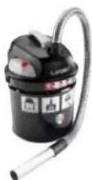
Ash vacuum cleaner
Used for cleaning the hearth
INFORMATION FOR USERS
In accordance with Art. 13 of the Legislative Decree No. 151, dated 25 July 2005, “Implementation of Directives: 2002/95/EC, 2002/96/EC and 2003/108/EC, pertaining to the reduction of hazardous substances used in electrical and electronic equipment, as well as disposal of waste”. The crossed-out wheeled bin symbol shown on the equipment or on the packaging indicates that the product must be disposed of separately at the end of its useful life. Therefore, at the end of the equipment’s useful life, the user must hand in the equipment to suitable collection facilities for electrical and electronic waste, or return it to the retailer when a new, equivalent appliance is purchased in a ratio of one to one.
NOTES
DATE AND STAMP INSTALLER
DATE AND STAMP CAT. FIRST IGNITION
DATE AND STAMP ANY SERVICING
DATE AND STAMP SEASONAL MAINTENANCE
DATE AND STAMP DEALER
DATE AND STAMP CAT.
For further clarification or requirements, visit our website www.edilkamin.com
NOTES:
TABLE DES MATIÈRES
INFORMATIONS GÉNÉRALES
• APPAREILS ÉLECTRONIQUES
natural_image
Close-up of a mechanical component with wires and a metallic housing, marked with asterisks (no readable text or symbols)INFORMATIONS GÉNÉRALES
LE THERMOPOÊLE EST DISPONIBLE DANS SIX VARIANTES ESTHÉTIQUES :
natural_image
3D cutaway view of a red and gray electronic device showing internal components (no text or symbols)MI: refoulement installation
RI: retour installation
S: évacuation
MI: refoulement installation
RI: retour installation
S: évacuation
SB: chauffe-bain
MI: refoulement installation
RI: retour installation
S: évacuation
TC: thermopoêle
V: soupape à bille
natural_image
Cross-sectional diagram of a portable air conditioner unit with labeled component C, showing internal structure and housing (no text or symbols beyond labels)
1) VERSION AVEC CÔTÉS ET TOP EN CÉRAMIQUE
natural_image
3D model of a curved mechanical component with red and black sections, marked with 'H' and two small bolts at the base (no text or symbols on the object itself)natural_image
Illustration of a modern electric heater device with red and silver casing (no text or symbols)natural_image
Illustration of a red electric heater with its hood open, showing airflow or ventilation system (no text or symbols)fig. 2
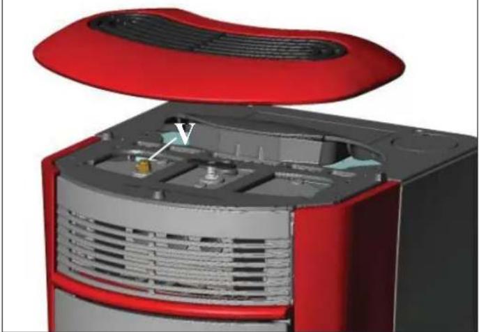
natural_image
3D cutaway view of a red and gray electronic device showing internal components (no text or symbols visible)Attention:
natural_image
Close-up of a black handheld electronic device with a green display showing '254' and control buttons (no readable text beyond basic symbols)
line
| Q | H | H max | Hs | H min | |------|-------|-------|------|-------| | 0 | High | High | High | Low | | 1 | Low | Low | Low | Low |line
| Q | H | H_max | H_s | H_min | |------|-------|-------|-------|-------| | 0 | 0 | 0 | 0 | 0 | | 1.5 | 0 | 0 | 0 | 0 | | 3 | 0 | 0 | 0 | 0 | | 4.5 | 0 | 0 | 0 | 0 | | 6 | 0 | 0 | 0 | 0 | | 7.5 | 0 | 0 | 0 | 0 | | 9 | 0 | 0 | 0 | 0 | | 10.5 | 0 | 0 | 0 | 0 | | 12 | 0 | 0 | 0 | 0 | | 13.5 | 0 | 0 | 0 | 0 | | 15 | 0 | 0 | 0 | 0 | | 16.5 | 0 | 0 | 0 | 0 | | 18 | 0 | 0 | 0 | 0 | | 19.5 | 0 | 0 | 0 | 0 | | 21 | 0 | 0 | 0 | 0 | | 22.5 | 0 | 0 | 0 | 0 | | 24 | 0 | 0 | 0 | 0 | | 25.5 | 0 | 0 | 0 | 0 | | 27 | 0 | 0 | 0 | 0 | | 28.5 | 0 | 0 | 0 | 0 | | 3 | 1.5 | 1.5 | -1.5 | -1.5 | | 3.5 | -1.5 | -1.5 | -2.5 | -2.5 | | 4 | -2.5 | -2.5 | -3.5 | -3.5 | | 4.5 | -3.5 | -3.5 | -4.5 | -4.5 | | 5 | -4.5 | -4.5 | -5.5 | -5.5 | | 5.5 | -5.5 | -5.5 | -6.5 | -6.5 | | 6 | -6.5 | -6.5 | -7.5 | -7.5 | | 6.5 | -7.5 | -7.5 | -8.5 | -8.5 | | 7 | -8.5 | -8.5 | -9.5 | -9.5 | | 7.5 | -9.5 | -9.5 | -10.5 | -10.5 | | 8 | -10.5 | -10.5 | -11.5 | -11.5 | | 8.5 | -11.5 | -11.5 | -12.5 | -12.5 | | 9 | -12.5 | -12.5 | -13.5 | -13.5 | | 9.5 | -13.5 | -13.5 | -14.5 | -14.5 | | 10 | -14.5 | -14.5 | -15.5 | -15.5 | | 10.5 | -15 | -15 | -16 | -16 | | 11 | -16 | -16 | -17 | -17 | | 11.5 | -17 | -17 | -18 | -18 | | 12 | -18 | -18 | -19 | -19 | | 12.5 | -19 | -19 | -20 | -20 | | 13 | -20 | -20 | -21 | -21 | | 13.5 | -21 | -21 | -22 | -22 | | 14 | -22 | -22 | -23 | -23 | | 14.5 | -23 | -23 | -24 | -24 | | 15 | -24 | -24 | -25 | -25 | | ... (repeated) | ... (repeated) | ... (repeated) | ... (repeated) | ... (repeated) | | Note: The actual values in the 'H' and 'H' columns are not provided in the code provided in the code itself.
natural_image
Circular graphic with red diagonal stripes and green ring, no text or symbols presentnatural_image
Circular red indicator knob with green and white gradient fill, no visible text or symbolsnatural_image
3D cutaway view of a red and gray electronic device showing internal components and ventilation (no text or symbols)fig.B
ENTRETIEN
ENTRET IEN SA ISONNIER (par le revendeur)
natural_image
3D mechanical component inside a vehicle or enclosure, showing a black housing and mounting bracket (no visible text or symbols)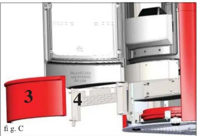
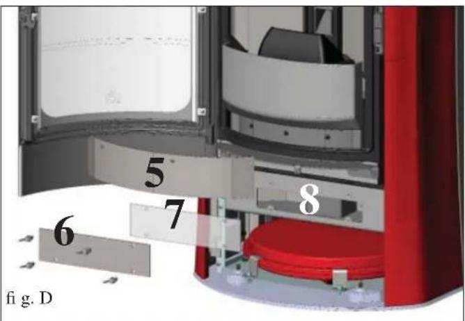
INCONVENIENTS POSSIBLES
natural_image
Black industrial vacuum cleaner with attached hose and control panel (no visible text or symbols)Bidon pour aspirer
INFORMACIÓN GENERAL
natural_image
Close-up of a mechanical component with wires and connectors, no visible text or symbolsINFORMACIÓN GENERAL
LA TERMOESTUFA SE FABRICA EN SEIS VARIANTES ESTÉTICAS
natural_image
3D cutaway view of a red and gray electronic device showing internal components and ventilation (no text or symbols)natural_image
Cross-sectional diagram of a portable air conditioner unit with labeled component C, showing internal structure and housing (no text or symbols beyond labels)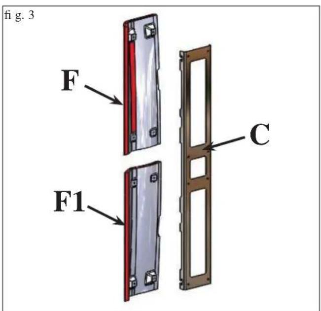
natural_image
3D rendering of a cylindrical industrial device with red and silver casing, showing internal components and ventilation ducts (no text or symbols)Fig. 4
natural_image
3D model of a curved mechanical component with red and black sections, marked with 'H' and two small pins (no text or symbols on the object itself)Fig. 7
natural_image
Illustration of a modern electric heater with red and black casing (no text or symbols)natural_image
Illustration of a red portable toaster with open lid and ventilation grille (no text or symbols)fig. 2
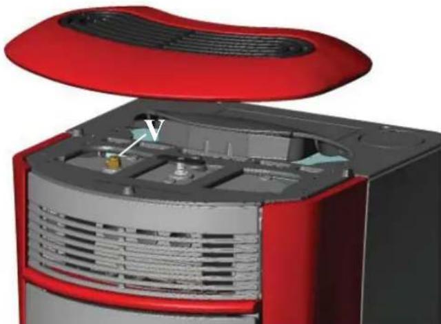
natural_image
3D cutaway view of a red and black electronic device showing internal components (no text or symbols visible)Atención:
line
| Q | H | H max | Hs | H min | |------|-------|-------|------|-------| | 0 | High | High | High | High | | 100 | Low | Low | Low | Low |natural_image
Circular indicator dial with red center and green ring, no visible text or symbolsnatural_image
3D cutaway view of a red and gray electronic device showing internal components and ventilation (no text or symbols)fig.B
MANUTENCIÓN
MANTENIMIENTO ESTACIONAL (a cargo del distribuidor)
natural_image
3D mechanical component with a black housing and mounting bracket, shown in a close-up view (no text or symbols visible)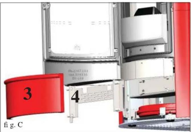
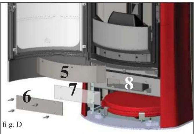
POSIBLES INCONVENIENTES
natural_image
Black industrial vacuum cleaner with attached hose and control panel (no visible text or symbols)ALLGEMEINE INFORMATIONEN
• ELEKTROAPPARATE
natural_image
Close-up of a mechanical component with wires and connectors (no visible text or symbols)ALLGEMEINE INFORMATIONEN
natural_image
3D rendering of a red and gray electronic device with ventilation grilles and a lid open, labeled Abb. 2 (no text or symbols on the device itself)flowchart
graph LR
    A["AL"] --> B["Component: TA"]
    B --> C["Component: VST"]
    C --> D["S"]
    D --> E["VST"]
    E --> F["Component: VST"]
    F --> G["S"]
    G --> H["Component: VST"]
    H --> I["S"]
    I --> J["Component: VST"]
    J --> K["S"]
    K --> L["Component: VST"]
    L --> M["S"]
    M --> N["Component: VST"]
    N --> O["S"]
    O --> P["Component: VST"]
    P --> Q["S"]
    Q --> R["Component: VST"]
    R --> S["S"]
    S --> T["Component: VST"]
    T --> U["S"]
    U --> V["Component: VST"]
    V --> W["S"]
    W --> X["Component: VST"]
    X --> Y["S"]
    Y --> Z["Component: VST"]
    Z --> AA["S"]
    AA --> AB["Component: VST"]
    AB --> AC["S"]
    AC --> AD["Component: VST"]
    AD --> AE["S"]
    AE --> AF["Component: VST"]
    AF --> AG["S"]
    AG --> AH["Component: VST"]
    AH --> AI["S"]
    AI --> AJ["Component: VST"]
    AJ --> AK["S"]
    AK --> AL["Component: VST"]
    AL --> AM["S"]
    AM --> AN["Component: VST"]
    AN --> AO["S"]
    AO --> AP["Component: VST"]
    AP --> AQ["S"]
    AQ --> AR["Component: VST"]
    AR --> AS["S"]
    AS --> AT["Component: VST"]
    AT --> AU["S"]
    AU --> AV["Component: VST"]
    AV --> AW["S"]
    AW --> AX["Component: VST"]
    AX --> AY["S"]
    AY --> AZ["Component: VST"]
    AZ --> BA["S"]
    BA --> BB["Component: VST"]
    BB --> BC["S"]
    BC --> BD["Component: VST"]
    BD --> BE["S"]
    BE --> BF["Component: VST"]
    BF --> BG["S"]
    BG --> BH["Component: VST"]
    BH --> BI["S"]
    BI --> BJ["Component: VST"]
    BJ --> BK["S"]
    BK --> BL["Component: VST"]
    BL --> BM["S"]
    BM --> BN["Component: VST"]
    BN --> BO["S"]
    BO --> BP["Component: VST"]
    BP --> BQ["S"]
    BQ --> BR["Component: VST"]
    BR --> BS["S"]
    BS --> BT["Component: VST"]
    BT --> BU["S"]
    BU --> BV["Component: VST"]
    BV --> BW["S"]
    BW --> BX["Component: VST"]
    BX --> BY["S"]
    BY --> BZ["Component: VST"]
    BZ --> CA["S"]
    CA --> CB["Component: VST"]
    CB --> CC["S"]
    CC --> CD["S"]
    CD --> CE["Component: VST"]
    CE --> CF["S"]
    CF --> CG["Component: VST"]
    CG --> CH["S"]
    CH --> CI["Component: VST"]
    CI --> CJ["Component: VST"]
LEGENDE
AF: Kaltwasser
Abb. 12
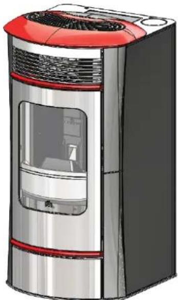
natural_image
Illustration of a modern electric heater with red and black casing (no text or symbols)natural_image
Illustration of a red electric heater with its lid open, showing airflow or ventilation system (no text or symbols)Abb. 2
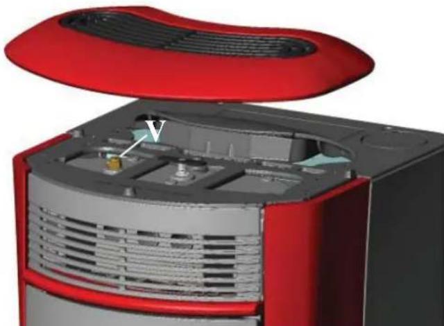
natural_image
3D cutaway view of a red and black electronic device showing internal components (no text or symbols visible)Achtung:
natural_image
Close-up of a black handheld electronic device with a digital display showing '25V' and control buttons (no readable text beyond symbols)
natural_image
3D cutaway view of a red and gray electronic device showing internal components and ventilation (no text or symbols)Abb. B
WARTUNG
natural_image
Exterior view of a mechanical assembly or enclosure with a black component and red vertical panel (no visible text or symbols)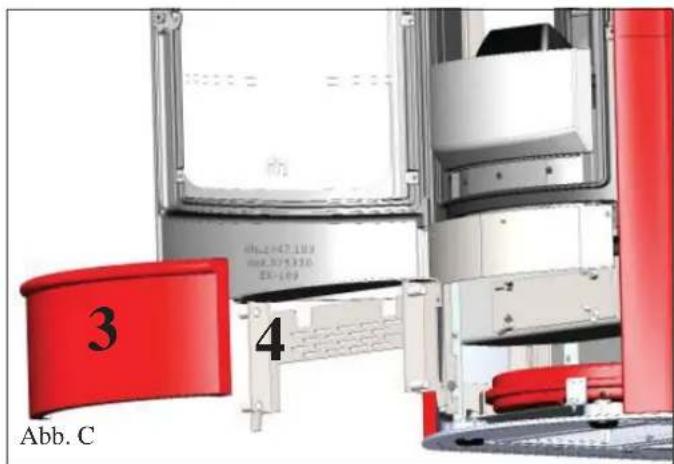
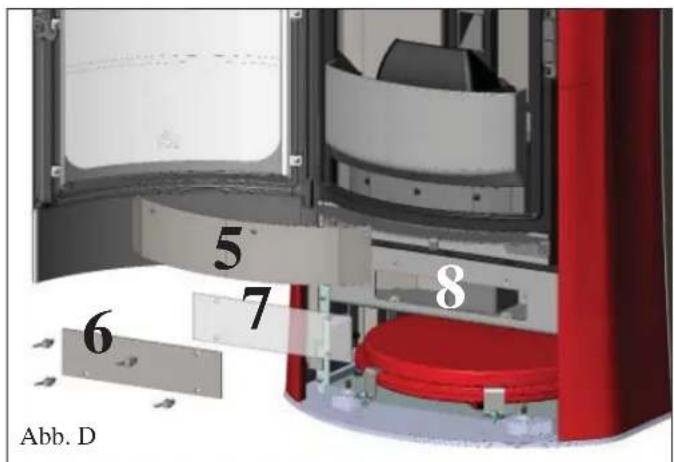
MÖGLICHE PROBLEME
natural_image
Black and white photo of a vacuum cleaner with attached hose and control panel (no visible text or symbols)ALGEMENE INFORMATIE
• ELEKTRONISCHE APPARATEN
natural_image
Close-up of a mechanical component with wires and connectors (no visible text or symbols)ALGEMENE INFORMATIE
DE THERMOKACHEL IS BESCHIKBAAR IN ZES VERSCHILLENDE VARIANTEN:
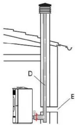
natural_image
3D cutaway view of a red and gray electronic device showing internal components and ventilation (no text or symbols)natural_image
Cross-sectional diagram of a device with labeled parts D and G, showing internal components and no readable text or symbols.Afb. 6
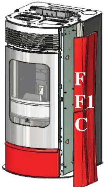
natural_image
3D rendering of a cylindrical industrial device with red and silver casing, showing internal components and no visible text or symbols.Afb. 4
natural_image
Illustration of a modern electric heater with red and black casing (no text or symbols)2) VERSIE MET ZIJPANELEN IN STAAL EN PROFIELEN EN BOVENPANEEL IN KERA-MIEK
Afb. 10
natural_image
Illustration of a red electric heater with its vented grille and open lid (no text or symbols)Afb. 2
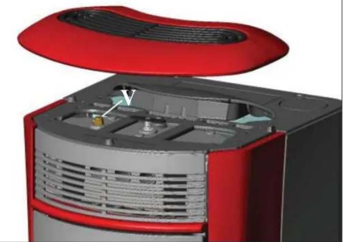
natural_image
3D cutaway view of a red and gray electronic device showing internal components (no text or symbols visible)Let Op:
natural_image
Close-up of a black handheld electronic device with a green display screen showing '254' and control buttons (A, M, +, -), no readable text or symbols beyond the display.
DRUK DE TOETS NOOIT MEERDERE KEREN IN
Systeem pelletreserve
natural_image
Circular device with red center and green ring, no visible text or symbolsnatural_image
3D cutaway view of a red and gray electronic device showing internal components and ventilation (no text or symbols)Afb. B
ONDERHOUD
SEIZOENSGEBONDEN ONDERHOUD (door de dealer)
natural_image
3D mechanical assembly diagram showing a cylindrical component mounted inside a vertical frame with red and white components (no text or symbols)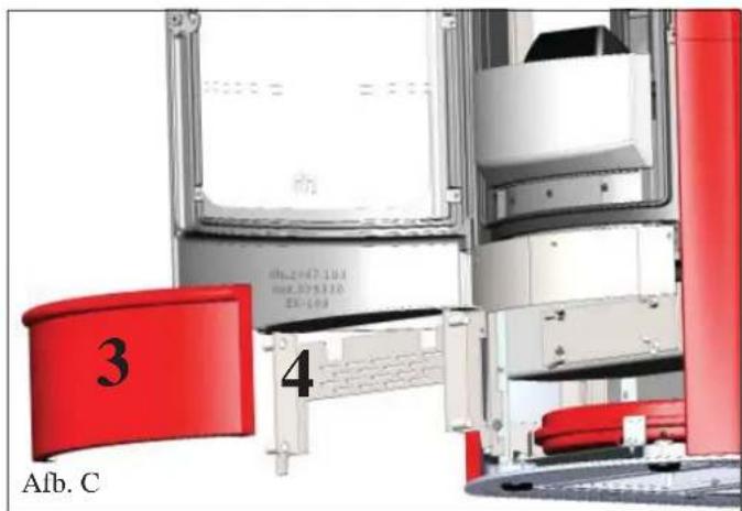
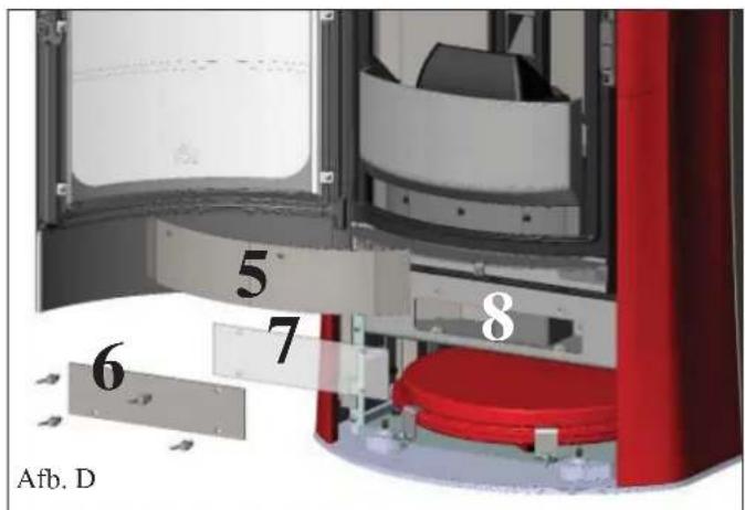
MOGELIJKE STORINGEN
natural_image
Black and white photo of a vacuum cleaner with attached hose and control panel (no visible text or symbols)GENERELLE OPLYSNINGER
• ELEKTRONISKE APPARATER
natural_image
Close-up of a mechanical component with wires and connectors (no visible text or symbols)GENERELLE OPLYSNINGER
BRÄNDEOVNEN NEA FÅS I TO MODELLER:
- mørkegråt stål med indsatser og top i cremefarvet keramik
- mørkegråt stål med indsatser og top i rød keramik
- mørkegråt stål med indsatser og top i grå keramik
- cremefarvet keramik
- rød keramik
- pergamentfarvet keramik
FORSIDE
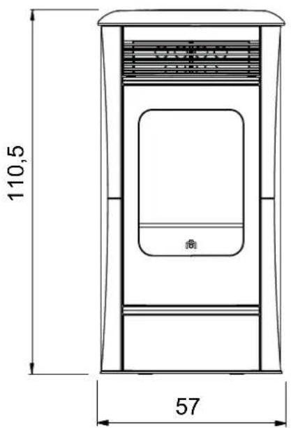
BAGSIDE
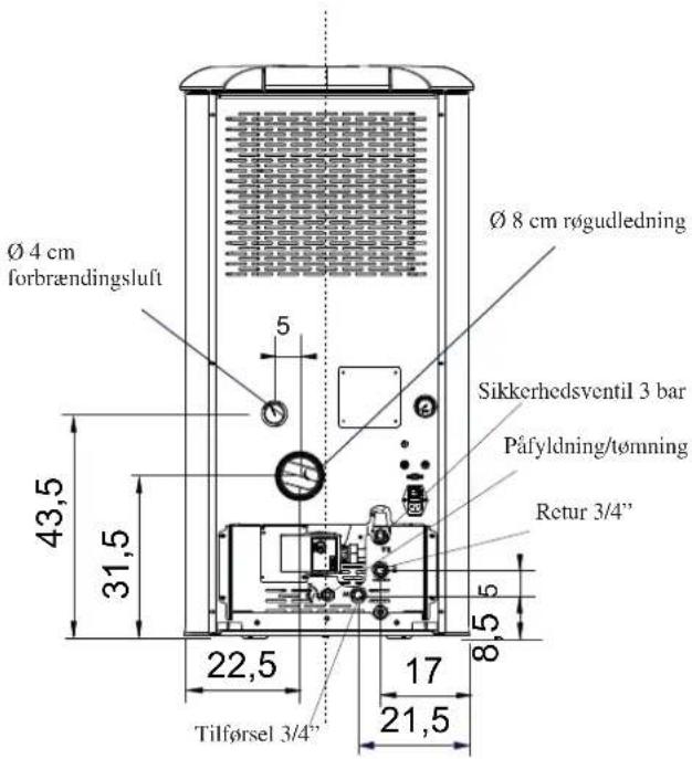
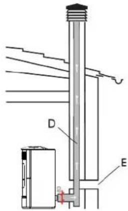
natural_image
3D cutaway view of a red and gray electronic device showing internal components and ventilation (no text or symbols)natural_image
Cross-sectional diagram of a device showing internal components and labeled parts (no text or symbols beyond labels)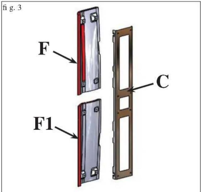
1) VERSION ME SIDER OG TOP I KERAMIK
natural_image
3D model of a curved mechanical component with red and black sections, marked with 'H' and two small bolts (no text or symbols on the object itself)Fig. 7 Løsn de 2 medfølgende rillede M4-tapper på bagsiden af det øvre element i keramik (H).
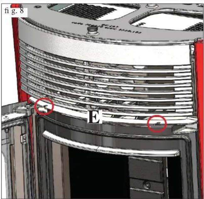
fig.12
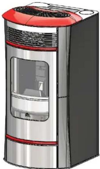
natural_image
Illustration of a modern electric heater with red and black casing (no text or symbols)2) VERSION MED SIDER I STÅL SAMT PROFILER OG TOP I KERAMIK
Fig. 10
Brændeovnen leveres (fi g. 1) med metalsiderne (A-B) og de nederste/øverste metalfronte (D - E) allerede monterede. Nedenstående dele er derimod pakket separat.
PELLETPÄFYLDNING I BEHOLDEREN
natural_image
Illustration of a red electric heater with its lid open, showing its grille and vent (no text or symbols)fig. 2
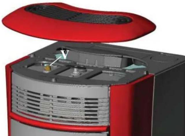
natural_image
3D cutaway view of a red and black electronic device showing internal components (no text or symbols visible)Giv agt:
natural_image
Black handheld electronic device with a digital display showing '254' and control buttons (no readable text beyond basic symbols)
Pellet reservesystem
natural_image
3D cutaway view of a red and gray electronic device showing internal components and ventilation (no text or symbols)fig. B
VEDLIGEHOLDELSE
natural_image
3D mechanical component with a black housing and mounting bracket, shown in a technical view (no text or symbols visible)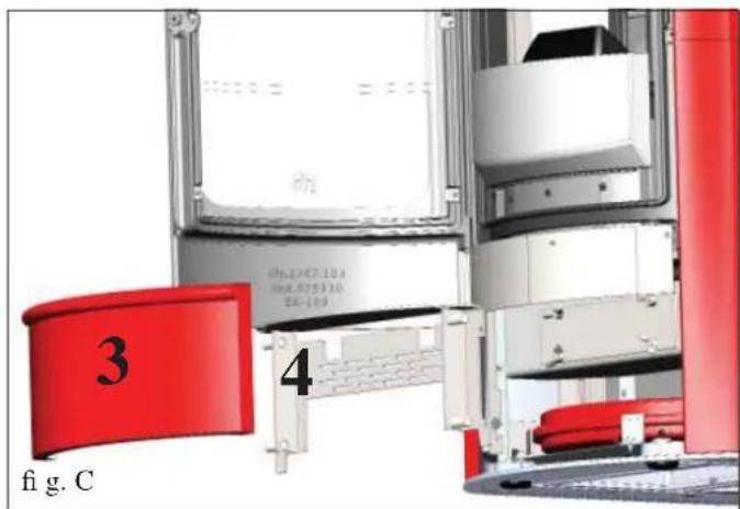
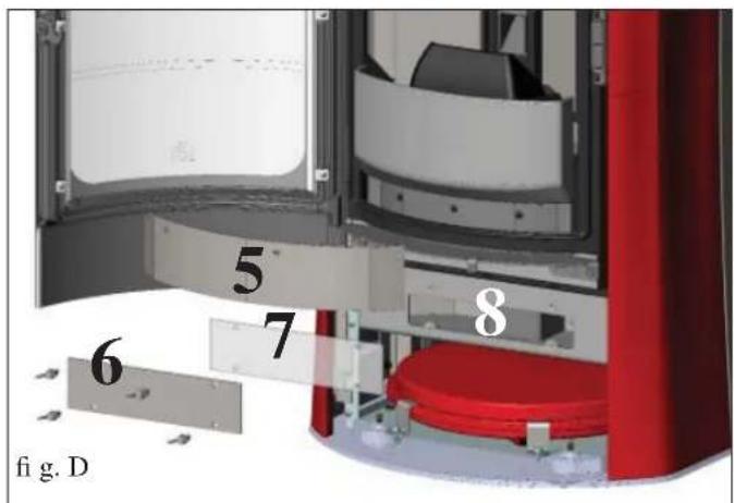
MULIGE ULEMPER
natural_image
Black and white photo of a vacuum cleaner with attached hose and control panel (no visible text or symbols)INFORMAÇÕES GERAIS
• APARELHAGEM ELECTRÓNICA
natural_image
Close-up of a mechanical component with wires and a metallic housing, marked with asterisks (no readable text or symbols)INFORMAÇÕES GERAIS
natural_image
3D cutaway view of a red and gray electronic device showing internal components and ventilation (no text or symbols)natural_image
Cross-sectional diagram of a portable air conditioner unit with labeled component C, showing internal structure and housing (no text or symbols beyond labels)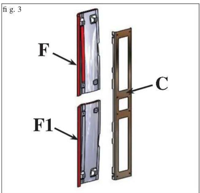
1) VERSÃO COM LATERAIS E TOPO EM CERÂMICA
Fig. 1
natural_image
3D model of a curved mechanical component with red and black sections, marked with 'H' and two small pins (no text or symbols on the object itself)natural_image
Illustration of a modern electric heater with red and black casing (no text or symbols)2) VERSÃO COM LATERAIS EM AÇO E PERFIS E TOPO EM CERÂMICA
Fig. 10
INSTRUÇÕES PARA O USO
natural_image
Illustration of a red electric heater with its hood open, showing internal airflow patterns (no text or symbols)fig. 2
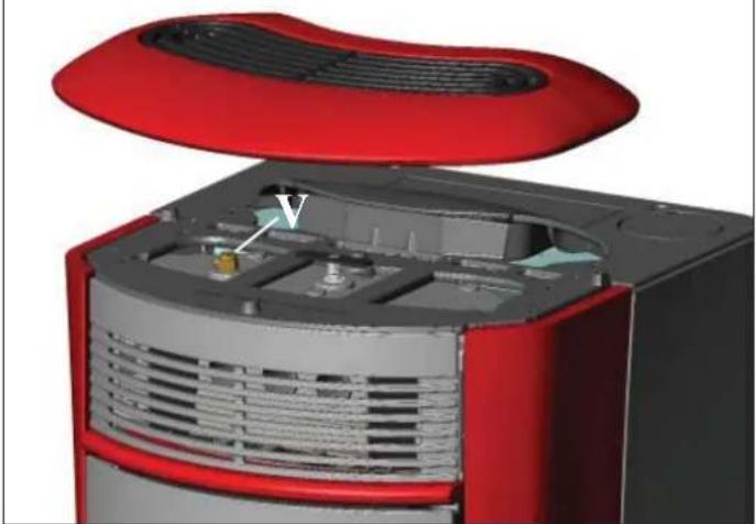
natural_image
3D cutaway view of a red and gray electronic device showing internal components (no text or symbols visible)Atenção:
natural_image
Close-up of a black handheld electronic device with a green display screen showing the number 254 (no readable text or symbols beyond the display)
- ícone intermitente: controlo remoto procurando a rede
INSTRUÇÕES PARA O USO
natural_image
3D cutaway view of a red and gray electronic device showing internal components and ventilation (no text or symbols)fig.B
MANUTENÇÃO
natural_image
3D mechanical component with a black housing and mounting bracket, shown in a technical view (no text or symbols visible)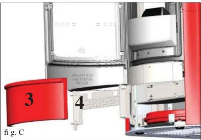
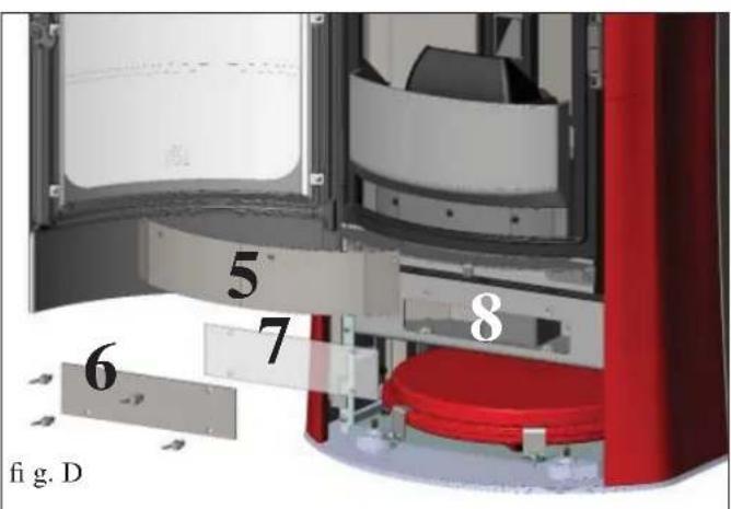
POSSÍVEIS INCONVENIENTES
natural_image
Black and white photo of a portable vacuum cleaner with attached hose and control panel (no visible text or symbols)Provozní režim
natural_image
Close-up of a mechanical component with wires and connectors, no visible text or symbols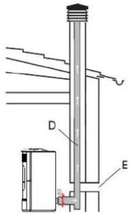
natural_image
3D cutaway view of a red and gray electronic device showing internal components and ventilation (no text or symbols)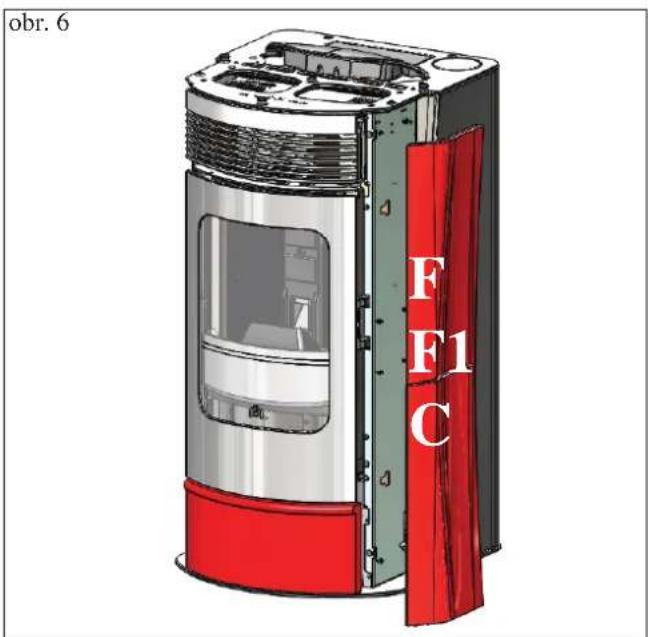
Obr. 4
Obr. 9
natural_image
Illustration of a modern electric heater with red and silver casing (no text or symbols)2) VERZE OCELOVÝMI BOKY A HORNÍ KERA- MICKOU DESKOU
Obr. 10
natural_image
Illustration of a red electric heater with its hood open, showing internal ventilation grilles and a door (no text or symbols)obr. 2

natural_image
3D cutaway view of a red and gray electronic device showing internal components (no text or symbols visible)Pozor:
natural_image
Black handheld electronic device with a green screen displaying '25x' and control buttons (no readable text beyond symbols)
SEŘÍZENÍ TEPLOTY NA VSTUPU:
natural_image
Circular gauge or dial with red center and green ring, no visible text or symbolsnatural_image
3D cutaway view of a red and silver electronic device showing internal components and ventilation (no text or symbols)obr. B
ÚDRŽBA
natural_image
3D rendering of a mechanical component with a black housing and red vertical panel, no visible text or symbols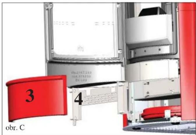
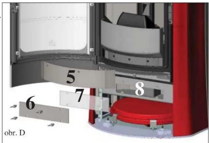
PORADCE PŘI MOŽNÝCH POTÍŽÍCH
natural_image
Black and white photo of a vacuum cleaner with attached hose and control panel (no visible text or symbols)Vysavač popela
- 1) VERSIONE CON FIANCHI E TOP IN CERAMICA
- Fig. 1
- 2) VERSIONE CON FIANCHI IN ACCIAIO E PROFILI E TOP IN CERAMICA
- Fig. 10
- Attenzione:
- MANUTENZIONE
- CONSIGLI PER POSSIBILI INCONVENIENTI
- Dear Sir/Madam
- NOTE
- - Commissioning/ testing
- SAFETY INFORMATION
- GENERAL INFORMATION
- Operating modes
- • ELECTRONIC CIRCUIT BOARD
- SERIAL PORT
- BACKUP BATTERY
- THE IDROSALLYIS PRODUCED IN SIX DIFFERENT FINISHES:
- N.B.
- • COMPONENTS - SAFETY AND DETECTION DEVICES
- Smoke thermocouple
- Flow sensor
- Feed Screw safety thermostat
- Water temperature detector
- Water overheating safety thermostat
- Overpressure valve 3 bar
- Electric coil
- Smoke extractor
- Vacuum gauge (electronic pressure sensor):
- Tank safety thermostat:
- Pump (electronic circulator - see page. 53)
- Closed expansion tank
- Manometer
- Drain tap
- Venting valve:
- N.B.:
- Declaration of performance
- • CERTIFICATIONS AND BENEFITS \*
- INSTALLATION
- GENERAL NOTES
- VERIFY COMPATIBILITY WITH OTHER DEVICES
- VERIFY THE POWER SUPPLY
- CONNECTION (the plug must be accessible)
- AIR INLET (to be mandatorily implemented)
- POSITIONING AND DISTANCES FOR FIRE SAFETY
- SMOKE OUTLET
- CHIMNEY POT
- TYPICAL EXAMPLES
- PLUMBING CONNECTION
- • HYDRAULIC CONNECTIONS:
- HEATING SYSTEM WITH THE THERMO STOVE AS THE ONLY HEAT SOURCE
- LEGEND
- ACCESSORIES:
- COVERING INSTALLATION
- 1) VERSION WITH CERAMIC SIDES AND TOP
- Tofi t proceed as follows:
- 2) VERSION WITH STEEL SIDES AND CERA- MIC PROFILES AND TOP
- Fig. 11
- Fig. 12
- INSTRUCTIONS FOR USE
- 1st ignition/test by the Edilkamin authorised Dealer
- The presence of a tank within the boiler-stove does NOT guarantee appropriate protection from thermal expansion occurring in the whole system.
- FILLING THE PELLET HOPPER
- ATTENTION:
- NOTE regarding the fuel.
- REMOTE CONTROL
- Key to buttons and display:
- DO NOT PRESS THE BUTTON MORE THAN ONCE
- VENTILATION ADJUSTMENT:
- Filling the cochlea.
- Automatic igniting.
- Manual igniting.
- OUTPUT TEMPERATURE ADJUSTMENT:
- ENVIRONMENT TEMPERATURE ADJUSTMENT:
- Turning off
- OPERATIONS THAT CAN ONLY BE CARRIED OUT BY REMOTE CONTROL
- Clock regulation
- Weekly timer
- Notes on flame variability
- RESERVE WARNING
- Pellet reserve system
- EMERGENCY BUTTON
- THE ELECTRONIC CIRCULATOR
- (low-consumption pump)
- Electronic control of operation:
- a) Control mode p - c
- b) Control mode p - v
- c) Venting procedure
- MAINTENANCE
- DAILY MAINTENANCE
- AT LEAST ONCE A DAY ACTION THE CLEANING BRUSHES OF THE EXCHANGERS (\*), EVEN WHILE THE STOVE IS LIT, USING THE GLOVE PROVIDED:
- WEEKLY MAINTENANCE
- SEAS ONAL MAINTE NANCE
- ATTENTION !!!
- CLEANING THE SMOKE CHANNEL
- POSSIBLE TROUBLESHOOTING
- INDICATION OF POSSIBLE CAUSES OF MALFUNCTION AND INDICATIONS AND REMEDIES:
- 1) Signalling: H2O PTC\_FAULT
- NOTE 1
- NOTE 2
- NOTE 3
- IMPORTANT!!!
- FAQ
- 1) What do I need to prepare in order to install the boiler-stove?
- 2) Can the boiler-stove work without water?
- 3) Does the boiler-stove generate hot air?
- 4) Can I connect the inlet and outlet of the boiler-stove directly to a radiator?
- 5) Do boiler-stove also supply hot sanitary water?
- 6) Can I discharge the smoke from the boiler-stoves along the wall?
- 7) Do I need an air inlet in the room where it is installed?
- 8) What settings are required on the boiler-stove display?
- 9) How often do I need to clean the combustion chamber?
- 10) Do I need to vacuum the pellet hopper?
- 11) Can I burn other fuel apart from pellets?
- 12) Can I ignite the boiler-stove by sending an SMS?
- CHECK LIST
- To be integrated with a complete reading of the technical specifications
- Positioning and installation
- Use
- OPTIONAL
- TELEP HONE COMBINER FOR RE MOTE IGNITION
- CLEANING ACCESSORIES
- INFORMATION FOR USERS
- NOTES
- DATE AND STAMP INSTALLER
- TABLE DES MATIÈRES
- INFORMATIONS GÉNÉRALES
- • APPAREILS ÉLECTRONIQUES
- LE THERMOPOÊLE EST DISPONIBLE DANS SIX VARIANTES ESTHÉTIQUES :
- 1) VERSION AVEC CÔTÉS ET TOP EN CÉRAMIQUE
- ENTRETIEN
- ENTRET IEN SA ISONNIER (par le revendeur)
- INCONVENIENTS POSSIBLES
- INFORMACIÓN GENERAL
- LA TERMOESTUFA SE FABRICA EN SEIS VARIANTES ESTÉTICAS
- Atención:
- MANUTENCIÓN
- MANTENIMIENTO ESTACIONAL (a cargo del distribuidor)
- POSIBLES INCONVENIENTES
- ALLGEMEINE INFORMATIONEN
- • ELEKTROAPPARATE
- LEGENDE
- Achtung:
- WARTUNG
- MÖGLICHE PROBLEME
- ALGEMENE INFORMATIE
- • ELEKTRONISCHE APPARATEN
- DE THERMOKACHEL IS BESCHIKBAAR IN ZES VERSCHILLENDE VARIANTEN:
- Afb. 4
- 2) VERSIE MET ZIJPANELEN IN STAAL EN PROFIELEN EN BOVENPANEEL IN KERA-MIEK
- Afb. 10
- DRUK DE TOETS NOOIT MEERDERE KEREN IN
- Systeem pelletreserve
- ONDERHOUD
- SEIZOENSGEBONDEN ONDERHOUD (door de dealer)
- MOGELIJKE STORINGEN
- GENERELLE OPLYSNINGER
- • ELEKTRONISKE APPARATER
- BRÄNDEOVNEN NEA FÅS I TO MODELLER:
- 1) VERSION ME SIDER OG TOP I KERAMIK
- 2) VERSION MED SIDER I STÅL SAMT PROFILER OG TOP I KERAMIK
- PELLETPÄFYLDNING I BEHOLDEREN
- Giv agt:
- Pellet reservesystem
- VEDLIGEHOLDELSE
- MULIGE ULEMPER
- INFORMAÇÕES GERAIS
- • APARELHAGEM ELECTRÓNICA
- 1) VERSÃO COM LATERAIS E TOPO EM CERÂMICA
- 2) VERSÃO COM LATERAIS EM AÇO E PERFIS E TOPO EM CERÂMICA
- INSTRUÇÕES PARA O USO
- Atenção:
- MANUTENÇÃO
- POSSÍVEIS INCONVENIENTES
- Provozní režim
- Obr. 4
- 2) VERZE OCELOVÝMI BOKY A HORNÍ KERA- MICKOU DESKOU
- Obr. 10
- Pozor:
- SEŘÍZENÍ TEPLOTY NA VSTUPU:
- ÚDRŽBA
- PORADCE PŘI MOŽNÝCH POTÍŽÍCH
Brand : EDILKAMIN
Model : IDROSALLY
Category : Central heating boiler