VDV500-920 - Measuring equipment Klein Tools - Free user manual and instructions
Find the device manual for free VDV500-920 Klein Tools in PDF.

| Product Type | Toner Generator Kit (Toner-Pro VDV500-163) and Probe (Probe-Pro VDV500-223) |
| Brand | Klein Tools |
| Model | VDV500-920 |
| Dimensions (Toner-Pro) | 118 mm × 64 mm × 28 mm |
| Dimensions (Probe-Pro) | 49 mm × 253 mm × 34 mm |
| Weight (Toner-Pro with batteries) | 150 g |
| Weight (Probe-Pro with batteries) | 195 g |
| Power Supply | 4 AAA 1.5 V alkaline batteries per device |
| Battery Life (Active) | 20 hours |
| Battery Life (Standby/Storage) | 3 years |
| Auto Shutoff (Toner-Pro) | After 60 minutes of inactivity |
| Auto Shutoff (Probe-Pro) | After 15 minutes of inactivity |
| Operating Temperature Range | 0 °C to 50 °C (Toner) / -10 °C to 50 °C (Probe) |
| Available Tones | Analog: 1000 Hz, 1500 Hz, alternating 1000/1500 Hz; Digital |
| Main Functions | Locating paired or unpaired wires, continuity test (< 10 kΩ), polarity test, pin-to-pin RJ45 mapping, RJ11/RJ12/RJ45 testing |
| Overvoltage Protection (Test Mode) | 60 V |
| Overvoltage Protection (Tone Mode) | 20 V via external 600 Ω source |
| LED Indicators | Continuity (green/red), normal/reversed polarity, wiring diagram 1-8, shield, battery level |
| 60 Hz Filter (Probe-Pro) | Yes, to reduce interference from devices operating at 60 Hz |
| Included Accessories | Toner-Pro VDV500-163, Probe-Pro VDV500-223, ABN test leads, test cords, wrist strap |
| Replacement Parts Available | Replacement inductive tip (VDV999-070) |
| Maintenance | Clean with a lint-free cloth, do not use abrasive cleaners or solvents |
| Safety | Do not use on live circuits, do not open the case except for battery compartment |
| Warranty | See www.kleintools.com/warranty |
| Country of Origin | Not specified, US brand |
Frequently Asked Questions - VDV500-920 Klein Tools
User questions about VDV500-920 Klein Tools
0 question about this device. Answer the ones you know or ask your own.
Ask a new question about this device
Download the instructions for your Measuring equipment in PDF format for free! Find your manual VDV500-920 - Klein Tools and take your electronic device back in hand. On this page are published all the documents necessary for the use of your device. VDV500-920 by Klein Tools.
USER MANUAL VDV500-920 Klein Tools
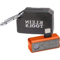
The Klein Tools VDV500-163 Digital Toner-Pro is a professional-series analog and digital tone generator for wire identification, wire tracing and wire pair identification. It features several tone frequencies and strong power output for tracing wires.
- Operating Altitude: 6562 ft. (2000 m) maximum
- Relative Humidity: 10% – 90% non-condensing
- Operating Temp: 32° to 122° F (0° to 50°C)
• Storage Temp -4° to 140°F (-20° to 60°C)
• Dimensions: 4.65" × 2.52" × 1.10" (118 × 64 × 28 mm)
• Weight: 5.29 oz. (150 g) including batteries - Battery Type: 4 × 1.5V AAA Alkaline
• Battery Life: Active: 20 hours
Standby/Storage: 3 years
• Auto-Power Off: After 60 minutes of inactivity
• Analog Tones: Constant: 1000Hz, 1500Hz
Alternating: 1000Hz/1500Hz - Tone Power: 8dBm
• Continuity Indication: Less than 10kΩ
• Voltage Protection: Test Mode: 60V
Tone Mode: 20V through external 600Ω
Specifications subject to change.
FEATURE DETAILS - VDV500-163 DIGITAL TONER-PRO
text_image
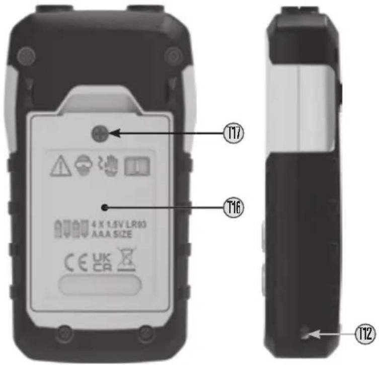
T17 T16 4 X 1.5V LR93 AAA SIZE CE UK CA T12| SYMBOLS - VDV500-163 DIGITAL TONER-PRO | |||
| Warning or Cautior | CE | Conformité Européenne: Conforms with European Economic Area directives | |
| Always wear approved eye protection | UKCA | UKCA: UK Conformity Assessment | |
| Do NOT use or energized circuits | WFFF: Electronics disposa | ||
| Read instructions | |||
FEATURE DETAILS - VDV500-163 DIGITAL TONER-PRO
text_image
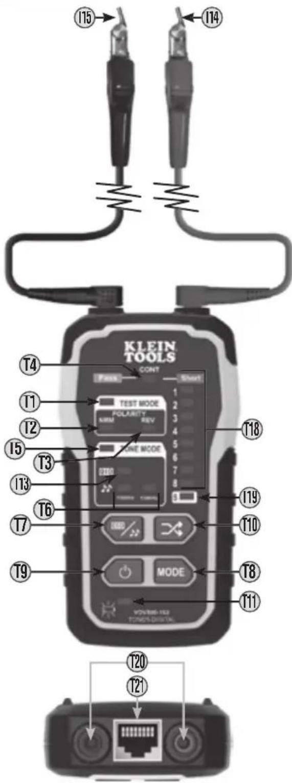
KLEIN TOOLS CONT TEST MODE POLARITY REF LINE MODE MODE VOLUME-102 FONOS-DISTRA T4 T1 T2 T5 T3 T13 T6 T7 T9 T15 T14 T18 T19 T10 T8 T11 T20 T21T1 TEST MODE Indicator
T2 "NRM" (Normal) Polarity Indicator
T3 "REV" (Reverse) Polarity Indicator
T4 "CONT" (Continuity) Indicator
T5 TONE MODE Indicator
T6 Analog Tone Frequency Indicators
T7 Digital/Analog Tone Button
T8 Mode button
T9 Power On/Off Buttor
T10 Pin/Pair Selection Buttor
T11 Battery Status Indicator
T12 Lanyard Slot
T13 Digital Tone Indicator
T14 Red ABN (Anglec Bed-of-Nails) Test Clip
T15 Black ABN (Angled Bed-of-Nails) Test Clip
T16 Battery Cover
T17 Battery Cover Screw
T18 Wire Map Indicator
T19 Shield Indicator
T20 Test Lead Inputs
T21 RJ45 Por
⚠️ WARNINGS
To ensure safe operations and service of the instruments, follow these instructions. Failure to observe these warnings can result in fire, electric shock, severe injury or death.
- The Digital Toner-Pro, test leads, and Digital Probe-Pro, are designed for use on extra-low voltage cabling systems (less than 60V) for testing when NOT energized.
- The maximum voltage across ABN Test Clips of the Digital Toner-Pro is 60V in Tes mode, and 20V in Continuity mode. Connecting the Digital Probe-Pro to live mains AC power may damage it and pose a safety hazard for the user
• DO NOT use instruments if they are wet, as it could pose a shock hazard
• DO NOT use instruments if they are damaged in any way - Turn off instruments and disconnect all ABN Test Clips before attempting to replace batteries
• The battery door must be in place and secure before you operate the instrument. - DO NOT open the case, other than the battery compartment.
ENGLISH
GENERAL SPECIFICATIONS - VDV500-223 DIGITAL PROBE-PRO
The Klein Tools VDV500-223 Digital Probe-Pro is a professional-series digital and analog tone tracer, featuring an inductive probe with speaker for amplification, and LED light for use in dark spaces. It also features a headphone jack for use in extreme noise environments.
- Operating Altitude: 6562 ft. (2000 m) maximum
- Relative Humidity: 10% – 90% non-condensing
- Operating Temp: 14° to 122°F (-10° to 50°C)
• Storage Temp: -4^ to 140^ F ( -20^ to 60^ C) - Dimensions: 1.92" × 9.96" × 1.32" (49 × 253 × 34 mm)
• Weight: 6.88 oz. (195 g) including batteries - Battery Type: 4 × 1.5V AAA Alkaline
- Battery Life: Active: 20 hours
Standby/Storage 3 years
• Auto-Power Off: After 15 minutes of inactivity
Specifications subject to change.
FEATURE DETAILS - VDV500-223 DIGITAL PROBE-PRO
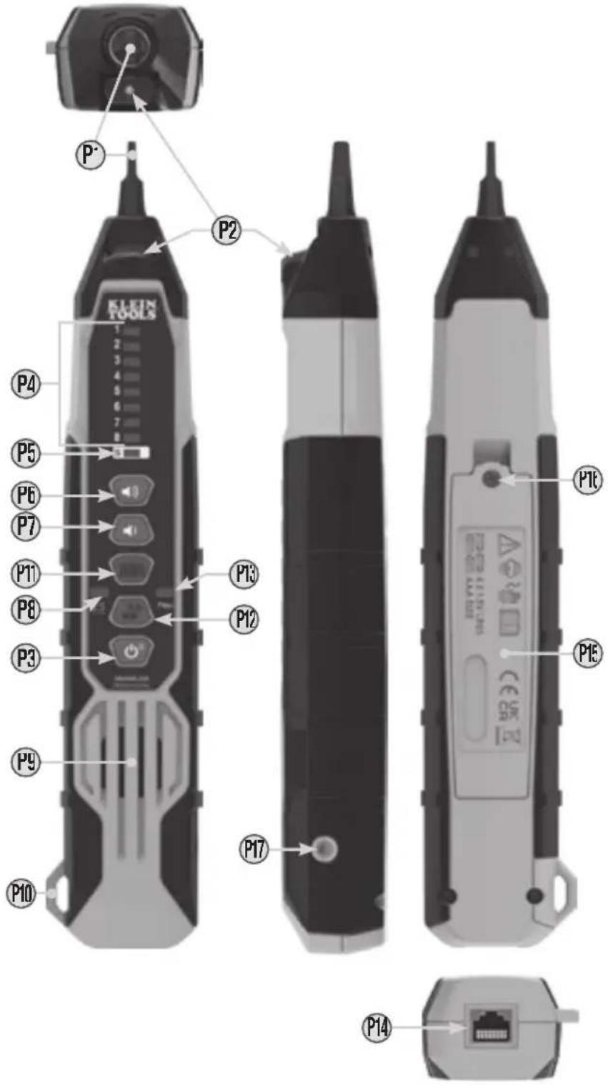
P1 Replaceable Inductive Polymer Tip (VDV999-070
P2 Worklight
P3 Power/Worklight On/Off Button
P4 Wire Map Indicators*
P5 Shield Indicator'
* P4 + P5 together constitute Signal Strength Indicator Bars
P6 Volume Increase Button
P7 Volume Decrease Button
P8 Battery Status Indicator
P9 Speakei
P10 Lanyard Slot
P11 Digital Toning Mode Button
P12 Analog Toning Mode / 60Hz Filter On/Off Button
P13 Filter Indicator
P14 RJ45 Port
P15 Battery Cover
P16 Battery Cover Screw (#2 Phillips)
P17 3.5mm Headphone Jack*
*△ CAUTION: Excessive volume can cause permanent hearing damage. Use as low a volume as possible.
| SYMBOLS - VDV500-223 DIGITAL PROBE-PRO | |||
| Warning or Cautior | Conformité Européenne: Conforms with European Economic Area directives | ||
| Always wear approved eye protector | UKCA: UK Conformity Assessment | ||
| Do NOT use or energized circuits | WFFF: Electronics disposa | ||
| Read instructions | |||
FEATURE DETAILS - VDV500-223 DIGITAL PROBE-PRO
To ensure safe operations and service of the instrument, follow these instructions. Failure to observe these warnings can result in fire, electric shock, severe injury or death.
- The Digital Probe-Pro is designed for use on extra-low voltage cabling systems (less than 60V) for testing when NOI energized.
• DO NOT use instrument if wet, as it could pose a shock hazard. - DO NOT use instrument if damaged in any way.
- Turn off instrument before attempting to replace batteries
- The battery door must be in place and secure before you operate the instrument.
- DO NOT open the case, other than the battery compartment.
OPERATING INSTRUCTIONS
READ ALL INSTRUCTIONS BEFORE OPERATING AND RETAIN INSTRUCTIONS FOR FUTURE REFERENCE
TURNING DIGITAL PROBE-PRO AND WORKLIGHT ON/OFF
- Turn the probe on by pressing the Power On/Off Button P3 once
- When the probe is on, press the Power On/Off Button P3 to turn the worklight on/off.
- To turn off the probe, press and hold the Power On/Off Button P: for more than 2 seconds.
TONE MODE
-
Turn Digital Toner-Pro on by pressing the Power On/Off button ⑲
-
The Toner defaults to Digital Tone Mode, with the Digital Tone Indicato ⑪, and Wire Map Indicator ⑪ LEDs 3 and 6 illuminated. The LEDs may be blinking, depending on whether the Toner is connected to a network port
-
Set the tone mode to either digital toning or analog toning by pressing the Digital/Analog Tone Buttor T7 to cycle thru the different options. The Digital Tone Indicator T3, will illuminate when in digital toning mode. One or both Analog Tone Frequency Indicators T6 will illuminate when in analog toning mode. There are three frequencies available to choose from when in analog mode: 1000Hz, 1500Hz, and 1000/1500Hz warble.
NOTE: When performing analog toning via the RJ45 port, the tone can be sent down an individual pin, a pin pair, or to all eight pins simultaneously. To cycle thru the analog tone options, repeatedly press the Pin/Pair Selector Button 10 to select the desired mode. The Wire Map Indicator 18 will illuminate which pin or pin pairs will be toned. When performing digital toning via the RJ45 port, the signal is only sent to pin pair 3-6. Wire Map Indicator LEDs 3 and 6 will blink if toner is connected to an active network port, otherwise LEDs 3 and 6 will remain constantly illuminated.
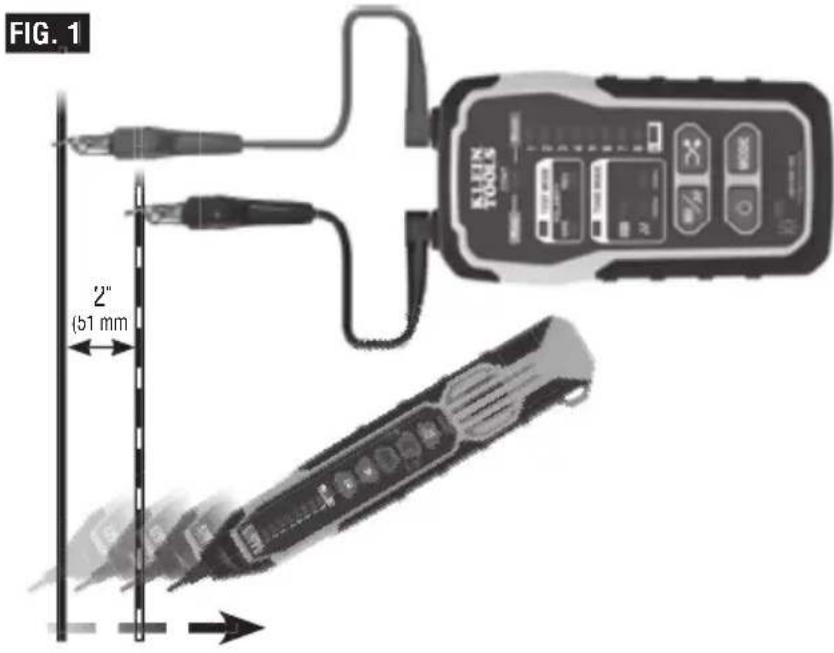
TRACING PAIRED WIRES (FIG. 1)
- Connect the Digital Toner-Pro's ret (14) and black (15) ABN Test Clip leads to their respective Test Lead Inputs (20)
- Connect the red ABN Test Clip T14 to one of the wires of the pair to be traced. Connect the black ABN Test Clip T15 to the other wire to be traced.
- Turn Digital Toner-Pro on by pressing the Power On/Off button 19.
-
The Toner defaults to Digital Tone Mode, with the Digital Tone Indicator ①3, and Wire Map Indicator ①8 LEDs 3 and 6 illuminated. The LEDs may be blinking, depending on whether the Toner is connected to a network port. When performing analog toning, check the "CONT" Indicator ①4. If illuminated green, you may proceed
NOTE: When performing Digital Toning, the "CONT" Indicator ⑭ will not illuminate. -
Select the preferred tone setting using the Digital/Analog Tone Button ⑰
-
Turn the Digital Probe-Pro on by pressing the Power On/Off button P3.
-
At the far end of the cable, spread the wires apart at least 2" (51 mm), if possible.
-
If performing analog toning, first ensure the Digital Toner-Pro is set to analog toning mode. Then ensure the Digital Probe-Pro is set to analog mode by pressing the Analog Mode button Ⓟ12. The Analog Mode Button will illuminate green when in analog mode. If performing digital toning, first ensure the Digital Toner-Pro is set to digital toning mode. Then ensure the Digital Probe Pro is set to digital mode by pressing the Digital Mode Button Ⓟ11. The Digital Mode Button will illuminate blue when in digital mode
-
Use the Digital Probe-Pro to scan the cable's wire pairs. Move the Digital Probe-Pro's tip P1 slowly across the wires (FIG. 1). The Digital Probe-Pro's volume and Signal Strength Indicator bars P4 + P5 will increase as it approaches the toned pair. When the Digital Probe-Pro's volume and Signal Strength Indicator bars are high over the first wire, low in the middle (between) the two wires, and high over the second wire, you have located the pair of wires you are tracing. Use the Volume Increase P6 and Volume Decrease P7 buttons to adjust the volume.
OPERATING INSTRUCTIONS
text_image
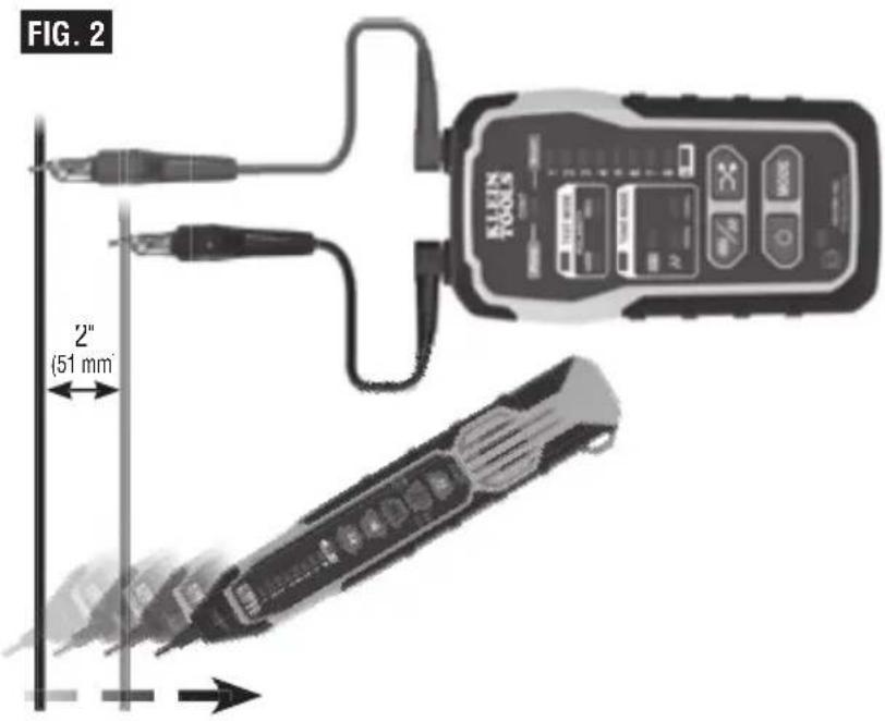
FIG. 1 2" (51 mm)TRACING NON-PAIRED WIRES (FIG. 2)
1 Connect the Digital Toner-Pro's rec (14) and black (15) ABN Test Clip leads to their respective Test Lead Inputs (120)
2. Connect the Digital Toner-Pro's red ABN Test Clip 114 to the wire to be traced.
3. Connect the black ABN Test Clip ⑦5 to another wire in the cable, but preferably not in the same pair (connect to ground, if available). When tracing a shielded cable, connect the red ABN Test Clip to the outer shield, and the black ABN Test Clip to the center conductor or ground.
4. Turn Digital Toner-Pro on by pressing the Power On/Off button 19.
5. The Toner defaults to Digital Tone Mode, with the Digital Tone Indicator ①3, and Wire Map Indicator ①8 LEDs 3 and 6 illuminated. The LEDs may be blinking, depending on whether the Toner is connected to a network port. The "CONT" Indicator ④ illuminates green or red only when in analog mode When performing analog toning, check the "CONT" Indicator ④. If illuminated green, you may proceed
NOTE: When performing Digital Toning, the "CONT" Indicator ⑭ will not illuminate.
6. Turn the Digital Probe-Pro on by pressing the Power On/Off button
7. Select the preferred tone setting using the Digital/Analog Tone Buttor T7.
8. At the far end of the cable, spread the wires at least 2" (51 mm) apart, if possible.
9. If performing analog toning, first ensure the Digital Toner-Pro is set to analog toning mode. Then ensure the Digital Probe-Pro is set to analog mode by pressing the Analog Mode button Ⓟ12. The Analog Mode Button will illuminate green when in analog mode. If performing digital toning, first ensure the Digital Toner-Pro is set to digital toning mode. Then ensure the Digital Probe Pro is set to digital mode by pressing the Digital Mode Button Ⓟ11. The Digital Mode Button will illuminate blue when in digital mode
10. Use the Digital Probe-Pro to scan the cable's wire pairs. Move the Digital Probe Pro's tip (P) slowly across the wires (FIG. 2). The Digital Probe-Pro's volume and Signal Strength Indicator bars (P) + (P) will increase as it approaches the toned pair. When the Digital Probe-Pro's volume and Signal Strength Indicator bars are high over the first wire, low in the middle (between) the two wires, and high over the second wire, you have located the pair of wires you are tracing. Use the Volume Increase (P6) and Volume Decrease (P7) buttons to adjust the volume.
OPERATING INSTRUCTIONS
USING THE 60HZ FILTER
The Digital Probe-Pro has a 60Hz filter to help trace cables/wires when toning near devices running on 60Hz. Press the Analog Toning Mode / 60Hz Filter On/Off Button P12 to turn the 60Hz filter on/off. The Filter Indicator P13 will illuminate when the 60Hz filter is on
NOTE: 60Hz filtering can only be used with analog toning.
text_image
FIG. 2 2" (51 mm)RJ11 / RJ12 / RJ45 TESTING
The Digital Toner-Pro has an RJ45 Test Por (12) that can be used in place of the ABN clips to transmit the tone. The RJ45 plug works with RJ11, RJ12, or RJ45 jacks. The red (14) and black (15) ABN Test Clip leads are replaced by the two center conductors of the inserted plug, i.e. pins 2 and 3 for RJ11, pins 3 and 4 for RJ12, and pins 4 and 5 for RJ45.
Use the Digital Probe-Pro to locate the toned wires at the far end of the cable, as described in the TRACING PAIRED WIRES section.
CONTINUITY TEST (ANALOG TONING ONLY)
The Digital Toner-Pro transmits frequencies on non-energized wires only. When the Digital Toner-Pro is turned on, a continuity test will be performed to determine if the 2 wires to be traced are in close proximity to each other, without a conductive path between them. The "CONT" Indicator T4 will illuminate green to indicate pass. Attach the red and black ABN Test Clips T14, T15 to the wires to be tested. If the resistance of the circuit is less than 10kΩ, the "CONT" Indicator T4 will illuminate red, indicating a short, and no toning can occur. If the "CONT" Indicator is illuminated green, a tone can be generated and testing can proceed.
POLARITY AND VOLTAGE PRESENCE TESTING
The Digital Toner-Pro may be used to test the polarity and type of voltage present
- If testing via the RJ45 PORT ②, proceed directly to step 2. If testing via the ABN Test Leads, connect the Digital Toner-Pro's rec (T4) and black ③ ABN Test Clip leads to their respective Test Lead Inputs ④.
- Connect the ABN Test Clips, or insert a cable into the RJ45 PORT (T21).
- Turn Digital Toner-Pro on by pressing the Power On/Off button T9.
- Select Test Mode by pressing the Mode Button (T8) repeatedly until the Test Mode Indicator (T1) is illuminated.
OPERATING INSTRUCTIONS
- Check the "CONT" Indicator T4. If illuminated green, testing can proceed.
-
The "NRM" (Normal) Polarity Indicator T2 will illuminate if the red ABN Test Clip T4 is connected to the POTS (Plain OI' Telephone Service) in the proper orientation. The "REV" (Reverse) Polarity Indicator T3 will illuminate if the wires are reversed.
-
The "NRM" (Normal) Polarity Indicator ⑫ will illuminate when the black ABN Test Clip detects higher voltage than the red ABN Test Clip
- The "REV" (Reverse) Polarity Indicator T3 will illuminate when the red ABN Test Clip detects higher voltage than the black ABN Test Clip
- The "NRM" (Normal) Polarity Indicator and "REV" (Reverse) Polarity Indicator will both illuminate when AC voltage is present.
- When the RJ11 Test Plug is used, the "NRM" (Normal) Polarity Indicator will illuminate on a correctly wired and powered POTS (Plain OI' Telephone Service) phone jack.
NOTE: The POTS (Plain Ol' Telephone Service) color code convention (black/positive, red/negative) is the opposite of the multimeter color code convention (red/positive, black/negative).
RJ45 TERMINATED DATA CABLE WIRE MAP TESTING
- Insert one end of the data cable to be tested into the RJ45 port (T2) on the Digital Toner-Pro
- Insert the opposite end of the cable into the Digital Probe-Pro's RJ45 Port P14.
- Enter MAPPING mode by pressing the MODE button T8 until the Wire Map Indicators T18 illuminate and blink. The Digital Probe-Pro will automatically go into mapping mode when the toner is set to mapping mode.
- A wire pin-to-pin map will be displayed on both the Toner and Probe. The Toner's Wire Map Indicators (T8) will slowly blink in order 1 thru 8, to indicate which pin on the Toner end of the cable is being mapped. Simultaneously, the Probe's Wire Map Indicators (P4) will illuminate to indicate which pin on the Probe end of the cable is connected to the actively indicated pinout on the Toner end; this enables detection of mis-wired cables and cable faults (for example, if pin 3 on the Toner end of the cable is connected to pin 6 on the Probe end of the cable, when the Toner's #3 Wire Map Indicator illuminates, the Probe's #6 Wire Map Indicator will illuminate).
- If the cable being mapped is terminated in T568A, T568B, or Straight-Through wiring, the Probe's Wire Map Indicators will illuminate 1 through 8, in the order of contact pin termination, in unison with the Ioner's Wire Map Indicators (18). A short circuit between wires is indicated by simultaneously illuminating all effected wires' LEDs on both the toner and probe during the detection sequence. For an open circuit, the wire's LEDs on both the toner and probe will not be illuminated during the detection sequence.
- If the cable being tested is shielded, the Shield Indicator on both the Tonei ① and Probe P5 will illuminate at the end of each sequence.
- The test will be repeated until one or both ends of the cable is/are disconnected, or until the Toner's mode is cycled out of Mapping mode
NOTE: The Digital Probe-Pro cannot ID digital/analog tone signals while in mapping mode.
MAINTENANCE - VDV500-163 DIGITAL TONER-PRO
BATTERY REPLACEMENT
When the Low Battery Indicator ⑰ blinks, the batteries must be replaced.
- Turn off instrument(s) before attempting to replace batteries
- Loosen screw ⑪, on battery cover ⑰.
- Remove and properly dispose of four 1.5V AAA batteries.
- Install new batteries (note proper polarity).
- Replace battery cover and fasten securely with screw
⚠️ To avoid risk of electric shock, do not operate while battery door is removed.
MAINTENANCE- VDV500-223 DIGITAL PROBE-PRO
BATTERY REPLACEMENT
When the Battery Status Indicator Ⓕ blinks, the batteries must be replaced.
- Turn off instrument(s) before attempting to replace batteries
- Loosen screw P16 on battery cover P15.
- Remove and properly dispose of four 1.5V AAA batteries
- Install new batteries (note proper polarity).
- Replace battery cover and fasten securely with screw.
To avoid risk of electric shock, do not operate while battery door is removed.
TIP REPLACEMENT (KLEIN CAT. NO. VDV999-070)
The tip P1 of the Digital Probe-Pro is replaceable if damaged:
- Turn tip 1/4 turn and pull gently to remove.
- Insert new tip with key in proper orientation and push gently.
- Rotate 1/4 turn to lock into place
CLEANING
Be sure equipment is turned off and wipe with a clean, dry lint-free cloth. Do not use abrasive cleaners or solvents.
STORAGE
Remove the batteries when equipment is not in use for a prolonged period of time. Do not expose to high temperatures or humidity. After a period of storage in extreme conditions exceeding the limits mentioned in the GENERAL SPECIFICATIONS section, allow the equipment to return to normal operating conditions before using.
FCC & IC COMPLIANCE
See this product's page atwww.kleintools.com for FCC compliance information.
Canada ICES-003 (B) / NMB-003 (B)
WARRANTY
Do not place equipment and its accessories in the trash. Items must be properly disposed of in accordance with local regulations. Please see www.epa.gov/recycle for additional information.
CUSTOMER SERVICE
KLEIN TOOLS, INC.
450 Bond Street Lincolnshire, IL 60069 1-800-553-4676
customerservice@kleintools.com www.kleintools.com