VDV500-223 - Measuring equipment Klein Tools - Free user manual and instructions
Find the device manual for free VDV500-223 Klein Tools in PDF.

| Product Type | Probe-Pro Digital Toner Probe |
| Brand | Klein Tools |
| Model | VDV500-223 |
| Dimensions | 49 mm × 253 mm × 34 mm (1.92 in × 9.96 in × 1.32 in) |
| Weight (with batteries) | 195 g (6.88 oz) |
| Power Supply | 4 AAA alkaline 1.5 V batteries |
| Active Mode Battery Life | 20 hours |
| Standby/Storage Battery Life | 3 years |
| Auto Power Off | After 15 minutes of inactivity |
| Operating Temperature | 0 °C to 50 °C (32 °F to 122 °F) |
| Storage Temperature | -20 °C to 60 °C (-4 °F to 140 °F) |
| Relative Humidity | 10 % to 90 % non-condensing |
| Maximum Operating Altitude | 2000 m (6562 ft) |
| Main Functions | Detection of paired and unpaired wires, RJ45 wiring pattern test, pin-to-pin mapping, 60 Hz filter, work light, speaker, headphone jack |
| Tone Modes | Digital and Analog |
| Safety | Do not use on live circuits (>60 V), eye protection recommended |
| Maintenance and Cleaning | Wipe with a lint-free cloth, do not use abrasive cleaner |
| Spare Parts | Replaceable probe tip (ref. VDV999-070) |
| Warranty | www.kleintools.com/warranty |
| Disposal / Recycling | Follow local regulations (www.epa.gov/recycle) |
Frequently Asked Questions - VDV500-223 Klein Tools
User questions about VDV500-223 Klein Tools
0 question about this device. Answer the ones you know or ask your own.
Ask a new question about this device
Download the instructions for your Measuring equipment in PDF format for free! Find your manual VDV500-223 - Klein Tools and take your electronic device back in hand. On this page are published all the documents necessary for the use of your device. VDV500-223 by Klein Tools.
USER MANUAL VDV500-223 Klein Tools
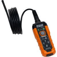
The Klein Tools VDV500-223 Digital Probe-Pro is a professional-series digital and analog tone tracer, featuring an inductive probe with speaker for amplification, and LED light for use in dark spaces. It also features a headphone jack for use in extreme noise environments.
- Operating Altitude: 6562 ft. (2000 m) maximum
- Relative Humidity: 10% – 90% non-condensing
- Operating Temp: 32° to 122° F (0° to 50°C)
• Storage Temp: -4^ to 140^ F ( -20^ to 60^ C) - Dimensions: 1.92" × 9.96" × 1.32" (49 × 253 × 34 mm)
• Weight: 6.88 oz. (195 g) including batteries - Battery Type: 4 × 1.5V AAA Alkaline
- Battery Life: Active: 20 hours
Standby/Storage 3 years
• Auto-Power Off: After 15 minutes of inactivity
Specifications subject to change.
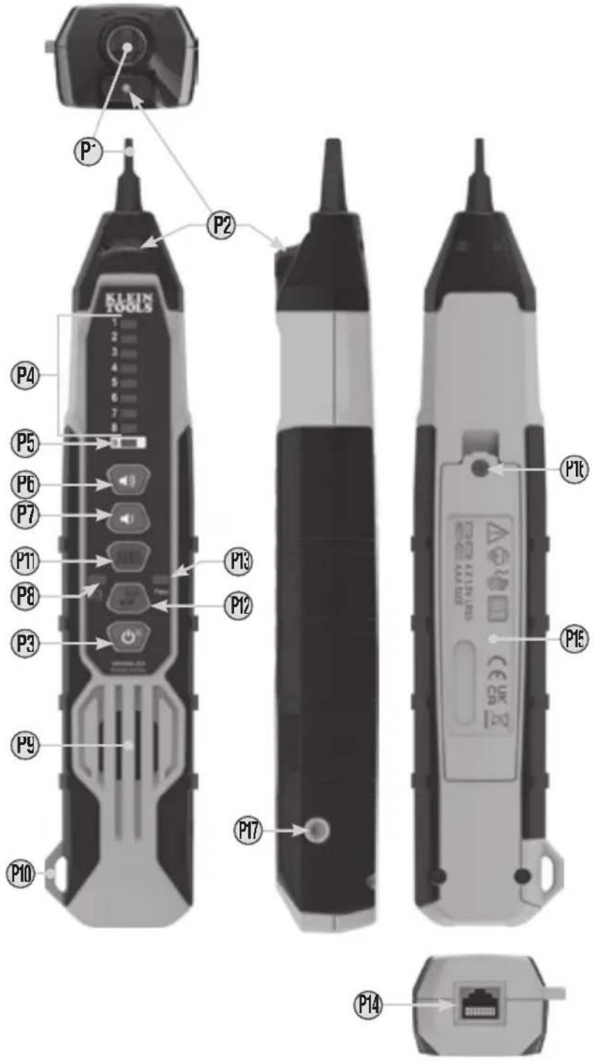
FEATURE DETAILS
P1 Replaceable Inductive Polymer Tip (VDV999-070
P2 Worklight
P3 Power/Worklight On/Off Button
P4 Wire Map Indicators*
P5 Shield Indicator'
*P4 + P5 together constitute Signal Strength Indicator Bars
P6 Volume Increase Button
P7 Volume Decrease Button
P8 Battery Status Indicator
Pg Speaker
P10 Lanyard Slot
P11 Digital Toning Mode Buttor
P12 Analog Toning Mode / 60Hz Filter On/Off Button
P13 Filter Indicator
P14 RJ45 Porl
P15 Battery Cover
P16 Battery Cover Screw (#2 Phillips)
P17 3.5mm Headphone Jack*
*⚠️ CAUTION: Excessive volume can cause permanent hearing damage. Use as low a volume as possible.
FEATURE DETAILS
| SYMBOLS ON PROBE | |||
 | Warning or Cautior |  | Conformité Européenne: Conforms with European Economic Area directives |
 | Always wear approved eye protector |  | UKCA: UK Conformity Assessment |
 | Do NOT use or energized circuits |  | WFFF· Electronics disposa |
| Read instructions | |||
⚠️ WARNINGS
To ensure safe operations and service of the instrument, follow these instructions. Failure to observe these warnings can result in fire, electric shock, severe injury or death.
- The Digital Probe-Pro is designed for use on extra-low voltage cabling systems (less than 60V) for testing when NOT energized.
- DO NOT use instrument if wet, as it could pose a shock hazard.
• DO NOT use instrument if damaged in any way.
• Turn off instrument before attempting to replace batteries - The battery door must be in place and secure before you operate the instrument.
- DO NOT open the case, other than the battery compartment.
OPERATING INSTRUCTIONS
READ ALL INSTRUCTIONS BEFORE OPERATING AND RETAIN INSTRUCTIONS FOR FUTURE REFERENCE
TURNING DIGITAL PROBE-PRO AND WORKLIGHT ON/OFF
- Turn the probe on by pressing the Power On/Off Button P3 once
- When the probe is on, press the Power On/Off Button P3 to turn the worklight on/off.
- To turn off the probe, press and hold the Power On/Off Button P: for more than 2 seconds.
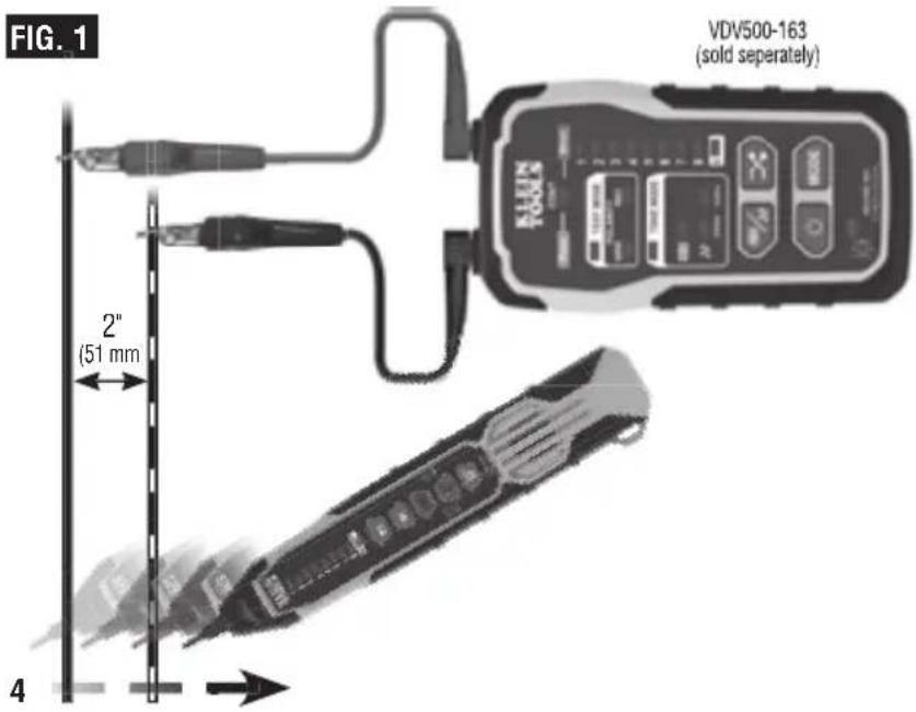
TRACING PAIRED WIRES (FIG. 1)
- Connect tone generator (VDV500-163 Digital Toner-Pro recommended, sold separately) to the wires of the pair to be traced, per tone generator's instructions.
- Turn the Digital Probe-Pro on by pressing the Power On/Off button (P3).
- At the far end of the cable, spread the wires apart at least 2" (51 mm), if possible.
-
If performing analog toning, first ensure the Digital Toner-Pro is set to analog toning mode (refer to VDV500-163 instruction manual.) Then ensure the Digital Probe-Pro is set to analog mode by pressing the Analog Mode button (P1). The Analog Mode Button will illuminate green when in analog mode. If performing digital toning, first ensure the Digital Toner-Pro is set to digital toning mode (refer to VDV500-163 instruction manual.) Then ensure the Digital Probe-Pro is set to digital mode by pressing the Digital Mode Button (P1). The Digital Mode Button will illuminate blue when in digital mode.
-
Use the Digital Probe-Pro to scan the cable's wire pairs. Move the Digital Probe-Pro's tip (P1) slowly across the wires (FIG. 1). The Digital Probe-Pro's volume and Signal Strength Indicator bars (P4 + P5) will increase as it approaches the toned pair. When the Digital Probe-Pro's volume and Signal Strength Indicator bars are high over the first wire, low in the middle (between) the two wires, and high over the second wire, you have located the pair of wires you are tracing. Use the Volume Increase (P6) and Volume Decrease (P7) buttons to adjust the volume.
text_image
FIG. 1 VDV500-163 (sold separately) 2" (51 mm) 4OPERATING INSTRUCTIONS
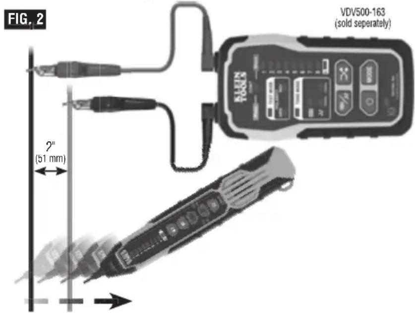
TRACING NON-PAIRED WIRES (FIG. 2)
- Connect tone generator (VDV500-163 Digital Toner-Pro recommended, solc separately) to the wires to be traced, following the tone generator's instructions.
- Turn the Digital Probe-Pro on by pressing the Power On/Off button P3.
- At the far end of the cable, spread the wires at least 2" (51 mm) apart, if possible.
- If performing analog toning, first ensure the Digital Toner-Pro is set to analog toning mode (refer to VDV500-163 instruction manual), then ensure the Digital Probe-Pro is set to analog mode by pressing the Analog Mode Button (P12). The Analog Mode Button will illuminate green when in analog mode.
- If performing digital toning, first ensure the Digital Ioner-Pro is set to digital toning mode (refer to VDV500-163 instruction manual.) Then ensure the Digital Probe-Pro is set to digital mode by pressing the Digital Mode Button P1. The Digital Mode Button will illuminate blue when in digital mode.
- Use the Digital Probe-Pro to scan the cable's wire pairs. Move the Digital Probe-Pro's tip P1 slowly across the wires. The Digital Probe-Pro's volume and Signal Strength Indicator bars P4 + P5 will increase as it approaches the toned wire.
text_image
FIG. 2 VDV500-163 (sold separately) 2" (51 mm)RJ45 TERMINATED DATA CABLE WIRE MAP TESTING
- Insert one end of the data cable to be tested into the RJ45 port on the Digital Toner-Pro (VDV500-163).
- Insert the opposite end of the cable into the Digital Probe-Pro's RJ45 Port P14.
- Set the Digital Toner-Pro into Mapping mode (refer to VDV500-163 instruction manual). The Digital Probe-Pro will automatically go into mapping mode when the toner is set to mapping mode.
- A wire pin-to-pin map will be displayed on both the Toner and Probe. The Toner's Wire Map Indicators will slowly blink in order 1 thru 8, to indicate which pin on the Toner end of the cable is being mapped. Simultaneously, the Probe's Wire Map Indicators (P4) will illuminate to indicate which pin on the Probe end of the cable is connected to the actively indicated pinout on the Toner end; this enables detection of mis-wired cables or cable faults. (for example, if pin 3 on the Toner end of the cable is connected to pin 6 on the Probe end of the cable, when the Toner's #3 Wire Map Indicator illuminates, the Probe's #6 Wire Map Indicator will illuminate).
- If the cable being mapped is terminated in T568A, T568B, or Straight-Through wiring, the Probe's Wire Map Indicators (P4) will illuminate 1 through 8, in the order of contact pin termination, in unison with the Toner's Wire Map Indicators. A short circuit between wires is indicated by simultaneously illuminating all effected wires' LEDs on both the toner and probe during the detection sequence. For an open circuit, the wire's LED on both the toner and probe is not illuminated during the detection sequence.
- If the cable being tested in shielded, the Shield Indicator on both the Toner and Probe P5 will illuminate at the end of each sequence.
- The test will be repeated until one or both ends of the cable is/are disconnected, or until the Toner's mode is cycled out of Mapping mode
NOTE: The Digital Probe-Pro cannot ID digital/analog tone signals while in mapping mode.
OPERATING INSTRUCTIONS
USING THE 60HZ FILTER
The Digital Probe-Pro has a 60Hz filter to help trace cables/wires when toning near devices running on 60Hz. Press the Analog Toning Mode / 60Hz Filter On/Off Button P12 to turn the 60Hz filter on/off. The Filter Indicator P13 will illuminate when the 60Hz filter is on
NOTE: 60Hz filtering can only be used with analog toning.
MAINTENANCE
BATTERY REPLACEMENT
When the Battery Status Indicator Ⓞ blinks, the batteries must be replaced.
- Turn off instrument(s) before attempting to replace batteries
- Loosen screw P16 on battery cover P15.
- Remove and properly dispose of four 1.5V AAA batteries
- Install new batteries (note proper polarity).
- Replace battery cover and fasten securely with screw.

To avoid risk of electric shock, do not operate while battery door is removed.
TIP REPLACEMENT (KLEIN CAT. NO. VDV999-070)
The tip Ⓟ of the Digital Probe-Pro is replaceable if damaged:
- Turn tip 1/4 turn and pull gently to remove.
- Insert new tip with key in proper orientation and push gently
- Rotate 1/4 turn to lock into place
CLEANING
Be sure instrument is turned off and wipe with a clean, dry lint-free cloth. Do not use abrasive cleaners or solvents.
STORAGE
Remove the batteries when instrument is not in use for a prolonged period of time. Do not expose to high temperatures or humidity. After a period of storage in extreme conditions exceeding the limits mentioned in the GENERAL SPECIFICATIONS section, allow the equipment to return to normal operating conditions before using
FCC & IC COMPLIANCE
See this product's page at www.kleintools.com for FCC compliance information.
Canada ICES-003 (B) / NMB-003 (B)
WARRANTY
Do not place equipment and its accessories in the trash. Items must be properly disposed of in accordance with local regulations. Please see www.epa.gov/recycle for additional information.
CUSTOMER SERVICE
KLEIN TOOLS, INC.
450 Bond Street Lincolnshire, IL 60069 1-800-553-4676
customerservice@kleintools.com www.kleintools.com