
LDE 16-8 125 R - Grinder Flex - Free user manual and instructions
Find the device manual for free LDE 16-8 125 R Flex in PDF.

| Product type | Concrete grinder |
| Brand | Flex |
| Model | LDE 16-8 125 R |
| Mains voltage | 230 V / 50 Hz |
| Protection class | II |
| Power consumption | 1 600 W |
| Power output | 900 W |
| No-load speed | 7 800 rpm |
| Rated speed | 9 000 rpm |
| Max. disc diameter | 125 mm |
| Spindle thread | M14 |
| Weight | 3.0 kg |
| Speed preselection | 6 positions (1 to 6) |
| Adjustable handle | Yes, every 15° |
| Sound pressure level | 87 dB(A) |
| Sound power level | 98 dB(A) |
| Vibration value | 3.2 m/s² |
| Main functions | Sanding and smoothing of concrete, plaster, screeds, sandstone, asphalt |
| Dust extraction | Connection for class M vacuum cleaner (32 mm nozzle) |
| Safety | Spindle lock, adjustable protective guard, hold-on switch |
| Included accessories | Maintenance wrench, hex key |
| Cleaning | Dry compressed air; do not use water |
| Repairability | Repairs by FLEX authorized service center |
Frequently Asked Questions - LDE 16-8 125 R Flex
User questions about LDE 16-8 125 R Flex
0 question about this device. Answer the ones you know or ask your own.
Ask a new question about this device
Download the instructions for your Grinder in PDF format for free! Find your manual LDE 16-8 125 R - Flex and take your electronic device back in hand. On this page are published all the documents necessary for the use of your device. LDE 16-8 125 R by Flex.
USER MANUAL LDE 16-8 125 R Flex
natural_image
Illustration of a power tool with meshing and close-up insets showing the end eye (no text or symbols)de Originalbetriebsanleitung 3
en Original operating instructions 14
fr Notice d'instructions d'origine 25
it Istruzioni per l'uso originali 36
es Instrucciones de funcionamiento originales ..... 47
pt Instruções de serviço originais ..... 58
nl Originele gebruiksaanwijzing 69
da Originale driftsvejledning 80
no Originale driftsanvisningen 91
sv Originalbruksanvisning 102
fi Alkuperäinen käyttöohjekirja 113
el Auθεντικές οδηγίες χειρισμού ..... 124
tr Orijinal işletme kılavuzu 136
pI Instrukcja oryginalna 147
hu Eredeti üzemeltetési útmutató 159
cs Originální návod k obsluze ..... 170
sk Originálny návod na obsluhu 181
hr Originalna uputa za rad 192
sl Izvirno navodilo za obratovanje 203
ro Instructiuni de functionare originale 214
bg Оригинално упътване за експлоатация ..... 225
ru Оригинальная инструкция по эксплуатации ..... 236
et Originaalkasutusjuhend 249
It Originali naudojimo instrukcija 260
Iv Lietošanas pamācības oriģināls 271
ar إرشادات التشفيل الأصلية 291
Inhalt
Verwendete Symbole 3
Symbole am Gerät 3
natural_image
Close-up of a mechanical component with a highlighted section and directional arrow (no text or symbols)natural_image
Mechanical component with directional arrows indicating motion or flow (no text or symbols)natural_image
Person using a power tool on a workbench (no text or symbols visible)natural_image
Person using a power tool to cut or spread material on a workbench (no text or symbols visible)natural_image
Mechanical assembly diagram showing a bolt and nut assembly with directional arrows indicating motion (no text or symbols)Bürstenkranz

Peter Lameli
Technical Head

Klaus Peter Weinper Head of Quality Department (QD)
15.12.2020
Symbols used in this manual ..... 14
Symbols on the device ..... 14
Important safety information ..... 14
Noise and vibration 17
Technical data 18
Overview 19
Instructions for use 20
Maintenance and care 23
Disposal information 24
C ∈ conformity 24
Exemption from liability 24
Symbols used in this manual

WARNING!
Denotes impending danger. Non-observance of this warning may result in death or extremely severe injuries.

CAUTION!
Denotes a potentially dangerous situation. Non-observance of this warning may result in injury or damage to property.

NOTE
Denotes hints on use and important information.
Symbols on the device

Before switching on the power tool, read the operating manual.

Wear protective goggles.

Disposal information for the old tool (see page 24).
Important safety information

WARNING!
Before using the power tool, please read the following and act accordingly:
– These operating instructions
- The "General safety instructions" on the handling of power tools in the enclosed booklet (leaflet no.: 315.915)
- The currently valid site rules and the regulations for the prevention of accidents
This power tool is state of the art and has been assembled in accordance with the acknowledged safety regulations.
Nevertheless, when in use, the power tool may pose a danger to life and limb of the user or a third party, or the power tool or other items could be damaged. The power tool may be operated only
– for its intended use,
– in perfect working order.
Faults which compromise safety must be repaired immediately.
Intended use
The renovation sander LD 16-8 125 R / LDE 16-8 125 R is designed
– for commercial use in industry and trade
– for dry sanding and smooth finishing concrete, plaster, screed, sandstone, fireclay and tarmac
– for sanding off paint and adhesive residue on concrete or screed
– for use with diamond tools that are offered by FLEX for these power tools and are authorised to run at a speed of at least 9000 rpm.
It is not permitted to use cutting discs, rubbing discs, flap discs or wire brushes.
When using the renovation sander LD 16-8 125 R / LDE 16-8 125 R, connect a class M dust extractor.
Safety instructions

WARNING!
Read all safety notices and instructions.
Failure to comply with the safety notices and instructions may result in electric shock, fire and/or serious injuries Keep all safety notices and instructions in a safe place for future reference.
■ This power tool is to be used as a sander/grinder. Observe all of the safety notices, instructions, diagrams and specifications included with the tool.
Failure to heed the following instructions may result in electric shock, fire and/or serious injury.
■ This power tool is not suitable for sanding with sandpaper, working with wire brushes, polishing and cutting discs.
Hazards and injuries can ensue if the power tool is not used in the way intended.
■ Do not use accessories other than those specifically provided and recommended by the manufacturer for this power tool.
Just because an accessory can be attached to the power tool does not mean that it is safe to use.
■ The approved speed of the tool/attachment must be at least as high as the maximum speed specified on the power tool.
Accessories that rotate faster than permitted could disintegrate and broken parts could fling off at speed.
■ The outside diameter and the thickness of the tool/attachment must be within the capacity rating of the power tool.
Tools/attachments of the wrong size cannot be shielded or controlled sufficiently.
Sanding/grinding discs, sanding/grinding wheels or other accessories must fit precisely on the spindle of your power tool.
Tools/attachments that do not fit properly on the spindle of the power tool will rotate unevenly, vibrate heavily and cause loss of control.
■ Do not use damaged tools/attachments. Before each use, check tools/attachments for chips and cracks, check
grinding/sanding plates for fractures and look for signs of major wear and tear. If the power tool or tool/attachment falls on the ground, check whether it is damaged or use an undamaged power tool and/or tool/attachment. Once the tool/attachment has been inspected and installed, keep yourself and others away from the rotating tool/attachment and allow the power tool to operate at full speed for one minute.
If tools/attachments are damaged they will usually break in this test period.
■ Wear personal protective equipment. Wear a visor, eye protection or goggles depending on use. If appropriate, wear a dust mask, ear defenders, safety gloves or special apron to protect against small grinding particles and material fragments.
Eyes should be protected against foreign bodies that are flung into the air during various applications. Dust masks or respirators must be capable of filtering out dust generated during use. Hearing damage could ensue if you are exposed to loud noise for extended periods.
■ Make sure that others are kept a safe distance from your working area. All persons who enter the working area are required to wear personal protective equipment.
Fragments of the workpiece or broken tools/attachments could be flung into the air and cause injuries even outside the immediate working area.
■ Hold the power tool by the insulated gripping surfaces when performing an operation where the cutting accessory could contact hidden wiring or its own power cord.
Contact with a live wire may make exposed metal parts of the power tool live and cause an electric shock.
- Keep the power cord away from rotating tools/attachments.
If you lose control over the power tool, the power cord could be cut or pulled and draw your hand or arm into the rotating tool/attachment.
■ Never place the power tool down before the tool/attachment has come to rest completely.
If the tool/attachment is still rotating, it could come into contact with the surface and cause loss of control over the power tool.
■ Never leave the power tool running while carrying it.
Your clothing could be caught through accidental contact with the rotating tool/attachment and the tool/attachment could cut into your skin.
■ Clean the ventilation slots of the power tool regularly.
The motor fan draws dust into the housing and a heavy build-up of metal dust could pose an electrical hazard.
■ Do not use the power tool in the vicinity of combustible materials.
Sparks could set these materials alight.
■ Do not use tools/attachments that require liquid coolant.
The use of water or other liquid coolants could cause electric shock.
Special safety notices for sanding/grinding
■ Abrasives may only be used for the recommended applications.
For example: Never sand with the side of a diamond sanding plate.
Diamond sanding plates are designed to abrade material with the underside of the sanding plate. Force imparted on the side could cause disintegration of the abrasive plate.
■ Only ever use undamaged clamping flanges of the correct size and shape for the selected tool/attachment.
Suitable flanges support the tool/attachment and in doing so reduce the risk of breakage.
■ Do not use worn tools/attachments from larger power tools.
Tools/attachments from larger power tools are not designed for the higher speeds of smaller power tools and could break.
Kickback and related safety notices
Kickback is the sudden reaction to a trapped or seized rotating tool/attachment, such as a sanding disc, sanding plate, wire brush and such like. If these items seize up or become trapped, the rotating attachment will stop abruptly. This results in an uncontrolled power tool accelerating against the direction of rotation of the tool/attachment in the seized area.
If e.g. a sanding disc becomes trapped or seized in the workpiece, the edge of the sanding disc will get caught from cutting into the workpiece and cause the sanding disc to disintegrate or the power tool to kick back.
The sanding disc would then move towards or away from the user depending on the direction of rotation of the disc in the seized area. This can cause sanding discs to break as well.
A kickback occurs from incorrect or faulty use of the power tool. It can be mitigated through suitable precautions, which are described as follows.
- Maintain a firm grip with both hands on the power tool and position your arms in such a way that kickback forces can be resisted. Always use the auxiliary handle, if present, for the highest level of control over kickback forces or starting torque.
The person operating the tool can master forces from kickback and starting torque provided suitable measures are taken.
■ Always keep hands away from rotating tools/attachments.
The tool/attachment could move over your hand during a kickback.
- Keep your body away from the area in which the power tool will move in the event of a kickback.
Kickback propels the power tool in the direction opposite the movement of the grinding/sanding disc in the seized area.
■ Exercise greater caution when working in corners, at sharp edges and such like. Prevent tools/attachments recoiling from the workpiece and becoming jammed.
The tool/attachment has a tendency to jam in corners, at sharp edges or when it recoils. As a result, control could be lost or kickback caused.
■ Do not use chainsaw discs or serrated cutting discs.
Tools/attachments of this kind frequently lead to kickback or loss of control over the power tool.
Additional safety notices
■ Use only extension cables approved for outside use.
■ Sanding lead-based paints is not recommended. The removal of lead-based paints should be carried out by a specialist.
■ Do not work on materials that release hazardous substances (e.g. asbestos). Implement safety measures if there is a danger of dust being generated that is hazardous to health, combustible or explosive. Wear a dust mask. Use local exhaust ventilation.

MATERIAL DAMAGE!
■ The mains voltage and the voltage specifications on the rating plate must correspond.
Noise and vibration

WARNING!
The specified measured values refer to new power tools. Daily use causes the noise and vibration values to change.

NOTE
The vibration emission level given in this information sheet has been measured in accordance with a standardised test given in EN 60745 and may be used to compare one tool with another. It may be used for a preliminary assessment of exposure. The declared vibration emission level represents the main applications of the tool. However, if the tool is used for different applications, with different cutting accessories or poor maintenance, the vibration emission level may differ. This may significantly increase the exposure level over the total working period.
To make an accurate estimation of the vibration exposure level, it is also necessary to take into account the times when the tool is switched off or running but not actually in
use. This may significantly decrease the exposure level over the total working period. Identify additional safety measures to protect the operator from the effects of vibration such as: tool and accessory maintenance, keep hands warm, standard operating procedures.

CAUTION!
Wear ear defenders at a sound pressure above 85 dB(A).
Technical data
| LD 16-8 125 R LDE 1 | 6-8 125 R | ||
| Machine type Renovation sander | |||
| Mains voltage V/Hz 230/50 | |||
| Protection class | II / ☐ | ||
| Power input W 1,600 | |||
| Power output W 900 | |||
| Speed rpm 7,800 | 1 - 4,5002 - 5,2003 - 5,9004 - 6,4005 - 7,1006 - 7,800 | ||
| Rated speed rpm 9000 | |||
| Tool holder M14 | |||
| Max. disc diameter mm | 125 | ||
| Weight according to “EPTA procedure 1/2003” | kg | 3.0 | |
| A-rated noise level in accordance with EN 60745 (see "Noise and vibration") | |||
| Sound pressure level L_PA | dB(A) | 87 | |
| Sound power level L_WA | dB(A) | 98 | |
| Uncertainty K | dB | 3 | |
| Vibration total value in accordance with EN 60745 (see "Noise and vibration") | |||
| Emissions value a_h when using diamond-coated grinding disc | m/s ^2 | 3.2 | |
Overview
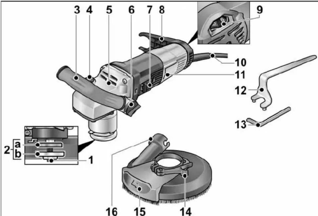
1 Spindle with threaded flange
2 a Clamping flange
b Clamping nut
3 Handle, adjustable
4 Spindle lock
For holding the spindle during tool change.
5 Gear head
With air outlet and direction of rotation arrow.
6 Handle adjustment knob
7 Rocker switch
For switching on and off.
With detent position for non-stop operation.
8 Hose retainer
9 Setting wheel for speed preselection
10 4.0 m power cord with plug
11 Rating plate
12 Stop wrench
13 Allen key
14 Clamping lever
15 Swivelling edge segment
16 Connection for extractor
Instructions for use
Before initial operation
Unpack the power tool and accessories and check that no parts are missing or were damaged during transport.
Attaching and changing the abrading tool

WARNING!
Before performing any work on the power tool, pull out the mains plug.
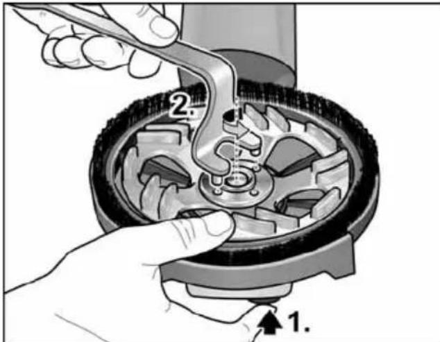
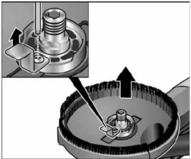
■ Press and hold the spindle lock (1.).
■ Using the stop wrench, loosen the clamping nut on the spindle in anti-clockwise direction and remove (2.).

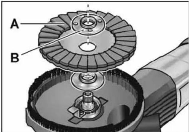
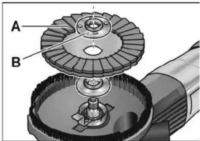
■ Insert the diamond grinding wheel (A) in the correct position.
■ Screw the clamping nut (B) onto the spindle with the shoulder facing upwards.
■ Press and hold the spindle lock.
■ Tighten the clamping nut with the stop wrench.
■ Check the position of the protective hood.
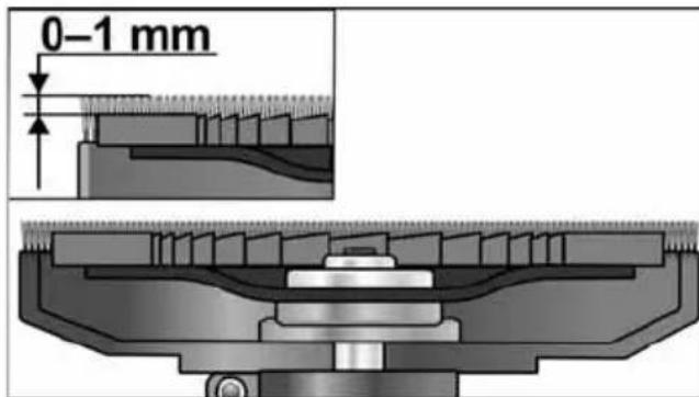
The brush ring should protrude approx. 0–1 mm over the sanding plate. Adjust if necessary (see "Adjusting the protective hood").
■ Insert the mains plug into the socket.
■ Switch on the power tool (without detent) and allow it to run for approx.
30 seconds. Check for imbalance and vibrations.
■ Switch off the power tool.
Adjusting the handle

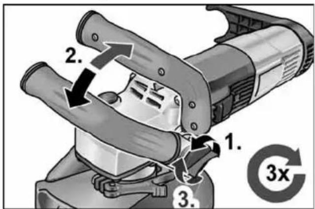
■ Loosen the handle adjustment knob approx. 3 turns in anti-clockwise direction.
■ Move the handle to the desired position (15° detent).
Ensure that it engages correctly.
■ Tighten the handle adjustment knob in clockwise direction.
NOTE
The handle can be moved to the other side of the power tool if needed.
Adjusting the protective hood
i NOTE
The brush ring should protrude approx. 0–1 mm over the sanding plate. The protective hood can be adjusted in height to compensate for wear of the diamond sanding plate.
■ Release the clamping lever on the protective hood.
■ Adjust the protective hood to the desired height.
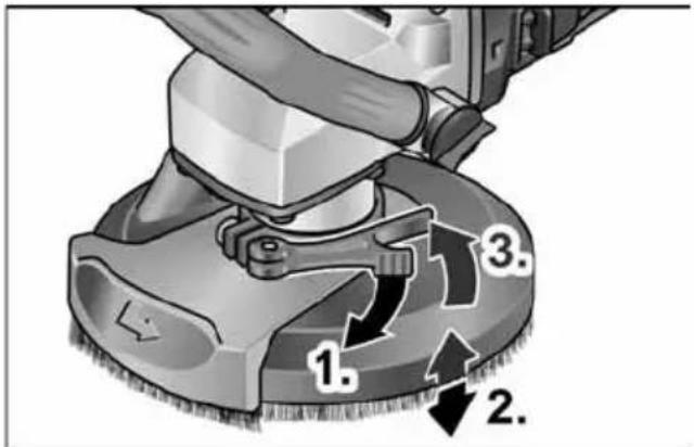
■ Tighten the clamping lever.
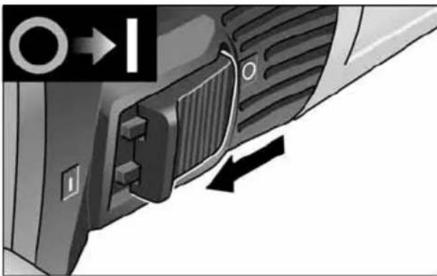
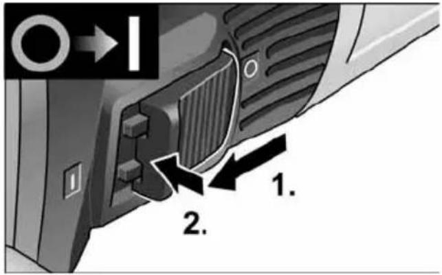
Switching the power tool on/off Short-term operation without detent
natural_image
Close-up of a car's front panel showing a button and ventilation slots (no text or symbols visible)■ Push the rocker switch forwards and hold.
■ Release the rocker switch to switch off.
Non-stop operation with detent
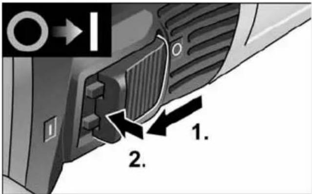
■ Push the rocker switch forwards and engage by pressing the front part.
i NOTE
If there is a power failure, the switched on power tool will not start running again.
Switching off the equipment:
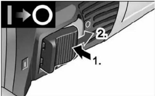
■ To switch off, release the rocker switch by pressing the rear part.
i NOTE
The tool will switch off automatically in the event of a short overload. To restart the tool, switch off and back on again. If overheating occurs due to overload during non-stop operation, the speed of the power tool will be reduced automatically until the power tool has cooled down sufficiently. At the end of the cooling mode, the tool switches off automatically.
To restart the tool, switch off and back on again.
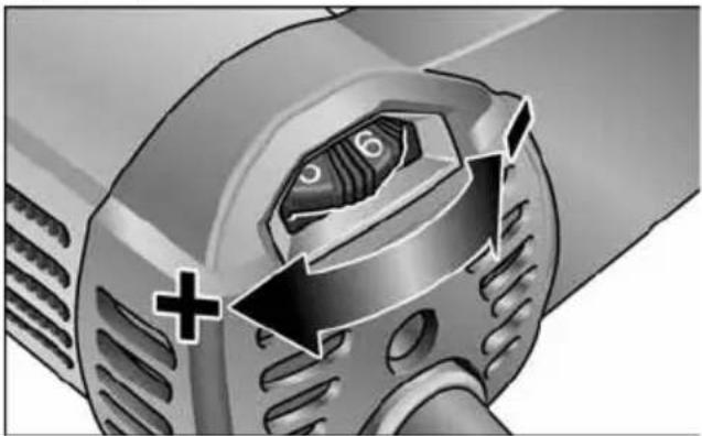
Speed preselection
natural_image
Close-up of a mechanical component with directional arrows and a plus sign, no readable text or symbols present.■ To set the operating speed, move the dial to the required value.

CAUTION!
Risk of injury from disintegration of the tool. Use a tool appropriate for the task at hand.

NOTE
Avoid exerting excess pressure on the tool when sanding/grinding at low speed (1-3) as it will otherwise quickly overheat.
Using a dust extraction system

NOTE
The use of a class M FLEX dust extractor is recommended.
■ Connect suction hose to the 32 mm connector.
■ Engage the suction hose in the hose retainer.
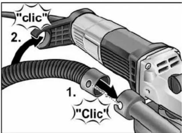
■ Connect the suction hose to the dust extraction system. Observe the operating instructions of the dust extraction system. Check the attachment. Use a suitable adapter if necessary.

NOTE
If your dust extraction system needs a special connection (i.e. a connection other than the 32 mm/36 mm standard connection included in the items supplied with the power tool), contact the dust extractor vendor to obtain a suitable adapter.
Working with the power tool

WARNING!
The rotating sanding plate must not come into contact with sharp, protruding items. Risk of kickback! Sanding plate damage. If the sanding plate is damaged or heavily worn, it must be replaced without fail.

CAUTION!
Always hold the power tool firmly with both hands.
- Secure abrasive.
- Connect dust extraction system.
- Insert the mains plug.
- Switch on dust extraction.
-
Switch on the power tool.
-
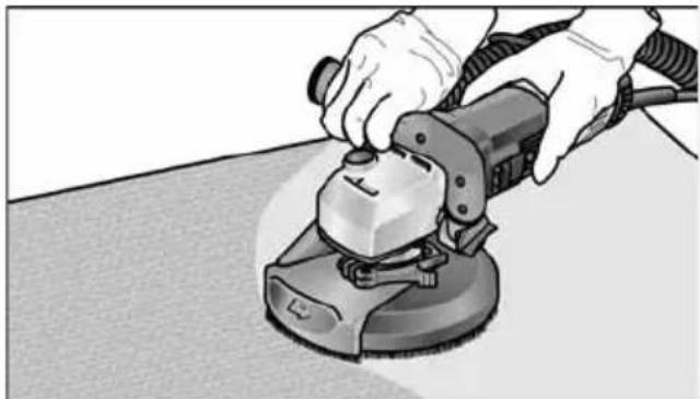
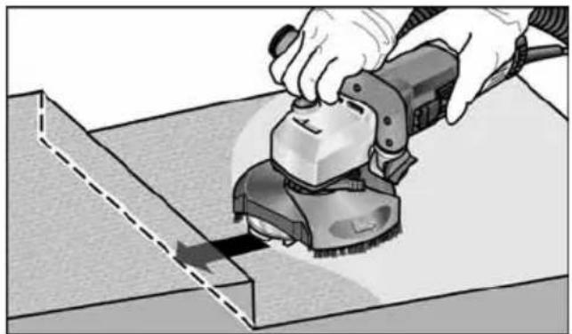
Bring the renovation sander into position on the work surface. The brush ring / rubber suction ring must be flush with the work surface.
natural_image
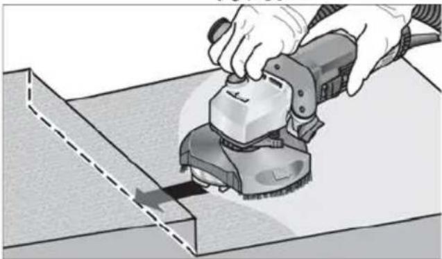
Person using a power tool on a textured surface (no text or symbols visible)- Increase pressure to bring the sanding plate into contact with the work surface. Sweep the renovation sander with overlapping movements when doing this.
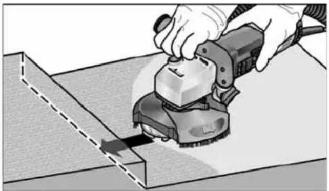
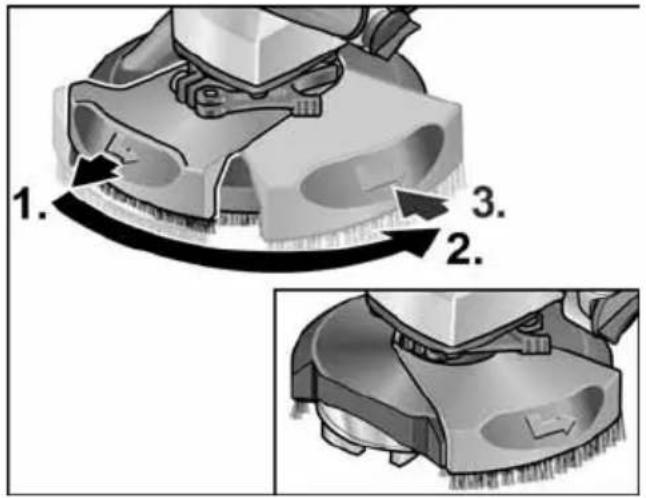
- For sanding in corners :
- Switch off the power tool and wait until the abrasive has stopped moving.
– Pull out the swivelling edge segment and swivel it to the left.
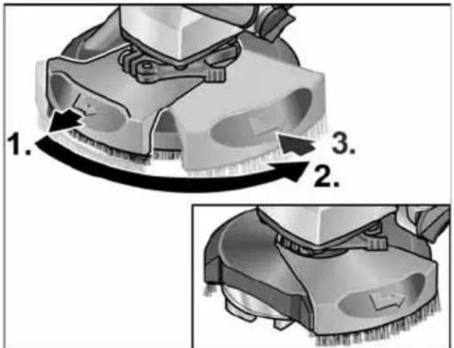
- Switch the power tool back on again.
natural_image
Person using a power tool on a workbench, no visible text or symbols- Switch off the power tool after stopping work and pull out the mains plug.
Replacing the protective hood
The protective hood has a retainer. This must be reinstalled following replacement of the protective hood.
natural_image
Mechanical assembly diagram showing a piston and crankshaft mechanism with directional arrows (no text or labels)Brush ring
The protective hood features a brush ring. This ring fulfils two functions:
- Since the brush ring protrudes over the surface of the sanding plate, it is the first thing to come into contact with the work surface. This brings the sanding plate into position parallel with the work surface before the abrasive makes contact with the work surface. It prevents any ruts being cut into the surface by the edge of the sanding plate.
- The ring holds back dust before it is extracted by the vacuum cleaner. If the brush ring is damaged or exhibits excessive signs of wear, it should be renewed. A replacement brush set is available from any FLEX customer service centre.
Rubber suction ring
If the rubber suction ring is damaged or exhibits signs of excessive wear, it should be renewed.
A replacement suction ring is available from any FLEX customer service centre.
Maintenance and care

WARNING!
Before performing any work on the power tool, pull out the mains plug.
Cleaning

WARNING!
Do not use water or liquid detergents.
■ Regularly blow out housing interior and motor with dry compressed air.
■ Clean protective hood and swivelling edge segment with dry compressed air.
Repairs
Repairs may only be carried out by an authorised customer service centre.

NOTE
Do not loosen the screws on the motor housing during the warranty period. Failure to comply with this requirement will invalidate any claims under the manufacturer's warranty.
Spare parts and accessories
Other accessories, in particular cutting accessories, can be found in the manufacturer's catalogues.
Exploded drawings and spare-part lists can be found on our homepage:
www.flex-tools.com
Disposal information

WARNING!
Render disused power tools unusable by removing the power cord.

EU countries only
Do not dispose of electric power tools in the household waste!
In accordance with the European
directive 2012/19/EU on Waste Electrical and Electronic Equipment and its incorporation into national law, end-of-life electric power tools must be collected separately and recycled in an environmentally-friendly manner.

NOTE
Please ask your dealer about disposal options.
CE conformity
We declare on our sole responsibility that the product described under “Technical data” conforms to the following standards or normative documents:
EN 60745 according to the provisions of directives 2014/30/EU, 2006/42/EC, 2011/65/EU.
Responsible for technical documents:
Peter Lameli Technical Head
Klaus Peter Weinper
Head of Quality Department (QD)
15.12.2020
Exemption from liability
The manufacturer and its agent are not liable for any damage and lost profit due to interruption in business caused by the product or by an unusable product.
The manufacturer and its agent are not liable for any damage which was caused by improper use of the power tool or by use of the power tool with products from other manufacturers.
Table des matières
natural_image
Close-up of a mechanical component with a button and arrow indicator (no readable text or symbols)natural_image
Close-up of a mechanical component with directional arrows and a plus sign, no readable text or symbols present.natural_image
Person using a power tool on a workbench (no text or symbols visible)natural_image
Illustration of a hand using a power tool to cut or spread material on a workbench (no text or symbols visible)natural_image
Mechanical assembly diagram showing a bolt and nut assembly with an inset view of the component (no text or labels)Brosses en couronne
Peter Lameli Technical Head

Klaus Peter Weinper Head of Quality Department (QD)
15.12.2020
natural_image
Close-up of a car's side panel showing a grille and vent, with a directional arrow indicating left motion (no text or symbols)natural_image
Close-up of a mechanical component with directional arrows and a plus sign, no readable text or symbols present.natural_image
Person using a power tool on a workbench (no text or symbols visible)natural_image
Person using a power tool to cut or spread material on a workbench (no text or symbols visible)natural_image
Mechanical assembly diagram showing a bolt and nut assembly with directional arrows (no text or labels)Spazzola a corona
Peter Lameli Technical Head
Klaus Peter Weinper Head of Quality Department (QD)
15.12.2020
■ Ajustar la palanca de ajuste.
natural_image
Close-up of a car's side panel showing a handle and vent, with no visible text or symbolsnatural_image
Close-up of a mechanical component with directional arrows and a plus sign, no readable text or symbols present.natural_image
Person using a power tool on a workbench (no text or symbols visible)natural_image
Illustration of a hand using a power tool to cut or spread material on a flat surface (no text or symbols visible)natural_image
Mechanical assembly diagram showing a bolt inserted into a gear-like component, with an inset close-up highlighting the mechanical feature (no text or symbols present)Anillo cepillo

Peter Lameli
Technical Head

Klaus Peter Weinper Head of Quality Department (QD)
15.12.2020
natural_image
Cross-sectional diagram of a mechanical assembly (no visible text or labels)A coroa de lixar deve estar saliente ca. de 0–1 mm do prato de lixar.
natural_image
Close-up of a car's side panel showing a grille and vent, with no visible text or symbolsnatural_image
Close-up of a mechanical component with directional arrows and a plus sign, no readable text or symbols present.natural_image
Person using a power tool on a workbench (no text or symbols visible)natural_image
Illustration of a hand using a power tool to cut or spread material on a workbench (no text or symbols visible)natural_image
Mechanical assembly diagram showing a bolt and nut assembly with directional arrows indicating motion (no text or symbols)Coroa de escovas
EN 60745 de acordo com as determinações das directivas 2014/30/UE, 2006/42/CE, 2011/65/UE.
Peter Lameli
Technical Head
Klaus Peter Weinper
Head of Quality
Department (QD)
15.12.2020
natural_image
Close-up of a car's side panel showing a grille and vent, with no visible text or symbolsnatural_image
Close-up of a mechanical component with a central knob and directional arrows, no visible text or symbolsnatural_image
Person using a power tool on a workbench (no text or symbols visible)natural_image
Person using a power tool on a workbench, no visible text or symbolsnatural_image
Mechanical assembly diagram showing a bolt and nut assembly with directional arrows indicating motion (no text or symbols)Borstelkrans
Peter Lameli Technical Head

Klaus Peter Weinper Head of Quality Department (QD)
15.12.2020
natural_image
Close-up of a car's side panel showing a grille and vent, with directional arrows indicating movement (no text or symbols)■ Skub vippekontakten fremad og hold den fast.
■ Slip vippekontakten for at slukke.
natural_image
Close-up of a mechanical component with directional arrows and a plus sign, no readable text or symbols present.natural_image
Person using a power tool on a workbench (no text or symbols visible)natural_image
Illustration of a hand using a power tool to cut or spread material on a workbench (no text or symbols visible)natural_image
Mechanical assembly diagram showing a bolt and nut assembly with directional arrows (no text or labels)Børstekrans
Peter Lameli Technical Head
Klaus Peter Weinper Head of Quality Department (QD)
15.12.2020
■ Trekk spennspaken fast.
natural_image
Close-up of a car's front panel showing grille and side buttons, with no visible text or symbolsnatural_image
Close-up of a mechanical component with arrows indicating direction and polarity (no text or symbols)natural_image
Person using a power tool on a workbench (no text or symbols visible)natural_image
Person using a power tool on a workbench, no visible text or symbolsnatural_image
Mechanical assembly diagram showing a bolt and nut assembly with an inset view of the component (no text or symbols)Børstekrans
Vernehetten er utstyrt med en børstekrans. Denne kransen har to funksjoner:
Peter Lameli Technical Head

Klaus Peter Weinper Head of Quality Department (QD)
15.12.2020
natural_image
Close-up of a car's front panel showing a grille and side button, with no visible text or symbols.natural_image
Close-up of a mechanical component with directional arrows and a plus sign, no readable text or symbols present.natural_image
Person using a power tool on a workbench (no text or symbols visible)natural_image
Illustration of a hand using a power tool to cut or spread material on a flat surface (no text or symbols visible)natural_image
Mechanical assembly diagram showing a bolt and nut assembly with directional arrows indicating motion (no text or symbols)Borstkrans
Peter Lameli Technical Head
Klaus Peter Weinper Head of Quality Department (QD)
natural_image
Close-up of a car's front panel showing a button and ventilation slots, with no visible text or symbols.natural_image
Close-up of a mechanical component with arrows indicating direction and polarity (no text or symbols)natural_image
Person using a power tool on a textured surface (no text or symbols visible)natural_image
Illustration of a hand using a power tool to cut a rectangular block, no text or symbols presentnatural_image
Mechanical assembly diagram showing a bolt and nut assembly with an inset view of the component (no text or symbols)Harjareuna
Peter Lameli Technical Head
Klaus Peter Weinper Head of Quality Department (QD)
15.12.2020
natural_image
Cross-sectional diagram of a mechanical assembly (no visible text or labels)natural_image
Close-up of a mechanical component with a highlighted section and directional arrow (no text or symbols)natural_image
Close-up of a mechanical component with directional arrows and a plus sign, no readable text or symbols present.natural_image
Person using a power tool on a workbench (no text or symbols visible)natural_image
Person using a power tool to cut or spread material on a workbench (no text or symbols visible)natural_image
Mechanical assembly diagram showing a piston and nut assembly with an inset view of the piston (no text or labels)Στεφάνη βούρτσας

Peter Lameli
Technical Head

Klaus Peter Weinper
Head of Quality
Department (QD)
natural_image
Close-up of a car's side panel showing a grille and handle, with no visible text or symbolsnatural_image
Close-up of a mechanical component with directional arrows indicating motion or movement (no text or symbols)natural_image
Person using a power tool on a workbench (no text or symbols visible)natural_image
Illustration of a hand using a power tool to cut or spread material on a workbench (no text or symbols visible)natural_image
Mechanical assembly diagram showing a bolt and nut assembly with directional arrows (no text or labels)Fırça kasnağı
Peter Lameli Technical Head

Klaus Peter Weinper Head of Quality Department (QD)
15.12.2020
natural_image
Close-up of a car's side panel showing a grille and vent, with a directional arrow indicating left motion (no text or symbols present)natural_image
Close-up of a mechanical component with directional arrows indicating motion or movement (no text or symbols)natural_image
Person using a power tool on a textured surface (no text or symbols visible)natural_image
Illustration of a hand using a power tool to cut or spread material on a workbench (no text or symbols visible)natural_image
Mechanical assembly diagram showing a bolt and nut assembly with directional arrows indicating motion (no text or symbols)Wieniec szczotkowy
Peter Lameli Technical Head
Klaus Peter Weinper
Head of Quality
Department (QD)
1 Orsó menetes peremmel
2 a Szorítókarima
b Szorítóanya
natural_image
Close-up of a car's side panel showing a button and ventilation slots, with no visible text or symbols.natural_image
Close-up of a mechanical component with arrows indicating motion or flow, no visible text or symbolsnatural_image
Person using a power tool on a textured surface (no text or symbols visible)natural_image
Illustration of a hand using a power tool to cut or spread material on a workbench (no text or symbols visible)natural_image
Mechanical assembly diagram showing a bolt and nut assembly with directional arrows indicating motion (no text or symbols)Peter Lameli Technical Head
Klaus Peter Weinper Head of Quality Department (QD)
natural_image
Cross-sectional diagram of a mechanical assembly (no text or labels visible)natural_image
Close-up of a car's side panel showing a button and a directional arrow (no text or symbols)natural_image
Close-up of a mechanical component with arrows indicating direction and polarity (no text or symbols)natural_image
Person using a power tool on a workbench (no text or symbols visible)natural_image
Illustration of a hand using a power tool to cut or spread material on a workbench (no text or symbols visible)natural_image
Mechanical assembly diagram showing a bolt and nut assembly with an inset view of the component (no text or symbols)Kartáčový věnec
Peter Lameli Technical Head

Klaus Peter Weinper Head of Quality Department (QD)
15.12.2020
■ Stlačte aretáciu vretena a držte ju stlačenú (1.).
natural_image
Close-up of a car's front panel showing a grille and button, with no visible text or symbolsnatural_image
Close-up of a mechanical component with directional arrows and a plus sign, no readable text or symbols present.natural_image
Person using a power tool on a workbench (no text or symbols visible)natural_image
Person using a power tool on a workbench, no visible text or symbolsnatural_image
Mechanical assembly diagram showing a bolt and nut assembly with an inset view of the component (no text or labels)Kefový veniec

Peter Lameli
Technical Head

Klaus Peter Weinper Head of Quality Department (QD)
15.12.2020
1 Vreteno s prirubnicom s navojem
2 a Stezna prirubnica
b Stezna matica
3 Ručka, podesiva
4 Blokada vretena
Za fiksiranje vretena pri zamjeni alata.
5 Glava prijenosnika
S izlazom zraka i strelicom smjera
vrtnje.
6 Okretni gumb za podešavanje ručke
7 Klizač prekidača
Za uključivanje i isključivanje.
S graničnikom položaja za neprekidan rad.
8 Držač crijeva
9 Kotačić za predodabir broja okretaja
10 Priključni kabel 4,0 m s mrežnim utikačem
11 Označna pločica
12 Zaustavni ključ
13 Imbus ključ
14 Poluga za zatezanje
15 Zakretni rubni segment
16 Priključak za nastavak za usisavanje
Upute za uporabu
Prije stavljanja u pogon
■ Pritisnite blokadu vretena i držite je pritisnutu (1.).
■ Otpustite stežnu maticu s vretena pomoću zaustavnog ključa u smjeru suprotnom od kazaljke na satu i skinite je (2.).
■ Dijamantni brusni tanjur (A) umetnite u ispravnom položaju.
■ Steznu maticu (B) s vijencem okrenutim prema gore uvrnite na vreteno.
■ Pritisnite blokadu vretena i držite je pritisnutu.
■ Steznu maticu zategnite zaustavnim ključem.
■ Provjerite položaj štitnika.

Vijenac s četkama trebao bi stršati preko brusnog tanjura oko 0–1 mm. Po potrebi ispravite (pogledajte „Namještanje štitnika“).
■ Utaknite mrežni utikač u utičnicu.
■ Uključite električni alat (bez uglavljivanja) i ostavite ga da radi otprilike 30 sekundi. Provjerite dolazi li do neuravnoteženosti i vibracija.
■ Isključite električni alat.
Podešavanje ručke
natural_image
Close-up of a car's front panel showing a button and ventilation slots (no text or symbols visible)natural_image
Close-up of a mechanical component with arrows indicating motion or movement, no visible text or symbolsnatural_image
Person using a power tool on a workbench (no text or symbols visible)natural_image
Person using a power tool to cut or spread material on a flat surface (no text or symbols visible)- Po završetku rada isključite električni alat i izvucite mrežni utikač.
Zamjena štitnika
natural_image
Mechanical assembly diagram showing a bolt and nut assembly with directional arrows (no text or labels)Vijenac s četkama
Peter Lameli Technical Head

Klaus Peter Weinper Head of Quality Department (QD)
15.12.2020
■ Pritisnite in držite zaporo vretena (1.).
■ Z zadrževalnim ključem zavrtite vpenjalno matico v levo in jo snemite z vretena (2.).
natural_image
Cross-sectional diagram of a mechanical assembly (no visible text or labels)natural_image
Close-up of a computer mouse with a button and scroll, showing a black arrow pointing to the handle (no text or symbols visible)■ Prekucno stikalo potisnite naprej in ga pridržite.
■ Za izklop prekucno stikalo izpustite.
Neprekinjeno delovanje z uporabo prekucnega stikala
■ Prekucno stikalo potisnite naprej in ga s pritiskom na sprednji del zaskočite.
i OPOMBA
natural_image
Close-up of a mechanical component with arrows indicating direction and polarity (no text or symbols)■ Sesalno cev priključite na sesalnik. Upoštevajte navodila za uporabo sesalnika! Preverite, ali je cev dobro pritrjena! Po potrebi uporabite ustrezen adapter.

OPOMBA
Če boste za svoj sesalnik potrebovali poseben nastavek (tj. nastavek, ki se razlikuje od priloženega 32/36-milimetrskega standardnega nastavka), stopite v stik s svojim dobaviteljem sesalnikov, pri katerem boste prejeli primeren adapter.
natural_image
Person using a power tool on a workbench (no text or symbols visible)- Povečajte silo, da brusilni krožnik pride v stik z delovno površino. Ob tem obrnite brusilnik za sanacije s prekrivajočimi gibi.
- Za brušenje v kotih – Izklopite orodje in počakajte, da se brusilni nastavek ustavi. – Izvlecite pomični robni segment in ga obrnite v levo.
– Znova vklopite orodje.
natural_image
Illustration of a hand using a power tool to cut or spread material on a workbench (no text or symbols visible)- Po končanem delu izklopite električno orodje in izvlecite vtič iz vtičnice.
natural_image
Mechanical assembly diagram showing a bolt and nut assembly with an inset view of the component (no text or symbols)Krtačni venec
Klaus Peter Weinper
Head of Quality
Department (QD)
15.12.2020
natural_image
Cross-sectional diagram of a mechanical assembly (no text or labels visible)natural_image
Close-up of a car's side panel showing a grille and vent, with no visible text or symbolsnatural_image
Close-up of a mechanical component with directional arrows and a plus sign, no readable text or symbols present.natural_image
Person using a power tool on a workbench (no text or symbols visible)natural_image
Person using a power tool on a workbench, no visible text or symbolsnatural_image
Mechanical assembly diagram showing a bolt and nut assembly with directional arrows indicating motion (no text or symbols)Peria inelară
Conform Directivei Europene
EN 60745 conform prevederilor Directivei 2014/30/UE, 2006/42/CE, 2011/65/UE.
Responsabili pentru documente tehnice: FLEX-Elektrowerkzeuge GmbH, R & D Bahnhofstrasse 15, D-71711 Steinheim/Murr

Peter Lameli Technical Head
Klaus Peter Weinper Head of Quality Department (QD)
15.12.2020
natural_image
Cross-sectional diagram of a mechanical assembly (no visible text or labels)natural_image
Close-up of a car's front panel showing a grille and vent, with a directional arrow indicating left motion (no text or symbols)natural_image
Mechanical component with directional arrows indicating motion or flow, no visible text or symbolsnatural_image
Person using a power tool on a textured surface (no text or symbols visible)natural_image
Person using a power tool on a workbench, no visible text or symbolsnatural_image
Mechanical assembly diagram showing a bolt and nut assembly with directional arrows (no text or labels)Четков венец
Peter Lameli Technical Head

Klaus Peter Weinper Head of Quality Department (QD)
15.12.2020
natural_image
Close-up of a car's side panel showing a button and ventilation slots, with no visible text or symbols.natural_image
Close-up of a mechanical component with directional arrows indicating motion or flow (no text or symbols)natural_image
Person using a power tool on a workbench (no text or symbols visible)natural_image
Illustration of a hand using a power tool to cut or spread material on a workbench (no text or symbols visible)natural_image
Mechanical assembly diagram showing a bolt and nut assembly with directional arrows indicating motion (no text or symbols)Венец из щеток
Peter Lameli Technical Head
Klaus Peter Weinper Head of Quality Department (QD)
■ Tõmmata kinnitushoob kinni.
natural_image
Close-up of a car's front panel showing a grille and button, with no visible text or symbolsnatural_image
Close-up of a mechanical component with arrows indicating motion or flow, no visible text or symbolsnatural_image
Person using a power tool on a surface, no visible text or symbolsnatural_image
Illustration of a hand using a power tool to cut or spread material on a workbench (no text or symbols visible)natural_image
Mechanical assembly diagram showing a bolt and nut assembly with an inset view of the component (no text or labels)Rõngashari
natural_image
Close-up of a car's side panel showing a button and handle, with no visible text or symbols.natural_image
Close-up of a mechanical component with directional arrows and a plus sign, no readable text or symbols present.natural_image
Person using a power tool on a workbench (no text or symbols visible)natural_image
Person using a power tool on a workbench, no visible text or symbolsnatural_image
Mechanical assembly diagram showing a bolt and nut assembly with an inset view of the component (no text or symbols)Šepetinis žiedas
Peter Lameli Technical Head
Klaus Peter Weinper Head of Quality Department (QD)
15.12.2020
■ Stingri pievelciet savilcejsviru.
natural_image
Close-up of a car's side panel showing a grille and vent, with no visible text or symbolsnatural_image
Close-up of a mechanical component with directional arrows and a plus sign, no readable text or symbols present.natural_image
Person using a power tool on a workbench (no text or symbols visible)natural_image
Person using a power tool on a cutting board (no text or symbols visible)- Pēc darba beigam izslēdziet elektroinstrumentu un izvelciet tikla kontaktdakšu.
Aizsargvāka maiņa
natural_image
Mechanical assembly diagram showing a bolt and nut assembly with an inset view of the component (no text or labels)Suku vainags
Klaus Peter Weinper
Head of Quality
Department (QD)
15.12.2020
Klaus Peter Weinper
Head of Quality
Department (QD)
2020/12/15
natural_image
Mechanical assembly diagram showing a bolt and nut assembly with a tool (no text or symbols)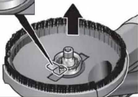
natural_image
Mechanical assembly diagram showing a tool interacting with a central component (no text or symbols visible)رأس الفرشاة
natural_image
Person using a power tool on a workbench (no text or symbols visible).7 que mi ziyada la fraglal yetlamas consn tjibh me spt
natural_image
Close-up of a mechanical component with no visible text or symbolsأعد تشغيل الجهاز
natural_image
Illustration of a hand using a power tool to cut or spread material on a workbench (no text or symbols visible)natural_image
Mechanical component diagram showing a rotating shaft with directional arrows and a plus sign (no text or symbols)أحكم ريط ذراع الشد.

natural_image
Close-up of a car's side panel showing a grille and vent, with directional arrows indicating movement (no text or symbols)natural_image
Cross-sectional diagram of a mechanical assembly (no visible text or labels)- ج CLK الطاء وبقايا #: Manufacturer: Manufacturer: Manufacturer: Manufacturer: Manufacturer: Manufacturer: Manufacturer: Manufacturer: Manufacturer: Manufacturer: Manufacturer: Manufacturer: Manufacturer: Manufacturer: Manufacturer: Manufacturer: Manufacturer: Manufacturer: Manufacturer: Manufacturer: Manufacturer: Manufacturer: Manufacturer: Manufacturer: Manufacturer: Manufacturer: Manufacturer: Manufacturer: Manufacturer: Manufacturer: Manufacturer: Manufacturer: Manufacturer: Manufacturer: Manufacturer: Manufacturer: Manufacturer: Manufacturer: Manufacturer: Manufacturer: Manufacturer: Manufacturer: Manufacturer: Manufacturer: Manufacturer: Manufacturer: Manufacturer: Manufacturer: Manufacturer: Manufacturer: Manufacturer :
الأرضيات.


- Inhalt
- Bürstenkranz
- Symbols used in this manual
- WARNING!
- CAUTION!
- NOTE
- Symbols on the device
- Important safety information
- Intended use
- Safety instructions
- Special safety notices for sanding/grinding
- Kickback and related safety notices
- Additional safety notices
- MATERIAL DAMAGE!
- Noise and vibration
- Overview
- Instructions for use
- Before initial operation
- Attaching and changing the abrading tool
- Adjusting the handle
- Adjusting the protective hood
- i NOTE
- Switching the power tool on/off Short-term operation without detent
- Non-stop operation with detent
- Speed preselection
- Using a dust extraction system
- Working with the power tool
- Replacing the protective hood
- Brush ring
- Rubber suction ring
- Maintenance and care
- Cleaning
- Repairs
- Spare parts and accessories
- Disposal information
- CE conformity
- Exemption from liability
- Table des matières
- Brosses en couronne
- Spazzola a corona
- Anillo cepillo
- Coroa de escovas
- Borstelkrans
- Børstekrans
- Borstkrans
- Harjareuna
- Στεφάνη βούρτσας
- Fırça kasnağı
- Wieniec szczotkowy
- Kartáčový věnec
- Kefový veniec
- Upute za uporabu
- Prije stavljanja u pogon
- Podešavanje ručke
- Zamjena štitnika
- Vijenac s četkama
- Neprekinjeno delovanje z uporabo prekucnega stikala
- i OPOMBA
- OPOMBA
- Krtačni venec
- Peria inelară
- Четков венец
- Венец из щеток
- Rõngashari
- Šepetinis žiedas
- Aizsargvāka maiņa
- Suku vainags
Brand : Flex
Model : LDE 16-8 125 R
Category : Grinder