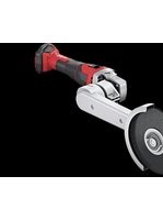
LD 15-10 125 - Grinder Flex - Free user manual and instructions
Find the device manual for free LD 15-10 125 Flex in PDF.

User questions about LD 15-10 125 Flex
0 question about this device. Answer the ones you know or ask your own.
Ask a new question about this device
Download the instructions for your Grinder in PDF format for free! Find your manual LD 15-10 125 - Flex and take your electronic device back in hand. On this page are published all the documents necessary for the use of your device. LD 15-10 125 by Flex.
USER MANUAL LD 15-10 125 Flex
natural_image
Illustration of two electric power tools with meshing and a flat disc (no text or symbols)de Originalbetriebsanleitung 3
en Original operating instructions 14
fr Notice d'instructions d'origine 24
it Istruzioni per l'uso originali 35
es Instrucciones de funcionamiento originales ..... 46
pt Instruções de serviço originais ..... 57
nl Originele gebruiksaanwijzing 68
da Originale driftsvejledning 79
no Originale driftsanvisningen 90
sv Originalbruksanvisning 100
fi Alkuperäinen käyttöohjekirja 109
el Auθεντικές οδηγίες χειρισμού 120
tr Orijinal işletme kılavuzu 132
pI Instrukcja oryginalna 143
hu Eredeti üzemeltetési útmutató 154
cs Originální návod k obsluze 165
sk Originálny návod na obsluhu 176
hr Originalna uputa za rad 187
sl Izvirno navodilo za obratovanje 198
ro Instructiuni de functionare originale 208
bg Оригинално упътване за експлоатация ..... 219
ru Оригинальная инструкция по эксплуатации ..... 230
et Originaalkasutusjuhend 242
It Originali naudojimo instrukcija 253
Iv Lietošanas pamācības oriģināls 264
ar إرشادات الأتشغيل الأصلية 283
Inhalt
Verwendete Symbole 3
Symbole am Gerät 3
text_image
Technical diagram of a power tool with numbered parts and labeled parts, including a dial indicator and workpiece details.text_image
Diagram showing a hand using a tool to adjust or install a mechanical component, labeled with numbers 1 and 2.natural_image
Close-up of a mechanical component with an arrow indicating direction, no visible text or symbolstext_image
Diagram showing a mechanical component with a downward arrow and directional symbol, likely illustrating a process or motion.text_image
"clic" 1. 2.natural_image
Close-up of a hand using a power tool on a textured surface (no text or symbols visible)text_image
Diagram showing two-step cleaning or repair process with numbered steps and directional arrownatural_image
Illustration of a hand using a power tool to cut or spread material on a workbench (no text or symbols visible)Symbols used in this manual ..... 14
Symbols on the power tool. 14
Important safety information ..... 14
Noise and Vibration 17
Technical specifications 17
Overview 18
Operating instructions ..... 19
Maintenance and care 22
Disposal information 22
C ∈-Declaration of Conformity ..... 22
Exemption from liability 23
Symbols used in this manual

WARNING!
Denotes impending danger. Non-observance of this warning may result in death or extremely severe injuries.

CAUTION!
Denotes a possibly dangerous situation. Non-observance of this warning may result in slight injury or damage to property.

NOTE
Denotes application tips and important information.
Symbols on the power tool

Before switching on the power tool, read the operating manual!

Wear goggles!

Disposal information for the old machine (see page 22)!
Important safety information

WARNING!
Before using the power tool, please read and follow:
– these operating instructions,
- the "General safety instructions" on the handling of power tools in the enclosed booklet (leaflet no.: 315.915),
– the currently valid site rules and the regulations for the prevention of accidents.
This power tool is state of the art and has been constructed in accordance with the acknowledged safety regulations. Nevertheless, when in use, the power tool may be a danger to life and limb of the user or a third party, or the power tool or other property may be damaged. The power tool may be operated only if it is
– used as intended,
– in perfect working order.
Faults which impair safety must be repaired immediately.
Intended use
The renovation sander LD 15-10 125 R / LD 15-10 125 / LDE 15-10 125 R is designed
– for commercial use in industry and trade,
– for dry sanding and smoothing of concrete, plaster, screed, sandstone, chamotte and asphalt,
– for grinding paintwork and adhesive residue off concrete or screed,
– for use with diamond-tipped tools which FLEX offers for this power tool and which are authorised to run at a speed of at least 10,000 r.p.m.
It is not permitted to use cutting-off wheels, roughing wheels, fan-like grinding wheels or wire brushes.
When using the renovation sander
LD 15-10 125 R / LD 15-10 125 /
LDE 15-10 125 R, connect a Class M dust extractor.
Safety instructions

WARNING!
Read all safety instructions and other instructions. Failure to observe the safety instructions and other instructions may result in an electric shock, fire and/or serious injuries. Keep all safety instructions and other instructions in a safe place for the future.
■ This power tool is intended to function as a grinder. Read all safety warnings, instructions, illustrations and specifications provided with this power tool.
Failure to follow all instructions listed below may result in electric shock, fire and/or serious injury.
■ Operations as sanding, wire brushing, polishing or abrasive cutting-off operations are not recommended to be performed with this power tool.
Operations for which the power tool was not designed may create a hazard and cause personal injury.
■ Do not use accessories which are not specifically designed and recommended by the tool manufacturer.
Just because the accessory can be attached to your power tool, it does not assure safe operation.
■ The rated speed of the accessory must be at least equal to the maximum speed marked on the power tool.
Accessories running faster than their rated speed can break and fly apart.
■ The outside diameter and the thickness of your accessory must be within the capacity rating of your power tool.
Incorrectly sized accessories cannot be adequately guarded or controlled.
■ The arbour size of wheels, flanges, backing pads or any other accessory must properly fit the spindle of the power tool.
Accessories with arbour holes that do not match the mounting hardware of the power tool will run out of balance, vibrate excessively and may cause loss of control.
■ Do not use a damaged accessory. Before each use inspect the accessory such as abrasive wheels for chips and cracks, backing pad for cracks, tear or excess wear, wire brush for loose or
cracked wires. If power tool or accessory is dropped, inspect for damage or install an undamaged accessory. After inspecting and installing an accessory, position yourself and bystanders away from the plane of the rotating accessory and run the power tool at maximum no-load speed for one minute.
Damaged accessories will normally break apart during this test time.
■ Wear personal protective equipment. Depending on application, use face shield, safety goggles or safety glasses. As appropriate, wear dust mask, hearing protectors, gloves and shop apron capable of stopping small abrasive or workpiece fragments.
The eye protection must be capable of stopping flying debris generated by various operations. The dust mask or respirator must be capable of filtrating particles generated by your operation. Prolonged exposure to high intensity noise may cause hearing loss.
- Keep bystanders a safe distance away from work area. Anyone entering the work area must wear personal protective equipment.
Fragments of workpiece or of a broken accessory may fly away and cause injury beyond immediate area of operation.
■ Hold power tool by insulated gripping surfaces only, when performing an operation where the cutting accessory may contact hidden wiring or its own cord.
Cutting accessory contacting a "live" wire may make exposed metal parts of the power tool "live" and shock the operator.
■ Position the cord clear of the spinning accessory.
If you lose control, the cord may be cut or snagged and your hand or arm may be pulled into the spinning accessory.
■ Never lay the power tool down until the accessory has come to a complete stop.
The spinning accessory may grab the surface and pull the power tool out of your control.
■ Do not run the power tool while carrying it at your side.
Accidental contact with the spinning accessory could snag your clothing, pulling the accessory into your body.
■ Regularly clean the power tool's air vents. The motor's fan will draw the dust inside the housing and excessive accumulation of powdered metal may cause electrical hazards.
■ Do not operate the power tool near flammable materials.
Sparks could ignite these materials.
■ Do not use accessories that require liquid coolants.
Using water or other liquid coolants may result in electrocution or shock.
Special safety instructions for grinding
■ Wheels must be used only for recommended applications.
For example: do not grind with the side of cut-off wheel.
Abrasive cut-off wheels are intended for peripheral grinding, side forces applied to these wheels may cause them to shatter.
■ Always use undamaged wheel flanges that are of correct size and shape for your selected wheel. Proper wheel flanges support the wheel thus reducing the possibility of wheel breakage.
Flanges for cut-off wheels may be different from grinding wheel flanges.
■ Do not use worn down wheels from larger power tools.
Wheel intended for larger power tool is not suitable for the higher speed of a smaller tool and may burst.
Kickback and Related Warnings
Kickback is a sudden reaction to a pinched or snagged rotating wheel, backing pad, brush or any other accessory. Pinching or snagging causes rapid stalling of the rotating accessory which in turn causes the uncontrolled power tool to be forced in the direction opposite of the accessory's rotation at the point of the binding. For example, if an abrasive wheel is snagged or pinched by the workpiece, the edge of the wheel that is entering into the pinch point can dig into the surface of the material causing the wheel to climb out or kick out. The wheel may either jump toward or away from the operator, depending on direction of the wheel's movement at the point of pinching. Abrasive wheels may also break under these conditions.
Kickback is the result of power tool misuse and/or incorrect operating procedures or conditions and can be avoided by taking proper precautions as given below.
- Maintain a firm grip on the power tool and position your body and arm to allow you to resist kickback forces. Always use auxiliary handle, if provided, for maximum control over kickback or torque reaction during start-up.
The operator can control torque reactions or kickback forces, if proper precautions are taken.
■ Never place your hand near the rotating accessory. Accessory may kickback over your hand.
■ Do not position your body in the area where power tool will move if kickback occurs.
Kickback will propel the tool in direction opposite to the wheel's movement at the point of snagging.
■ Use special care when working corners, sharp edges etc. Avoid bouncing and snagging the accessory.
Corners, sharp edges or bouncing have a tendency to snag the rotating accessory and cause loss of control or kickback.
■ Do not attach a saw chain, woodcarving blade or toothed saw blade.
Such blades create frequent kickback and loss of control.
Additional safety instructions
■ Use only extension cables permitted for outdoor use.
■ It is not recommended to sand lead paint. Lead paint should be removed by a specialist only.
■ Do not grind or cut materials which release hazardous substances (e.g. asbestos). Take precautions if hazardous, combustible or explosive dust is likely to occur. Wear protective dust mask.
Use dust extraction system.

DAMAGE TO PROPERTY!
■ The mains voltage and the voltage specifications on the rating plate must correspond.
Noise and Vibration
The noise and vibration values have been determined in accordance with EN 60745.
The A evaluated noise level of the power tool is typically:
– Sound pressure level: 87.3 dB(A);
– Sound power level: 98.3 dB(A);
- Uncertainty: K = 3 dB.
Total vibration value (when sanding concrete areas):
- Emission value: a _h=6.4m^2/s
- Uncertainty: K = 1.5 m/s

Attention
The indicated measurements refer to new power tools. Daily use causes the noise and vibration values to change.

NOTE
The vibration emission level given in this information sheet has been measured in accordance with a standardised test given in EN 60745 and may be used to compare one tool with another. It may be used for a preliminary assessment of exposure. The declared vibration emission level represents the main applications of the tool.
However if the tool is used for different applications, with different accessories or poorly maintained, the vibration emission may differ. This may significantly increase the exposure level over the total working period
For a precise estimation of the vibration load the times should also be considered during which the power tool is switched off or even running, but not actually in use. This may significantly increase the exposure level over the total working period Identify additional safety measures to protect the operator from the effects of vibration such as: maintain the tool and the accessories, keep the hands warm, organisation of work patterns.

CAUTION!
Wear ear protection at a sound pressure above 85 dB(A).
Technical specifications
| LD 15-10 125 R L | D 15-10 125 LD | E 15-10 125 R | ||
| Machine type Renovation sander | ||||
| Mains voltage V/Hz 230/50 | ||||
| Protection class | II / ☐ | |||
| Power input W | 1,450 | |||
| Speed | r.p.m. | 10,000 | 4,000-10,000 | |
| Rated speed | r.p.m. | 11,700 | ||
| Tool holder | M14 | |||
| Max. disc diameter | mm | 125 | ||
| Weight (without power cord) | kg | 2.9 | 3.2 | 2.9 |
Overview
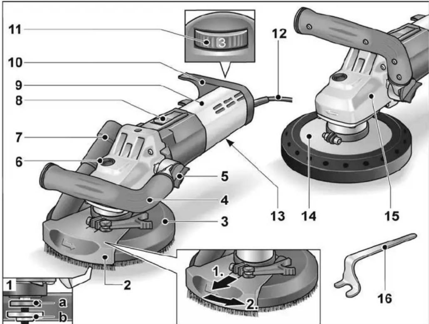
text_image
Technical diagram of a power tool with numbered parts and labeled parts in Chinese1 Spindle with threaded flange
a Clamping flange
b Clamping nut
2 Pivoted edge segment
3 Guard hood with brush ring
(LD 15-10 125 R / LDE 15-10 125 R)
4 Handle, adjustable
5 Rotary knob for adjusting the handle
6 Spindle lock
Secures the spindle when the tool is changed.
7 Connection for extractor
8 Switch rocker
Switches the power tool on and off.
With notched position for continuous operation.
9 Rear handle/housing
10 Hose support
11 Dial for preselecting the speed (LDE 15-10 125 R)
12 4.0 m power cord with mains plug
13 Rating plate
14 Guard with rubber extraction ring (LD 15-10 125)
15 Gear head
With air outlet and direction-of-rotation arrow.
16 Stop key
Operating instructions
Before switching on the power tool Unpack power tool and accessories and check that no parts are missing or damaged.
Inserting and changing the sanding tools
WARNING!
Before performing any work on the electric power tool, pull out the mains plug.
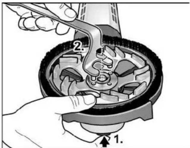
text_image
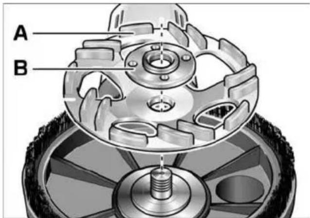
Diagram showing a hand operating a mechanical component with labeled parts 1 and 2, likely illustrating a turning or disassembly process.■ Press and hold down the spindle lock (1.).
■ Using the stop key, loosen the clamping nut on the spindle in an anti-clockwise direction and remove (2.).
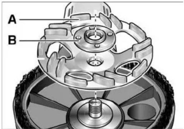
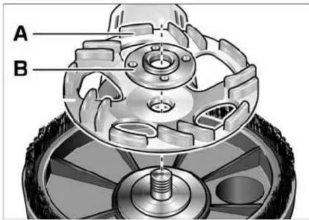
■ Insert diamond sanding pad (A) correctly.
text_image
A B■ Screw the clamping nut (B), with flange face up, onto the spindle.
■ Press and hold down the spindle lock.
■ Tighten the clamping nut with the stop key.
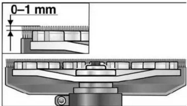
■ LD 15-10 125 R / LDE 15-10 125 R: Check position of the guard.

text_image
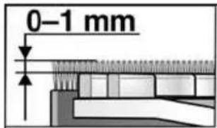
0-1 mmThe brush ring should protrude over the sanding pad by approx. 0–1 mm. If required, correct (see "Adjusting the guard (LD 15-10 125 R / LDE 15-10 125 R)").
■ Insert the mains plug into the socket.
■ Switch on the electric power tool (without locking the button) and leave it running for approx. 30 seconds. Check for imbalances and vibrations.
■ Switch off the electric power tool.
Adjusting the handle
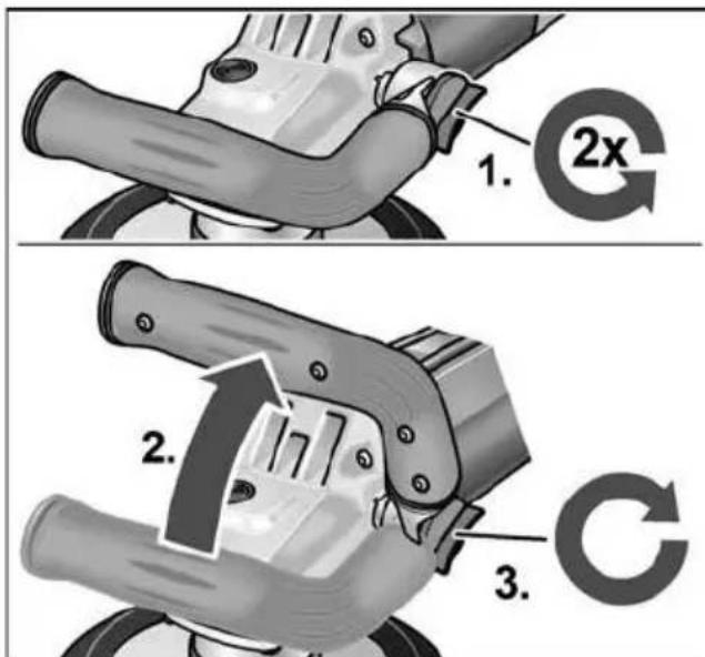
text_image
1. 2x 2. 3.■ Loosen rotary knob for adjusting the handle by turning it approx. 2 revolutions anti-clockwise.
■ Place handle in the required position (15° notch).
Ensure that handle engages correctly!
■ Tighten rotary knob for adjusting the handle clockwise.
i NOTE
If required, the handle can be moved to the other side of the electric power tool.
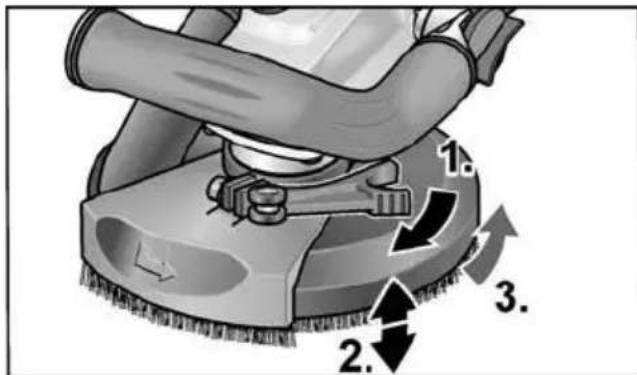
Adjusting the guard (LD 15-10 125 R / LDE 15-10 125 R)
i NOTE
The brush ring should protrude over the sanding pad by approx. 0–1 mm.
To compensate for wear on the diamond sanding pad, the height of the guard can be adjusted.
■ Loosen clamping lever on guard hood.
■ Set the guard hood to the required height.
text_image
Diagram of a cleaning or cleaning machine with numbered steps and directional arrows indicating process flow.■ Tighten the clamping lever.
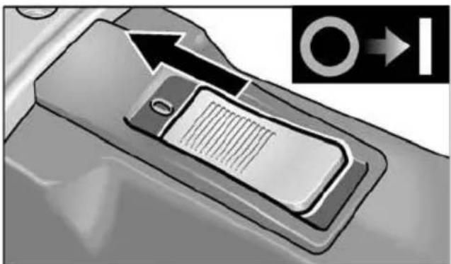
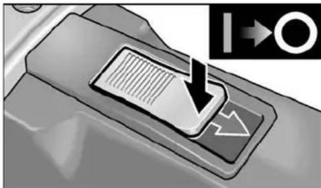
Switching the electric power tool on and off
Brief operation without engaged switch rocker
natural_image
Diagram of a vehicle door handle with an arrow indicating direction and a circular symbol (no text or labels)■ Push the switch rocker forwards and hold in position.
■ To switch off the power tool, release the switch rocker.
Continuous operation with engaged switch rocker

text_image
1. 2.■ Push the switch rocker forwards and engage by pressing the front end.
i NOTE
Following a power failure, the switched on power tool does not restart.
Switch off the machine:
natural_image
Close-up of a car's air vent with a filter and directional arrow indicator (no text or symbols)■ To switch off the power tool, release the switch rocker by pressing the rear end.
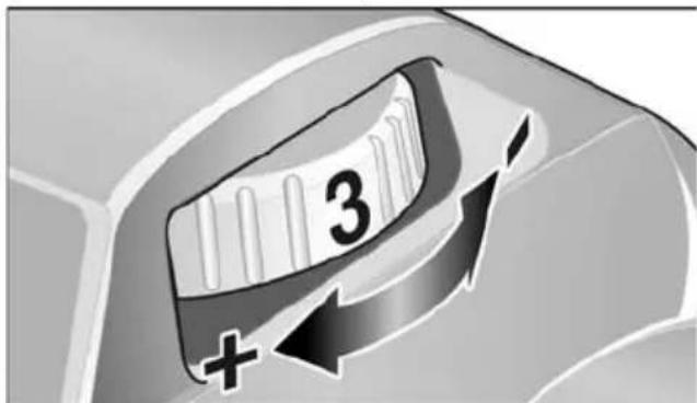
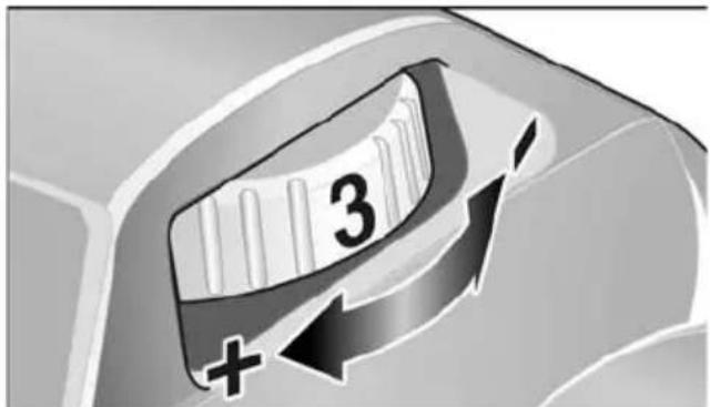
Preselecting the speed (LDE 15-10 125 R)
text_image
3 +■ To set the operating speed, move the dial to the required value.
CAUTION!
Risk of injury due to destruction of the tool. Use the appropriate tool for the job.
NOTE
Avoid exerting excess pressure on the tool when sanding/grinding at low speed (1-3) as otherwise it will quickly overheat.
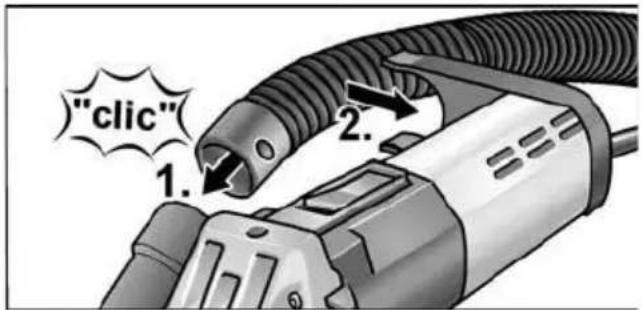
Using a dust extraction system
i NOTE
It is recommended to use a FLEX Class M dust extractor.
■ Connect extraction hose to the 32 mm connector.
■ Engage extraction hose in hose support.
text_image
"click" 1. 2.■ Connect extraction hose to the dust extraction system. Follow the operating instructions for the dust extraction system! Check the attachment! If required, use an appropriate adapter.
i NOTE
If your dust extractor requires a special connection (i.e. a connection other than the 32 mm/36 mm standard connection which is included with the electric power tool), contact your dust extractor supplier to obtain the appropriate adapter.
Working with the power tool
WARNING!
The rotating sanding disc must not come into contact with sharp projecting objects. Danger of kickback! Damage to sanding pad. If the sanding pad is damaged or severely worn, it must be replaced.
CAUTION!
Hold the electric power tool with both hands!
- Attach sanding tool.
- Connect dust extraction system.
- Insert mains plug.
- Switch on dust extraction system.
-
Switch on the device.
-
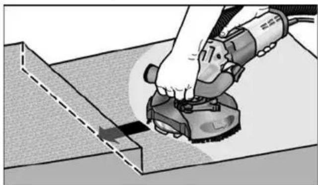
Place the renovation sander on the work surface.
The brush ring (LD 15-10 125 R / LDE 15-10 125 R) or the rubber extraction ring (LD 15-10 125) must be flush with the work surface.

natural_image
Illustration of a hand using a power tool on a workbench (no text or symbols visible)-
Increase the pressure to bring the sanding pad into contact with the work surface. In doing so, slew the renovation sander with overlapping movements.
-
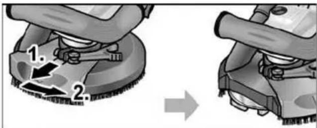
Sanding in corners (LD 15-10 125 R / LDE 15-10 125 R):
-
Switch off the power tool and wait until the sanding tool has come to a standstill.
– Pull out pivoted edge segment and swivel to left.
text_image
1. 2.- Switch on power tool again.
natural_image
Illustration of a hand using a power tool to cut a metal sheet (no text or symbols visible)- After work, switch off the electric power tool and pull out the mains plug.
Brush ring (LD 15-10 125 R / LDE 15-10 125 R)
The guard features a brush ring. This ring has two functions:
- As the ring projects above the surface of the sanding pad, it is the ring which comes into contact with the work surface first. As a result, the sanding pad is brought parallel to the work surface before the sanding tool comes into contact with the work surface. This avoids a sickle-shaped depression caused by the edge of the sanding pad.
- The ring retains the dust until it is extracted by the dust extractor.
If the brush ring is damaged or excessively worn, it should be replaced.
A replacement brush set is available from any FLEX-customer service centre.
Rubber extraction ring (LD 15-10 125)
If the rubber extraction ring is damaged or excessively worn, it should be replaced. A replacement extraction ring is available from any FLEX customer service centre.
Maintenance and care

WARNING!
Before performing any work on the electric power tool, pull out the mains plug.
Cleaning

WARNING!
Do not use water or liquid detergents.
■ Regularly blow out the housing interior and motor with dry compressed air.
■ Clean the guard and pivoted edge segment using dry compressed air.
Repairs
Repairs may be carried out by an authorised customer service centre only.

NOTE
During the warranty period do not loosen the screws on the motor housing. Non-compliance will deem the guarantee obligations of the manufacturer null and void.
Spare parts and accessories
Other accessories, in particular insertion tools, can be found in the manufacturer's catalogues.
Exploded drawings and spare-part lists can be found on our homepage:
www.flex-tools.com
Disposal information

WARNING!
Render redundant power tools unusable by removing the power cord.

EU countries only
Do not throw electric power tools into the household waste!
In accordance with the European
Directive 2012/19/EU on Waste Electrical and Electronic Equipment and transposition into national law used electric power tools must be collected separately and recycled in an environmentally friendly manner.

NOTE
Please ask your dealer about disposal options!
CE-Declaration of Conformity
We declare under our sole responsibility that the product described under “Technical specifications” conforms to the following standards or normative documents:
EN 60745 in accordance with the regulations of the directives 2014/30/EU, 2006/42/EC, 2011/65/EU.
Responsible for technical documents: FLEX-Elektrowerkzeuge GmbH, R & D Bahnhofstrasse 15, D-71711 Steinheim/Murr


text_image
Bolts -1Manager Research & Development (R & D)
Klaus Peter WeinperEckhard F
Head of Quality
Department (QD)
22.05.2018
Exemption from liability
The manufacturer and his representative are not liable for any damage and lost profit due to interruption in business caused by the product or by an unusable product. The manufacturer and his representative are not liable for any damage which was caused by improper use of the power tool or by use of the power tool with products from other manufacturers.
Table des matières
text_image
Technical diagram of a power tool with numbered parts and labeled parts, including a 16-pin wrench and a 3-pin dial.text_image
Diagram showing a hand using a tool to adjust or install a mechanical component, labeled with numbers 1 and 2.natural_image
Close-up of a mechanical component with an arrow indicating direction, no visible text or symbolstext_image
Diagram showing a car's side panel with a downward arrow and directional arrows, indicating a process or movement.text_image
"click" 1. 2.natural_image
Illustration of a hand using a power tool on a textured surface (no text or symbols visible)text_image
Diagram showing two-step cleaning or repair process with numbered steps and directional arrownatural_image
Illustration of a hand using a power tool to cut or spread material on a workbench (no text or symbols visible)text_image
Bikks Q - 1Manager Research & Development (R & D)
Head of Quality Department (QD)
22.05.2018
text_image
Technical diagram of a power tool with numbered parts and labeled parts in Chinesetext_image
Diagram showing a hand using a tool to adjust or install a mechanical component, labeled with numbers 1 and 2.natural_image
Cross-sectional diagram of a mechanical assembly (no text or labels visible)text_image
Diagram of a cleaning or cleaning machine with numbered steps and directional arrows indicating process flow.natural_image
Close-up of a mechanical component with an arrow indicating direction, no visible text or symbolsnatural_image
Close-up of a car's front panel with a black arrow pointing to a textured surface and an arrow pointing to a circle (no text or symbols visible)text_image
"click" 1. 2.natural_image
Illustration of a hand using a power tool to clean or repair a surface (no text or symbols visible)natural_image
Illustration of a hand using a power tool to cut or spread material on a workbench (no text or symbols visible)text_image
Technical diagram of a power tool with numbered parts and labeled parts in Chinesetext_image
Diagram illustrating a mechanical assembly process with labeled parts and directional arrowsnatural_image
Close-up of a mechanical component with an arrow indicating direction, showing internal structure and a circular symbol (no text or labels)text_image
Diagram showing a mechanical component with a downward arrow and directional symbol, likely illustrating a process or motion.text_image
"click" 1. 2.natural_image
Illustration of a hand using a power tool to clean or repair material on a textured surface (no text or symbols visible)natural_image
Illustration of a hand using a power tool to cut or spread material on a workbench (no text or symbols visible)text_image
Bolts Q - 1Manager Research & Development (R & D)
Klaus Peter WeinperEckhard F Head of Quality Department (QD)
22.05.2018
text_image
Technical diagram of a power tool with numbered parts and labeled parts in Chinesetext_image
Diagram showing a hand using a tool to adjust or install a mechanical component, labeled with numbers 1 and 2.natural_image
Close-up of a mechanical component with an arrow indicating direction and a circular symbol (O→I) in the corner, no readable text or symbols present.natural_image
Close-up of a car's front panel with a black arrow pointing to a textured surface and an arrow pointing to a circle (no text or symbols visible)text_image
"click" 1. 2.natural_image
Close-up of a hand using a power tool on a workbench (no text or symbols visible)natural_image
Illustration of a hand using a power tool to cut or spread material on a workbench (no text or symbols visible)EN 60745 de acordo com as determinações das directivas 2014/30/UE, 2006/42/CE, 2011/65/UE.
text_image
Technical diagram of a power tool with numbered parts and labeled parts, including a 3D control knob and a 16-pin wrench.text_image
Diagram illustrating a mechanical assembly process with labeled parts and directional arrowsnatural_image
Close-up of a car door handle with a slot and arrow indicator (no text or symbols)natural_image
Close-up of a car's front panel with a black arrow pointing to a textured surface and an arrow pointing to a circle (no text or symbols)text_image
"click" 1. 2.natural_image
Illustration of a hand using a power tool on a workbench (no text or symbols visible)natural_image
Illustration of a hand using a power tool to cut or spread material on a workbench (no text or symbols visible)text_image
Technical diagram of a power tool with numbered parts and labeled parts in Chinesetext_image
Diagram showing mechanical assembly steps with numbered labels 1 and 2 indicating different states or components.natural_image
Close-up of a mechanical component with an arrow indicating direction, no visible text or symbols■ Skub vippekontakten fremad og hold den fast.
■ Slip vippekontakten for at slukke.
natural_image
Close-up of a car's front panel with a black arrow pointing to a textured surface and an arrow pointing to a circle (no text or symbols visible)■ Frigør vippekontakten ved at trykke på bagerste ende for at slukke.
text_image
"click" 1. 2.natural_image
Illustration of a hand using a power tool on a textured surface (no text or symbols visible)natural_image
Illustration of a hand using a power tool to cut or spread material on a workbench (no text or symbols visible)text_image
Handwritten signature or scribble with a circular arrow-like shape above it, possibly a signature or annotation.Manager Research & Development (R & D)
Klaus Peter WeinperEckhard F Head of Quality Department (QD)
22.05.2018
text_image
Technical diagram of a power tool with numbered parts and labeled parts, including a 3D control knob and a 16-pin workpiece.text_image
Diagram showing a hand using a tool to adjust or install a mechanical component, labeled with numbers 1 and 2.text_image
Diagram of a cleaning or cleaning machine with numbered steps and directional arrows indicating process flow.■ Trekk spennspaken fast.
natural_image
Close-up of a mechanical component with an arrow indicating direction, showing internal structure and a circular symbol (no text or labels)text_image
Diagram showing a mechanical component with directional arrow and symbol, likely illustrating a process or motion direction.text_image
"click" 1. 2.■ Avsugingsslangen tilkoples til avsugingsanlegget. Ta hensyn til betjeningsveiledningen for avsugingsanlegget! Kontroller festet! Om nødvendig må det brukes en passende adapter.
i
HENVISNING
natural_image
Illustration of a hand using a power tool on a tiled floor (no text or symbols visible)natural_image
Illustration of a hand using a power tool to cut or spread material on a workbench (no text or symbols visible)Manager Research & Development (R & D)
Klaus Peter WeinperEckhard F Head of Quality Department (QD)
22.05.2018
text_image
Technical diagram of a power tool with numbered parts and labeled parts in Chinesetext_image
Diagram showing mechanical assembly steps with numbered labels 1 and 2 indicating different states or components.natural_image
Close-up of a car door handle with a slot and arrow indicator (no text or symbols)text_image
Diagram showing a mechanical component with directional arrow and symbol, likely illustrating a process or motion direction.text_image
"click" 1. 2.natural_image
Illustration of a hand using a power tool on a textured surface (no text or symbols visible)natural_image
Illustration of a hand using a power tool to cut or spread material on a workbench (no text or symbols visible)Manager Research & Development (R & D)
Head of Quality Department (QD)
text_image
Technical diagram of a power tool with numbered parts and labeled parts in Chinese1 Kara, jossa kierrelaippa
a Kiinnityslaippa
b Kiinnitysmutteri
text_image
Diagram showing mechanical assembly with labeled parts and directional arrows, likely illustrating a turning or disassembly process.text_image
Diagram of a cleaning or cleaning tool with numbered arrows indicating motion stepsnatural_image
Mechanical component with arrow indicating direction, no visible text or symbolstext_image
Diagram showing a mechanical component with a downward arrow and directional symbol, likely illustrating a process or motion.text_image
"click" 1. 2.natural_image
Illustration of a hand using a power tool on a workbench (no text or symbols visible)natural_image
Illustration of a hand using a power tool to cut or spread material on a workbench (no text or symbols visible)text_image
Handwritten signature or scribble with partial text and a curved line, possibly from a document or form.Manager Research & Development (R & D)
Klaus Peter WeinperEckhard F
22.05.2018
Head of Quality
Department (QD)
text_image
Technical diagram of a power tool with numbered parts and labeled parts, including a 3D control knob and a 16-pin wrench.text_image
Diagram showing a hand using a tool to adjust or install a mechanical component, labeled with numbers 1 and 2.natural_image
Close-up of a mechanical component with an arrow indicating direction, showing internal structure and a circular symbol (no text or labels)natural_image
Close-up of a car's front panel with a black arrow pointing to a textured surface and directional arrows (no text or symbols)text_image
"click" 1. 2.natural_image
Person using a power tool on a tiled floor (no text or symbols visible)natural_image
Illustration of a hand using a power tool to cut or spread material on a workbench (no text or symbols visible)text_image
Handwritten signature or scribble with partial text and a curved line, likely from a document or form.Klaus Peter WeinperEckhard F
Manager Research & Development (R & D)
Head of Quality Department (QD)
22.05.2018
text_image
Technical diagram of a power tool with numbered parts and labeled parts, including a 3D control knob and a 16-pin wrench.1 Vida dişli flanşlı mil
a Sıkma flanşı
b Germe somunu
text_image
Diagram showing a hand using a tool to adjust or install a mechanical component, labeled with numbers 1 and 2.natural_image
Close-up of a mechanical component with an arrow indicating direction, no visible text or symbolsnatural_image
Close-up of a mechanical component with a black arrow pointing to a textured surface and an arrow pointing to a circle (no text or symbols visible)text_image
"click" 1. 2.natural_image
Close-up of a hand using a power tool to clean or apply material on a textured surface (no text or symbols visible)natural_image
Illustration of a hand using a power tool to cut or spread material on a cutting board (no text or symbols visible)Manager Research & Development (R & D)
Head of Quality
Department (QD)
22.05.2018
text_image
Technical diagram of a power tool with numbered parts and labeled parts, including a dial indicator and cleaning tools.text_image
Diagram showing a hand using a tool to adjust or install a mechanical component, labeled with numbers 1 and 2.natural_image
Close-up of a mechanical component with an arrow indicating direction and a symbol (O→I) in the corner, no readable text or labels present.text_image
Diagram showing a device control panel with an arrow pointing to a circular symbol, alongside a directional indicator labeled 'I→O'.text_image
"click" 1. 2.natural_image
Illustration of a hand using a power tool to clean or repair a surface (no text or symbols visible)text_image
Diagram showing two-step cleaning process of a mounted machine, labeled with steps 1 and 2.natural_image
Illustration of a hand using a power tool to cut or spread material on a cutting board (no text or symbols visible)text_image
Bolts Q - 1Klaus Peter WeinperEckhard F Head of Quality Department (QD)
Manager Research & Development (R & D) 22.05.2018
text_image
Technical diagram of a power tool with numbered parts and labeled parts, including a 3D control knob and a 16-pin wrench.1 Orsó menetes peremmel
Szorító perem
Szorító anya
text_image
Diagram illustrating a mechanical assembly process with labeled parts and directional arrowsnatural_image
Close-up of a car door handle with a slot and arrow indicator (no text or symbols)text_image
Diagram showing a device with a grid and directional arrow, labeled with 'I→O' in the corner.text_image
"click" 1. 2.natural_image
Illustration of a hand using a power tool on a textured surface (no text or symbols visible)text_image
Diagram showing two-step installation of a mechanical component with labeled parts and directional arrownatural_image
Illustration of a hand using a power tool to cut or spread material on a workbench (no text or symbols visible)text_image
Bolts Q - 1Manager Research & Development (R & D)
Klaus Peter WeinperEckhard F
Head of Quality Department (QD
22.05.2018
text_image
Technical diagram of a power tool with numbered parts and labeled parts, including a dial indicator and cleaning tools.text_image
Diagram showing a hand using a tool to adjust or install a mechanical component, labeled with numbers 1 and 2.natural_image
Close-up of a car door handle with a slot and arrow indicator (no text or symbols)text_image
Diagram showing a device's internal structure with directional arrow and circular symbol, likely illustrating a process or control mechanism.text_image
"clic" 1. 2.natural_image
Illustration of a hand using a power tool on a tiled floor (no text or symbols visible)natural_image
Illustration of a hand using a power tool to cut or spread material on a workbench (no text or symbols visible)Manager Research & Development (R & D)
Klaus Peter WeinperEckhard F Head of Quality Department (QD)
22.05.2018
text_image
Technical diagram of a power tool with numbered parts and labeled parts, including a dial indicator and workpiece details.text_image
Diagram showing a hand using a tool to adjust or install a mechanical component, labeled with numbers 1 and 2.text_image
Diagram of a cleaning or cleaning machine with numbered arrows indicating motion steps■ Upínaciu páku pevne utiahnite.
natural_image
Close-up of a car door handle with a slot and arrow indicator (no text or symbols)natural_image
Close-up of a car's front panel with a black arrow pointing to a textured surface and an arrow pointing to a circle (no text or symbols visible)text_image
"click" 1. 2.natural_image
Illustration of a hand using a power tool on a workbench (no text or symbols visible)natural_image
Illustration of a hand using a power tool to cut or spread material on a workbench (no text or symbols visible)text_image
Bolts Q - 1Manager Research & Development (R & D)
Klaus Peter WeinperEckhard F
Head of Quality
Department (QD)
22.05.2018
text_image
Technical diagram of a power tool with numbered parts and labeled parts, including a dial indicator and cleaning tools.1 Vreteno s prirubnicom s navojem
a Stezna prirubnica
b Stezna matica
2 Zakretni rubni segment
3 Štitnik s vijencem s četkama
(LD 15-10 125 R / LDE 15-10 125 R)
4 Ručka, podesiva
5 Okretni gumb za podešavanje ručke
6 Zavor vretena
Za utvrdjivanje vretena pri zamjeni alata.
7 Priključak za nastavak za usisavanje
8 Ozibna sklopka
Za uključivanje i isključivanje.
Sa stojnim položajem za trajni rad.
text_image
Diagram showing a hand using a tool to adjust or install a mechanical component, labeled with numbers 1 and 2.■ Pritisnite blokadu vretena i držite je pritisnutu (1.).
■ Otpustite steznu maticu s vretena pomoću zaustavnog ključa u smjeru suprotnom od kazaljke na satu i skinite je (2.).
■ Dijamantni brusni tanjur (A) umetnite u ispravnom položaju.
text_image
A B■ Steznu maticu (B) s vijencem okrenutim prema gore uvrnite na vreteno.
■ Pritisnite blokadu vretena i držite je pritisnutu.
■ Steznu maticu zategnite zaustavnim ključem.
■ LD 15-10 125 R / LDE 15-10 125 R: Provjerite položaj štitnika.
text_image
0-1 mmVijenac s četkama trebao bi stršati preko brusnog tanjura oko 0–1 mm. Po potrebi ispravite (pogledajte „Namještanje štitnika (LD 15-10 125 R / LDE 15-10 125 R)“).
■ Utaknite mrežni utikač u utičnicu.
■ Uključite električni alat (bez uglavljivanja) i ostavite ga da radi otprilike 30 sekundi. Provjerite dolazi li do neuravnoteženosti i vibracija.
■ Isključite električni alat.
Podešavanje ručke

text_image
1. 2x 2. 3.■ Okretni gumb za podešavanje ručke otpustite za oko 2 okretaja u smjeru suprotnom od kazaljke na satu.
■ Stavite ručku u željeni položaj (urez od 15°). Pazite na ispravno uglavljivanje!
natural_image
Close-up of a mechanical component with an arrow indicating direction, no visible text or symbolstext_image
Diagram showing a device control panel with an arrow pointing to a circular symbol, alongside a directional indicator labeled 'I→O'.■ Radi isključivanja ozibnu sklopku deblokirati pritiskom na zadnji kraj.
Predodabir broja okretaja (LDE 15-10 125 R)
text_image
3 +text_image
"click" 1. 2.natural_image
Illustration of a hand using a power tool on a tiled floor (no text or symbols visible)natural_image
Illustration of a hand using a power tool to cut or spread material on a workbench (no text or symbols visible)- Po završetku rada isključite električni alat i izvucite mrežni utikač.
Vijenac s četkama (LD 15-10 125 R / LDE 15-10 125 R)
Manager Research & Development (R & D)
Klaus Peter WeinperEckhard Rühle Head of Quality Department (QD)
22.05.2018
Hrup in tresljaji 201
- Negotovost: K = 3 dB.
- Zvočni tlak: 87,3 dB(A); - Zvočna moč: 98,3 dB(A); - Negotovost: K = 3 dB.
Skupna vrednost tresljajev (pri brušenju betonskih površin):
- Emisijska vrednost: a _h = 6,4m^2/s
- Negotovost: K = 1,5 m/s
- Emisijska vrednost: a _h=6,4m^2/s - Negotovost: K=1,5 m/s

POZOR!
text_image
Technical diagram of a power tool with numbered parts and labeled parts, including a dial indicator and cleaning tools.text_image
Diagram showing mechanical assembly steps with numbered labels 1 and 2 indicating different states or components.■ Pritisnite in držite zaporo vretena (1.).
■ Z zadrževalnim ključem zavrtite vpenjalno matico v levo in jo snemite z vretena (2.).
■ Pravilno namestite diamantni brusilni krožnik (A).
text_image
A B■ Vpenjalno matico (B) privijte na vreteno tako, da bo podaljšek matice obrnjen navzgor.
■ Pritisnite in držite zaporo vretena.
■ Vpenjalno matico zategnite z zadrževalnim ključem.
■ LD 15-10 125 R / LDE 15-10 125 R: Bodite pozorni na položaj zaščitnega pokrova.
text_image
0-1 mm
natural_image
Cross-sectional diagram of a mechanical assembly (no text or labels visible)natural_image
Close-up of a mechanical component with an arrow indicating direction, no visible text or symbols■ Prekucno stikalo potisnite naprej in ga pridržite.
■ Za izklop prekucno stikalo izpustite.
Neprekinjeno delovanje z uporabo prekucnega stikala

text_image
1. 2.■ Prekucno stikalo potisnite naprej in ga s pritiskom na sprednji del zaskočite.
i OPOMBA
text_image
Diagram showing a car door handle with a black arrow pointing to a circular symbol, alongside an icon indicating direction.■ Za izklop pritisnite na zadnji del prekucnega stikala, tako da sprostite zaporo.
text_image
"clic" 1. 2.■ Sesalno cev priključite na sesalnik. Upoštevajte navodila za uporabo sesalnika! Preverite, ali je cev dobro pritrjena! Po potrebi uporabite ustrezen adapter.

OPOMBA
Če boste za svoj sesalnik potrebovali poseben nastavek (tj. nastavek, ki se razlikuje od priloženega 32/36-milimetrskega standardnega nastavka), stopite v stik s svojim dobaviteljem sesalnikov, pri katerem boste prejeli primeren adapter.
natural_image
Illustration of a hand using a power tool on a tiled floor (no text or symbols visible)-
Povečajte silo, da brusilni krožnik pride v stik z delovno površino. Ob tem obrnite brusilnik za sanacije s prekrivajočimi gibi.
-
Za brušenje v kotih (LD 15-10 125 R / LDE 15-10 125 R):
– Izklopite orodje in počakajte, da se brusilni nastavek ustavi.
– Izvlecite pomični robni segment in ga obrnite v levo.

text_image
1. 2.– Znova vklopite orodje.
natural_image
Illustration of a hand using a power tool to cut or spread material on a workbench (no text or symbols visible)- Po končanem delu izklopite električno orodje in izvlecite vtič iz vtičnice.
Krtačni venec (LD 15-10 125 R / LDE 15-10 125 R)
Manager Research & Development (R & D)
Klaus Peter WeinperEckhard F Head of Quality Department (QD)
22.05.2018
text_image
Technical diagram of a power tool with numbered parts and labeled parts, including a 3D control knob and a 16-pin wrench.text_image
Diagram showing a mechanical assembly with labeled parts, including a tool and numbered callouts.natural_image
Close-up of a car interior component with a handle and internal structure, no visible text or symbolsnatural_image
Close-up of a mechanical component with a black arrow pointing to a textured surface and an arrow pointing to a circle (no text or symbols visible)text_image
"click" 1. 2.natural_image
Close-up of a hand using a power tool to clean or work on a textured surface (no text or symbols visible)text_image
Diagram showing two-step installation of a mechanical component with labeled parts and directional arrownatural_image
Illustration of a hand using a power tool to cut or spread material on a workbench (no text or symbols visible)Conform Directivei Europene
Directivei 2014/30/UE, 2006/42/CE,
2011/65/UE.
text_image
Bolivia -1Manager Research &
Development (R & D)
22.05.2018
text_image
Technical diagram of a power tool with numbered parts and labeled parts, including a dial indicator and cleaning tools.text_image
Diagram showing a hand using a tool to adjust or install a mechanical component, labeled with numbers 1 and 2.text_image
Diagram of a cleaning or cleaning device with numbered steps and directional arrows indicating process flow.natural_image
Close-up of a car's side panel with a handle and internal slot, showing directional arrow and symbol (no readable text or labels)text_image
Diagram showing a device with a black arrow pointing to a button labeled 'I→O', indicating direction or process flow.text_image
"click" 1. 2.natural_image
Close-up of a hand using a power tool to clean or work on a textured surface (no text or symbols visible)natural_image
Illustration of a hand using a power tool to cut or spread material on a workbench (no text or symbols visible)text_image
Bolts Q - 1Klaus Peter WeinperEckhard F
Manager Research & Development (R & D)
Head of Quality Department (QD)
22.05.2018
text_image
Technical diagram of a power tool with numbered parts and labeled parts, including a dial indicator and cleaning tools.text_image
Diagram illustrating a mechanical assembly process with labeled parts and directional arrowsnatural_image
Diagram of a vehicle door handle with internal components and directional arrow (no text or symbols)natural_image
Close-up of a mechanical component with a black arrow pointing to a textured surface and an arrow indicating direction (no text or symbols)text_image
"click" 1. 2.natural_image
Illustration of a hand using a power tool to clean or repair a surface (no text or symbols visible)natural_image
Illustration of a hand using a power tool to cut or spread material on a workbench (no text or symbols visible)text_image
Bolts Q - 1Klaus Peter WeinperEckhard F
Manager Research & Development (R & D)
Head of Quality Department (QD)
text_image
Technical diagram of a power tool with numbered parts and labeled parts, including a 16-pin wrench and a 3-pin dial.text_image
Diagram illustrating a mechanical assembly process with labeled parts and directional arrowstext_image
Diagram of a cleaning or cleaning machine with numbered steps and directional arrows indicating process flow.■ Tõmmata kinnitushoob kinni.
natural_image
Close-up of a mechanical component with an arrow indicating direction, no visible text or symbolsnatural_image
Close-up of a car's front panel with a black arrow pointing to a textured surface and an arrow pointing to the right (no text or symbols visible)text_image
"click" 1. 2.natural_image
Illustration of a hand using a power tool on a textured surface (no text or symbols visible)natural_image
Illustration of a hand using a power tool to cut or spread material on a cutting board (no text or symbols visible)text_image
Bolts Q - 1Manager Research &
Development (R & D)
22.05.2018
text_image
Technical diagram of a power tool with numbered parts and labeled parts, including a 3D control knob and a 16-pin wrench.text_image
Diagram showing a hand using a tool to adjust or install a mechanical component, labeled with numbers 1 and 2.natural_image
Close-up of a mechanical component with an arrow indicating direction and a circular symbol (O→I) in the corner, no readable text or symbols present.text_image
Diagram showing a mechanical component with a downward arrow and directional symbol, including an icon labeled 'I→O'text_image
"clic" 1. 2.natural_image
Illustration of a hand using a power tool on a tiled floor (no text or symbols visible)natural_image
Illustration of a hand using a power tool to cut or spread material on a workbench (no text or symbols visible)text_image
Handwritten signature or scribble with partial text and a curved line, possibly from a document or form.Manager Research & Development (R & D)
Klaus Peter WeinperEckhard F Head of Quality Department (QD)
22.05.2018
text_image
Technical diagram of a power tool with numbered parts and labeled parts, including a 3D control knob and a 16-pin wrench.text_image
Diagram illustrating a mechanical assembly process with labeled parts and directional arrowsnatural_image
Close-up of a mechanical component with an arrow indicating direction, no visible text or symbolstext_image
Diagram showing a car's air vent with a filter and directional arrow, alongside a symbol indicating direction to the right.text_image
"click" 1. 2.natural_image
Illustration of a hand using a power tool on a workbench (no text or symbols visible)natural_image
Illustration of a hand using a power tool to cut or spread material on a workbench (no text or symbols visible)- Pēc darba beigam izslēdziet elektroinstrumentu un izvelciet tikla kontaktdakšu.
Suku vainags (LD 15-10 125 R / LDE 15-10 125 R)
Klaus Peter Weinper Head of Quality Department (QD)
2018/05/22
natural_image
Illustration of a hand using a power tool to cut or spread material on a flat surface (no text or symbols visible)text_image
"click" 1. 2.natural_image
Illustration of a hand using a power tool to clean or repair a surface (no text or symbols visible)natural_image
Close-up of a car's air vent with a mounted sensor or sensor component and directional arrow indicator (no text or symbols)text_image
Diagram of a cleaning or cleaning machine with numbered steps and directional arrows indicating motionأحكم ريط ذراع الشد.
■