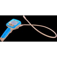
ET270 - Measuring equipment Klein Tools - Free user manual and instructions
Find the device manual for free ET270 Klein Tools in PDF.

User questions about ET270 Klein Tools
0 question about this device. Answer the ones you know or ask your own.
Ask a new question about this device
Download the instructions for your Measuring equipment in PDF format for free! Find your manual ET270 - Klein Tools and take your electronic device back in hand. On this page are published all the documents necessary for the use of your device. ET270 by Klein Tools.
USER MANUAL ET270 Klein Tools
Multi-Tester DMM with Receptacle Tester
• AUTO-RANGING WITH DATA HOLD
• AUDIBLE CONTINUITY
- BATTERY TEST
• PERFORMS STANDARD AND GFCI WIRING FAULT TESTS
• INDICATES A CIRCUIT'S BREAKER IN FIND MODE
600V \~ 40M Ω
text_image
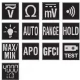
V Ω mV - AUTO RANGE HOLD MAX/ MIN APO GFCI TEST 4000 ECO
ESPAÑOL pg. 13
FRANÇAIS p. 25
KLEIN TOOLS®
text_image
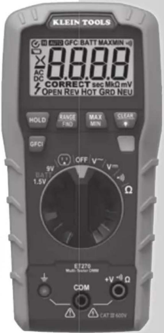
KLEIN TOOLS AUTO GFC BATT MAXMIN - 8.88.8 AC DC CORRECT sec MkΩ mV OPEN REV HOT GRD NEU HOLD RANGE FINI MAX MIN CLEAR GFC1 9V OFF V~ BATT 1.5V V mm Ω ET270 Multi-Tracker COMM COM +V ~ Ω CAT 600V
Intertek
5001748
CAT III
600V
GENERAL SPECIFICATIONS
Klein Tools' ET270 is an auto-ranging digital multi-tester that measures AC/DC voltage, resistance, continuity, and performs a battery test. It also tests wiring conditions in standard 120V and GFCI electrical receptacles and inspects North American GFCI devices.
- Environment: Indoor. DO NOT expose to moisture, rain, or snow.
- Operating Altitude: 6562 ft. (2000m)
- Relative Humidity: <80% non-condensing
- Operating Temp: 32°F to 104°F (0°C to 40°C)
• Storage Temp: 14°F to 140°F (-10°C to 60°C)
• Accuracy: Values stated at 65^ F to 83^ F ( 18^ C to 28^ C) - Temp Coeffi cient: 0.1 x (Quoted Accuracy) per °C above 28°C or below 18°C, corrections are required when ambient working temp is outside of Accuracy Temp range
- Dimensions: 6.41" × 3.13" × 1.84" (162.7 × 79.4 × 46.6 mm)
• Weight: 8.9 oz. (250 g)
• Calibration: Accurate for one year - Standards: Conforms to: UL STD 61010-1, 61010-2-033, 1436.
Certified to: CSA STD C22.2 # 61010-1, 61010-2-033, 160.
IEC EN 61010-1, 61010-2-033, 61326-1.
- Pollution degree: 2
- Accuracy: ± (% of reading + # of least significant digits)
- Drop Protection: 6.6 ft. (2 m)
- Safety Rating: CAT III 600V, Class 2, Double insulation
CAT III: Measurement category III is applicable to test and measuring circuits connected to the distribution part of the building's low-voltage MAINS installation. - Electromagnetic Environment: IEC EN 61326-1. This equipment meets requirements for use in basic and controlled electromagnetic environments like residential properties, business premises, and light-industrial locations.
Specifications subject to change.
ELECTRICAL SPECIFICATIONS
VOLTAGE (AUTO-RANGING)
| Function Range Resolution Accuracy | |||
| AC Voltage (V AC) | 400.0V 100mV ±(1.2% + 5 digits) | ||
| 600V 1V ±(1.2% + 3 digits) | |||
| DC Voltage (V DC) | 4000mV 1mV ±(1.0% + 5 digits) | ||
| 40.00V 10mV | ±(1.0% + 3 digits)400 | ||
| 600V 1V | |||
Input Impedance: 10MΩ
Frequency Range: 50 to 60Hz
Maximum Input: 600V AC RMS or 600V DC
RESISTANCE (AUTO-RANGING)
| Range Resolution Accuracy | ||
| 400.0Ω 0.1Ω | ±(1.0% + 5 digits) | |
| 4.000kΩ 1Ω | ||
| 40.00kΩ 10Ω | ||
| 400.0kΩ | 100Ω | |
| 4.000MΩ | 1kΩ | ±(1.2% + 5 digits) |
| 40.00MΩ | 10kΩ | ±(3.0% + 5 digits) |
Maximum Input: 600V DC or 600V AC RMS
BATTERY TEST
| Voltage | Resolution Accuracy | |
| 9V | 10mV | ±(1.0% + 5 digits) |
| 1.5V | 1mV | |
Test Current: 9V (11\~22.5mA), 1.5V (8\~18mA)
OUTLET* TEST
| Voltage | Resolution | Accuracy |
| 30V AC - 150 V AC | 1V | ±(2.0% + 2 digits) |
*NOTE: For North American, 120V, 50-60Hz, 3-wire receptacles only.
• Continuity Check: Audible signal <10Ω
- Sampling Frequency: 3 samples per second
• Overload: "OL" indicated on display, overload protection 600V RMS in all settings
- Polarity: "-" on display indicates negative polarity
• Display: 3-3/4 digit, 4000 Count LCD
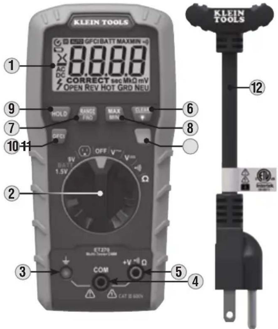
FEATURE DETAILS - TESTER
text_image
KLEIN TOOLS GFCI BATT MAXMIN 8.8.8 AC DC CORRECT sec MkΩ mV OPEN REV HOT GRD NEU HOLD RANGE FREQ MAX MIN CLOSE 6 7 8 10-11 OFF V- V= 9V BATT 1.5V Ω 2 3 4 5 CAT 10 BOXN KLEIN TOOLS 12- 4000 Count LCD Display
- Function Selector Switch
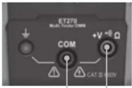
- Receptacle Jack
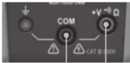
- "COM" Jack
- "+V·Ω" Jack
-
Clear/Backlight ON/OFF Button
-
"RANGE"/"FIND" Button
- "MAX/MIN" Button
- "HOLD" (Data Hold) Button
- "GFCI" Button
- Indicator LED
- Receptacle Test Cord
NOTE: There are no user-serviceable parts inside tester.
SYMBOLS ON TESTER
V Voltage (Volts)

AC Voltage

DC Voltage

Positive (DC Voltage)

Receptacle Test

Resistance (in Ohms)
BATT

Audible Continuity

Double Insulated Class II

Ground

Warning or Caution
To ensure safe operation and service of this tester, follow all warnings and instructions detailed in this manual.

Risk of Electrical Shock
Improper use of this tester can lead to risk of electrical shock. Follow all warnings and instructions detailed in this manual.

Read instructions
FEATURE DETAILS - LCD
text_image
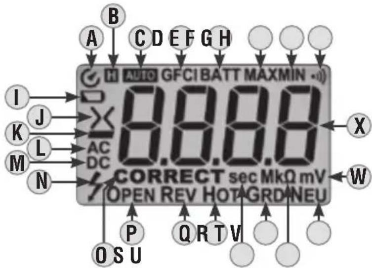
A B C D E F G H H AUTO GFCI BATT MAXMIN -0 I J X 8.8.8 K L AC M DC N CORRECT sec MkΩ mV OPEN REV HOTAGRDNEU P Q R T V O S UA Auto Power-Off Indicator
B Data Hold Indicator
C Automatic Ranging Indicator
D GFCI Indicator
E Battery Test Indicator
F Maximum Value Indicator
G Minimum Value Indicator
H Audible Continuity Indicator
I Low Battery Indicator
J Greater Than / Less Than Indicators
K Negative Polarity Indicator
L AC Voltage Indicator
M DC Voltage Indicator
N Hazardous Voltage Warning Indicator
0 Correct Wiring Indicator
P Open Circuit Indicator
Q Reversed Polarity Indicator
R Hot Conductor Indicator
S Seconds Indicator
T Ground Conductor Indicator
U Megaohms / Kiloohms Indicator
V Neutral Conductor Indicator
W Volts / Millivolts Indicator
X Measurement
WIRING CONDITIONS
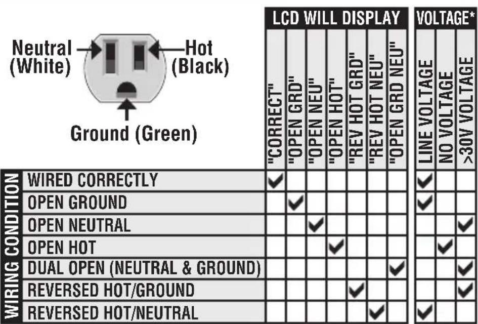
other
LCD WILL DISPLAY | Condition | WIREDCORRECTLY | OPENGROUND | OPENNEUTRAL | OPENHOT | DUALOPEN(NEUTRAL & GROUND) | REVERSED HOT/GROUND | REVERSED HOT/NEUTRAL | | :--- | :--- | :--- | :--- | :--- | :--- | :--- | :--- | | 'CORRECT' | ✓ | ✓ | ✓ | ✓ | ✓ | ✓ | ✓ | | 'OPEN GRD' | ✓ | ✓ | ✓ | ✓ | ✓ | ✓ | ✓ | | 'OPEN NEU' | ✓ | ✓ | ✓ | ✓ | ✓ | ✓ | ✓ | | 'OPEN HOT' | ✓ | ✓ | ✓ | ✓ | ✓ | ✓ | ✓ | | 'REV HOT GRD' | ✓ | ✓ | ✓ | ✓ | ✓ | ✓ | ✓ | | 'REV HOT NEU' | ✓ | ✓ | ✓ | ✓ | ✓ | ✓ | ✓ | | 'OPEN GRD NEU' | ✓ | ✓ | ✓ | ✓ | ✓ | ✓ | ✓ | VOLTAGE* LINE VOLTAGE NO VOLTAGE >30V VOLTAGE*Expected voltage reading on LCD based on the indicated wiring condition.
WARNINGS
To ensure safe operation and service of the tester, follow these instructions. Failure to observe these warnings can result in severe injury or death.
- Before each use:
- Verify meter operation by measuring a known voltage or current.
- Verify receptacle tester operation by testing on a known live and correctly wired electrical outlet.
- Never use the tester on a circuit with voltages that exceed the category based rating of this tester.
- Do not use the tester during electrical storms or in wet weather.
- Do not use the tester or test leads if they appear to be damaged.
- Probe assemblies to be used for MAINS measurements shall meet IEC/EN 61010-031 with a voltage RATING of CAT III 600V or better.
- Ensure tester leads or Receptacle Test Cord 12 are fully seated, and keep fingers away from the metal probe contacts when making measurements.
- Do not open the tester to replace batteries while the probes are connected.
- Use caution when working with voltages above 25V AC RMS or 60V DC. Such voltages pose a shock hazard.
- To avoid false readings when performing a receptacle test* that can lead to electrical shock:
- Replace batteries when a low battery indicator appears.
- All appliances or equipment on the circuit being tested should be disconnected.
- Turn off or move away from equipment which cause electromagnetic interference.
- Hold the body of the tester with a bare hand.
- Stand on or connect to earth ground.
- Perform test in an environment where air humidity is nominal (50% relative humidity).
-
Hold the tester still.
-
Do not attempt to measure resistance or continuity on a live circuit.
- Always adhere to local and national safety codes. Use personal protective equipment to prevent shock and arc blast injury where hazardous live conductors are exposed.
- The ET270 Receptacle Test Cord 12 is designed for use with North American 3-wire grounded 120V electrical outlets. DO NOT connect to higher voltage electrical supplies.
- The tester is intended for indoor use only.
- This receptacle tester operation only detects common wiring problems. ALWAYS consult a qualified electrician to resolve wiring problems. The device:
• Will not indicate quality of ground.
- Will not indicate two hot wires in a circuit.
- Will not detect a combination of multiple wiring faults.
- Will not indicate reversed ground and neutral.
- DO NOT attempt GFCI ground fault testing on an incorrectly wired circuit. Consult a qualified electrician to resolve wiring problems.
FUNCTION BUTTONS
ON/OFF
To Power ON the tester, rotate the Function Selector switch 2 from the OFF setting to any measurement setting. To Power OFF the tester, rotate the Function Selector switch 2 to the OFF setting. By default, the tester will automatically Power OFF after 15 minutes of inactivity. Reactivate tester by pressing any button. To deactivate the automatic Power OFF feature, power the tester ON with the "HOLD" button 9 depressed. When automatic Power OFF is deactivated, the symbol will not be visible in the display.
"HOLD" (DATA HOLD) BUTTON 9
Press the "HOLD" button to hold the measurement on the display. Press again to release the display and return to live measuring. Also used to deactivate auto Power OFF feature (see ON/OFF section above).
"RANGE" BUTTON ⑦
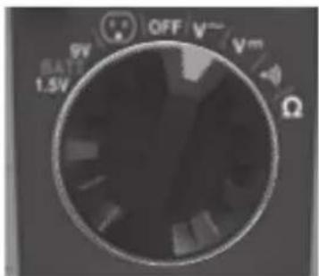
The tester defaults to auto-ranging measurement mode ^A the automatically determines the most appropriate measurement range for the testing that is being conducted. To manually force the tester to measure in a different range, use the "RANGE" button:
- Press to manually select measurement range (AUTO is deactivated on the LCD). Repeatedly press the "RANGE" button to cycle through the available ranges, stopping once the desired range is reached.
- To return to auto-ranging mode, press and hold for more than one second (AUTO is reactivated).
"MAX/MIN" BUTTON 8
When the "MAX/MIN" button is pressed, the tester keeps track of the minimum and maximum value of the measurement as the tester continues to take samples. The first press displays the Max value, the second press displays the Min value. To return to normal measuring mode, press and hold for more than one second.
"CLEAR"/BACKLIGHT BUTTON 6
- Press the "CLEAR"/Backlight button to exit hold mode; this will reset the LCD 1 to display "000 X, OPEN P, and HOT R when not connected to a circuit.
- Press and hold for more than one second to turn the LCD backlight on or off. The backlight automatically turns off after approximately 3 minutes.
"GFCI" BUTTON 10
To initiate an electrical fault press the "GFCI" button with the Receptacle Test Cord 12 inserted into the front jacks of the tester 3, 4, 5. The tester will create a 6mA to 9mA ground fault to trip the GFCI device. See GFCI TEST section in OPERATING INSTRUCTIONS for more information.
OPERATING INSTRUCTIONS
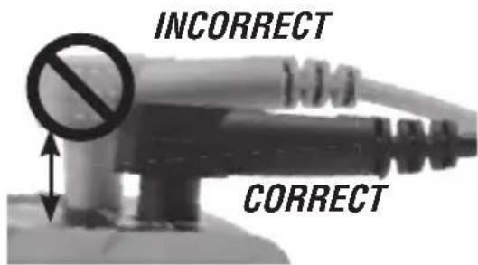
CONNECTING TEST LEADS
Do not test if leads are improperly seated. Results could cause intermittent display readings. To ensure proper connection, firmly press leads into the input jack completely.
text_image
INCORRECT CORRECTTESTING IN CAT III / CAT IV MEASUREMENT LOCATIONS
Ensure the test lead shield is pressed firmly in place. Failure to use the CAT III / CAT IV shield increases arc-flash risk.
text_image
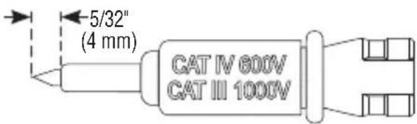
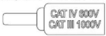
5/32" (4 mm) CAT IV 600V CAT III 1000VTESTING IN CAT II MEASUREMENT LOCATIONS
CAT III / CAT IV shields may be removed for CAT II locations. This will allow testing on recessed conductors such as standard wall receptacles. Take care not to lose the shields.
text_image
CAT IV 800V CAT III 1000V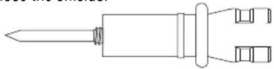
natural_image
Line drawing of a screwdriver with two ports and a central shaft (no text or symbols)AC/DC VOLTAGE (LESS THAN 600V)
-
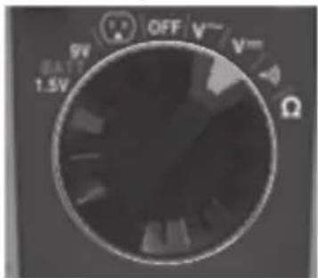
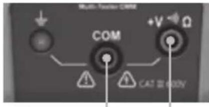
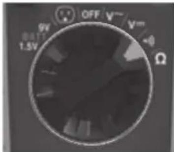
Insert RED test lead into +V•Ω jack ⑤, and BLACK test lead into COM jack ④, and rotate Function Selector Switch ② to the V-or V-setting.
-
Apply test leads to the circuit to measure voltage. The tester will auto-range to display the measurement in the most appropriate range.
NOTE: If the Negative Polarity Indicator K appears on the LCD, the test leads are being applied to the circuit in reverse polarity. Swap the position of the leads to correct this.
NOTE: When in a voltage setting and the test leads are open, readings of order mV may appear on the display. This is noise and is normal. By touching the test leads together to close the circuit the tester will measure zero volts.
NOTE: The Hazardous Voltage Warning Indicator N will appear for voltages above 25V.
text_image
ET270 Multi-Tensor 2M68 COM +V Ω CAT 32 600VRed leadBlac
text_image
9V BATT 1.5V OFF V~ V~ Ω-OR-
text_image
9V BATT 1.5V OFF Vmm ΩOPERATING INSTRUCTIONS
RESISTANCE MEASUREMENTS
-
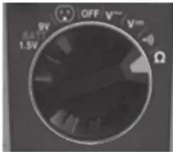
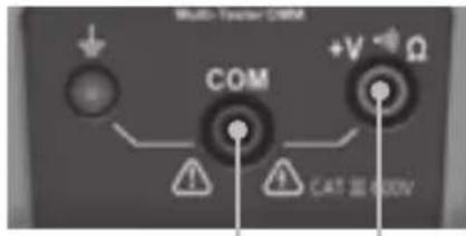
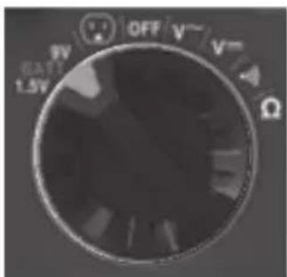
Insert RED test lead into V • Ω jack ⑤, and BLACK test lead into COM jack ④, and rotate Function Selector Switch ② to the Resistance Ω setting.
-
Remove power from circuit.
- Measure resistance by connecting test leads to circuit. The tester will auto-range to display the measurement in the most appropriate range.
NOTE: When in a Resistance setting and the test leads are open (not connected across a resistor), or when a failed resistor is under test, the LCD ① will indicate DL This is normal.
text_image
Multi-Factor COM COM +V - Φ Ω CAT 32 600VRed leadBlac
text_image
OFF V 1.5V RATI ΩDO NOT attempt to measure resistance on a live circuit.
CONTINUITY
- Insert RED test lead into +V•Ω jack 5, and BLACK test lead into COM jack 4, and rotate Function Selector Switch 2 to the Continuity • setting.
- Remove power from circuit.
- Test for continuity by connecting conductor or circuit with test leads. If resistance is measured less than 10Ω, an audible signal will sound and display will show a resistance value indicating continuity. If circuit is open, display will show "OL".
⚠ DO NOT attempt to measure continuity on a live circuit.
text_image
Multi-Tweater COM COM +V +Ω CAT Ⅲ 600VRed leadBlac
text_image
9V 1.5V OFF V~ V~ ΩBATTERY TEST
- Insert RED test lead into +V•Ω jack ⑤ and BLACK test lead into COM jack ④, and rotate Function Selector Switch ② to the 1.5V or 9V BATT setting.
- Connect BLACK lead to negative, and RED lead to positive terminal of battery.
- The voltage measured will display on the LCD X. Batteries in good condition should be
within approx. 10% of rated voltage.
text_image
COM +V ~Ω CAT 3500VRed leadBlac
-OR-
text_image
9V EAT1 1.5V OFF V~ V~ ΩOPERATING INSTRUCTIONS
RECEPTACLE TEST
ET270 Receptacle test is designed for use with North American 3-wire, grounded 120V electrical outlets. DO NOT connect to higher voltage electrical supplies.
⚠️ Prior to use, always verify tester operation by testing on a known live and correctly wired electrical circuit.
-
With the Receptacle Test Cord 12 inserted into the front jacks of the tester 3, 4, 5, rotate Function Selector Switch 2 to the Receptacle Test setting. When the tester is powered on, and not connected to a circuit the LCD 1 will display "X", OPEN P, and HOT R. On powerup, the display will flash "three times, indicating that the Receptacle Test Cord should be used rather than test leads.
-
With the tester powered ON and inserted into the receptacle to be tested, the Indicator LED 11 will illuminate either red or green:
- If the Indicator LED 11 illuminates red, the circuit is not wired correctly and/or the voltage is not between 85V AC and 135V AC. Note the voltage X and wiring fault(s) O, P, Q, R, T, V indicated (see table in WIRING CONDITIONS section). When the receptacle is de-energized or the tester is unplugged, the tester holds the information on the LCD and the Data Hold Indicator B will illuminate. During this time, the Indicator LED 11 will blink. If no voltage is detected, the LCD will reset after approximately 10 seconds. If the tester is plugged into another circuit, the LCD will update to show the voltage and wiring condition of that circuit.
⚠️ If the tester indicates that the circuit is not wired correctly, consult a qualified electrician.
- If the Indicator LED 11 illuminates green, the circuit is wired correctly, and the voltage is between 85V AC and 135V AC.
NOTE: The Hazardous Voltage Indicator Ⓝ will appear if the detected voltage is above 25V AC.

text_image
ET270 Multi-Transformer COM +V Ω CAT 11 600V KLEIN TOOLS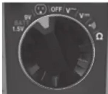
text_image
9V OFF V~ V~ BATT 1.5V ΩOPERATING INSTRUCTIONS
GFCI TEST
NOTE: Refer to the GFCI device's user manual for information on installation and operation prior to testing. Check for correct wiring of GFCI receptacle and all receptacles on the circuit.
-
Operate the test button on the GFCI in the circuit:
-
If the GFCI does not trip, do not use the circuit and consult a qualified electrician.
-
If the GFCI does trip, reset the GFCI.
-
Insert the Receptacle Test Cord 12 into the front jacks of the tester 3, 4, 5, then plug in the NEMA 5-15P end of the Receptacle Test Cord 12 into the GFCI receptacle to be tested.
-
To initiate an electrical fault, press the "GFCI" button 10. The tester will create a 6mA to 9mA ground fault to trip the GFCI device.
-
If the GFCI trips, the device is wired properly and circuit will de-energize. The tester will stop indicating voltage.
- If the GFCI doesn't trip, it suggests either improper wiring or a faulty GFCI. The tester will continue to indicate voltage. Contact a qualified electrician to resolve wiring problems.
FIND FUNCTION
The FIND function is used to indicate which breaker corresponds to a given receptacle:
- While in Receptacle Test mode and with the Receptacle Test Cord ⑫ inserted into the receptacle to be located, press the "RANGE/FIND" Button ⑦. NOTE: the FIND function cannot be used if the wiring condition of the circuit is "Open Hot".
- The tester will emit a warble tone while the receptacle is energized. Begin turning off breakers at the panel one by one.
- When the breaker for that receptacle is turned off, the warble tone will stop, and the Indicator LED 11 will flash ten times.
- After the ten flashes, the tester will automatically exit the FIND function. To exit the FIND function manually, press the "RANGE/FIND" Button ⑦.
BATTERY REPLACEMENT
When the Low Battery Indicator ☐ is displayed on the LCD, the batteries must be replaced.
- Loosen captive screw and remove battery door.
- Replace two AAA batteries (note proper polarity).
- Replace battery door and fasten securely with screw.
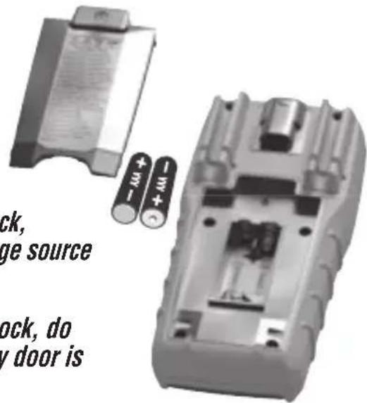
text_image
ck, ge source ock, do y door isTo avoid risk of electric shock, disconnect leads from any voltage source before removing battery door.
To avoid risk of electric shock, do not operate tester while battery door is removed.
CLEANING
Be sure tester is turned off and wipe with a clean, dry lint-free cloth. Do not use abrasive cleaners or solvents.
STORAGE
Remove the batteries when tester is not in use for a prolonged period of time. Do not expose to high temperatures or humidity. After a period of storage in extreme conditions exceeding the limits mentioned in the General Specifications section, allow the tester to return to normal operating conditions be fore using.
FCC & IC COMPLIANCE
See this product's page at www.kleintools.com
for FCC compliance information.
Canada ICES-003 (B) / NMB-003 (B)
WARRANTY
Do not place equipment and its accessories in the trash. Items must be properly disposed of in accordance with local regulations. Please see www.epa.gov/recycle for additional information.
CUSTOMER SERVICE
KLEIN TOOLS, INC.
450 Bond Street Lincolnshire, IL 60069 1-800-553-4676
customerservice@kleintools.com www.kleintools.com
text_image
A B C D E F G H H AUTO GFCI BATT MAXMIN -10 I J X 8.88.8 K L AC M DC N CORRECT sec MkΩ mV OPEN REV HOTAGRDNEU P Q R T V O S UBOTÓN "HOLD" (RETENER) ⑨
natural_image
Line drawing of a screwdriver with two ports and a handle (no text or symbols)VOLTAJE CA/CD (MENOS DE 600 V)
+ Tension c.c. positive