Capatek 66 FV - Welding machine GYS - Free user manual and instructions
Find the device manual for free Capatek 66 FV GYS in PDF.

User questions about Capatek 66 FV GYS
0 question about this device. Answer the ones you know or ask your own.
Ask a new question about this device
Download the instructions for your Welding machine in PDF format for free! Find your manual Capatek 66 FV - GYS and take your electronic device back in hand. On this page are published all the documents necessary for the use of your device. Capatek 66 FV by GYS.
USER MANUAL Capatek 66 FV GYS
natural_image
Technical line drawing of a portable electronic device with control panel and buttons (no text or symbols)CAPATEK 66 FV
FR 02-13 / 14-20
EN 21-31 / 32-38
DE 39-50 / 51-57
NL 58-68 / 69-75
IT 76-86 / 87-93
RU 94-104 / 105-112
I. GÉNÉRATEUR FIG.1
text_image
Technical diagram of an electronic device with labeled components, showing front and side views with numbered parts.text_image
1 2 3 888 ← → ← ← 678text_image
Labeled diagram of a welding torch with numbered parts for identification and assembly reference.V. FONCTIONS DE LA LED INTÉGRÉES AU PISTOLET
text_image
Technical diagram of a mechanical component with labeled parts 1 and 2text_image
Technical diagram of a mechanical component with labeled parts and directional arrows indicating motion or force directions.natural_image
Technical diagram of a circular mechanical component with numbered parts and red curved arrows indicating rotation or motion (no text or symbols)natural_image
Technical line drawing of a mechanical component with no visible text or symbolsnatural_image
Close-up of a cylindrical mechanical component with threaded end and flange (no visible text or symbols)natural_image
Mechanical component diagram showing a circular housing with internal components and red curved arrows indicating rotational motion (no text or symbols)
natural_image
Technical line drawing of a circular mechanical component with multiple ports and mounting holes (no text or symbols)natural_image
Technical line drawing of a mechanical component with no visible text or symbolsnatural_image
Technical line drawing of a mechanical device with no visible text or symbolstext_image
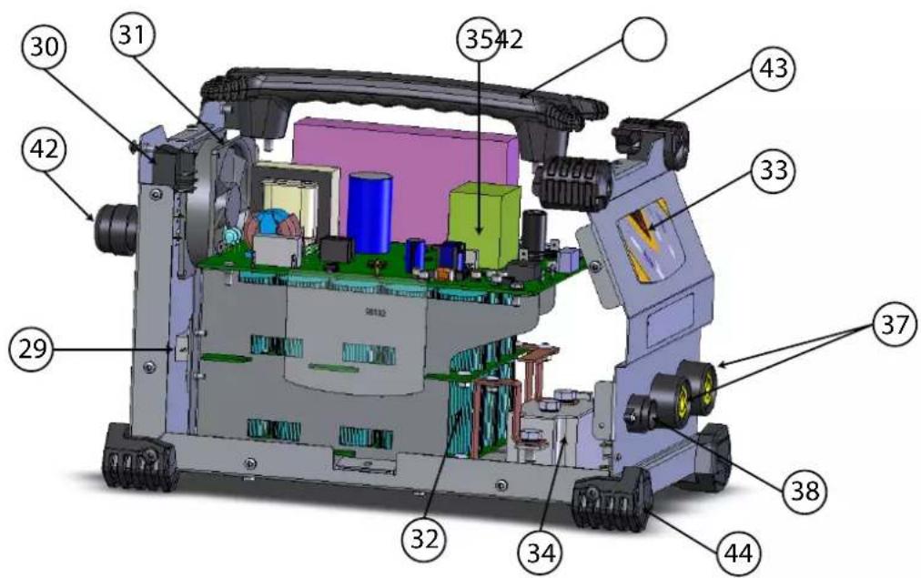
Technical diagram of a mechanical device with numbered components for identification| N° Désignation Qté Contact Retrait | ||||
| 29 | Résistance 50W 68 ohms / 50W 68 ohms resistance / Resistenza 50W 68 ohms / Weerstand 50W 68 ohms | 1 | 98630 | |
| 30 | Interrupteur orange lumineux (22/30) O-I / Luminous orange switch (22/30) O-I / Interrtore arancione luminoso (22/30) O-I / Verlichte oranje schakelaar (22/30) O-I | 1 52460 | ||
| 31 | Ventilateur / Fan / Ventilator / Ventilador / Вентилятор / Ventilatore / Ventilator 92x92x25 24 Vdc | 1 | 51048 | |
| 32 | PCB condensateur Aluspot / PCB capacitor Aluspot / Condensatore PCB Aluspot / PCB condensator Aluspot | 1 | 97156C | |
| 33 | Clavier / Keyboard / Bedienfeld / Панель управления / Tastiera / Bedieningspaneel | 1 | 51928 | |
| 34 | Module Thyristor - Diode 400A / Thyristor module - 400A diode / Modulo Tiristore - Diodo 400A / Module Thyristor - Diode 400A | 1 52159 | ||
| 35 | PCB Gestion / Managing PCB / Gestione PCB / PCB Besturen 1 E0178C | |||
| 36 | Cordon secteur 3x2.50 mm ^2 - H07RNF - 2.20m - Prise EU 1 21462 | |||
| 37 | Embase Texas H21 Femelle - CX0031 - Sect. max 70 mm ^2 - Version HF | 1 51468 | ||
| 38 | faisceau 5 fils sur 7 | 1 71873 | ||
| 39 | Solenoide | 1 | F0979 | |
| 40 | Faisceau pistolet | 1 | F0945ST | F1024SF |
| 41 | Câble de masse Y | 1 | F0948 | F1021 |
| 42 | Presse étoupe | 1 71148 | ||
| 43 | Patin angle | 4 56163 | ||
| 44 | Pied angle | 4 56120 | ||
ICÔNES / SYMBOLS / ZEICHENERKLÄRUNG / ICONOS / СИМВОЛЫ / PITTOGRAMMI / PICTOGRAMMEN
 | - Attention! Lire le manuel d'instruction avant utilisation.- Caution! Read the user manual.- Achtung! Lesen Sie die Betriebsanleitung.- iCuidado! Lea el manual de instrucciones antes de su uso.- Внимание! Прочтите инструкцию перед использованием.- Attenzione! Leggere il manuale utente.- Let op! Lees aandachtig de handleiding. |
| A | Ampères - Amps - Ampere - Amperios - Ампер - Amps - Ampere |
| V | Volt - Volt - Volt - Voltio - Вольт - Volt - Volt |
| Hz | Hertz - Hertz - Hertz - Hercio - Герц - Hertz - Hertz |
 | - Convient au soudage dans un environnement avec risque accru de choc électrique. La source de courant elle-même ne doit toutefois pas être placée dans de tels locaux. - Adapted for welding in environments with increased risk of electrical shock. However, the welding machine should not be placed in such places. - Geeignet für Schweibarbeiten im Bereich mit erhöhten elektrischen Risiken. Trotzdem sollte die Schweibquelle nicht unbedingt in solchen Bereichen betrieben werden. - Adaptado a la soldadura en un entorno que comprende riesgos de choque eléctrico. La fuente de corriente ella misma no debe estar situada dentro de tal locales. - Подходит для сварки в среде с повышенной опасностью удара электрическим током. Тем не менее не следует ставить источник тока в такие помещения. - Geschikt voor het lassen in een ruimte met verhoogd risico op elektrische schokken. De voedingsbron zelf moet echter niet in dergelijke ruimte worden geplaatst. - È consigliato per la saldatura in un ambiente con grandi rischi di scosse eletriche. La fonte di corrente non deve essere localizzata in tale posto. |
| IP21 | - Protégé contre l'accès aux parties dangereuses avec un dolgt, et contre les chutes verticales de gouttes d'eau- Protected against rain and against fingers access to dangerous parts- Geschützt gegen Berührung mit gefährlichen Teilen und gegen senkrechten Wassertropfenfall- Protegido contra el acceso a partes peligrosas con el dedo y contra las caidas verticales de gotas de agua- Защищен от доступа пальцев в опасные части, а также от попадения вертикальных капель воды- Beveiligd tegen de toegang tot gevaarlijke delen met een vinger, en tegen verticala vallende waterdruppels- Protette contro pioggia e contro l'accesso delle dita in parti pericolose+ |
| U_1N | Tension d'alimentation assignée - Rated power supply voltage - Nennspannung - Tensión de alimentación asignada - Номинальное напряжение питания - Nominate voedingsspanning - Tensione di alimentazione nominale |
| [37V08] | Puissance permanente (au facteur de marche de 100%) - Permanent power (at a 100% duty cycle) - Dauerleistung (@ 100%) - Potencia permanente (al ciclo de trabajo de 100%) - Постоянная мощность (при ПВ 100%) - Permanent vermogen (bij een inschakelduur van 100%) - Potenza permanente (al fattore di marcia de 100%) |
| [СИТО] | Courant maximal de court-circuit secondaire - Maximal current of a secondary short circuit - Maximaler sekundärer Kurzschlussstrom - Corriente máxima de cortocircuito secundario - Максимальный ток короткого замыкания на вторичке - Secondaire maximale kortsluitingsstroomsterkte - Corrente massima di corto-circuito secondario |
| [84A4] | Courant permanent au secondaire - Continuous secondary current - Dauerstrom an der Sekundärseite - Corriente continua secundaria - Непрерывный вторичный ток - Continue secundaire stroom - Corrente secondaria continua |
| m | Masse de la machine - Machine weight - Masse der Maschine - Peso de la máquina - Bec машины - Gewicht machine - Peso della macchina |
| Courant de soudage continu - Direct welding current - Gleichschweißstrom - Corriente continua de soldadura - Continue lasstroom - Corrente di saldatura continua | |
 | - Matériel conforme aux Directives européennes. La déclaration UE de conformité est disponible sur notre site (voir à la page de couverture).- Device complies with europeans directives, The EU declaration of conformity is available on our website (see cover page).- Gerät entspricht europäischen Richtlinien. Die Konformitätserklärung finden Sie auf unsere Webseite.- Aparato conforme a las directivas europeas. La declaración de conformidad UE está disponible en nuestra página web (dirección en la portada).- Устройство соответствует директивам Евросоюза. Декларация о соответствии доступна для просмотра на нашем сайте (ссылка на обложке).- Apparaat in overeenstemming met de Europese richtlijnen. De verklaring van overeenstemming is te downloaden op onze website (adres vermeld op de omslag).- Materiale in conformità alle Direttive europee. La dichiarazione di conformità è disponibile sul nostro sito (vedere sulla copertura). |
 | - Marque de conformité EAC (Communauté économique Eurasienne).- Conformity mark EAC (Eurasian Economic Commission).- EAC-Konformitätszeichen (Eurasische Wirtschaftsgemeinschaft).- Marca de conformidad EAC (Comunidad económica euroasiática).- Маркировка соответствия EAC (Евразийское экономическое сообщество).- Marchio conformità EAC (Commissione economica eurasiatica).- EAC (Euraziatische Economische Gemeenschap) merkteken van overeenstemming |
 | - Matériel conforme aux exigences britanniques. La déclaration de conformité britannique est disponible sur notre site (voir à la page de couverture).- Equipment in compliance with British requirements. The British Declaration of Conformity is available on our website (see home page).- Das Gerät entspricht den britischen Richtlinien und Normen. Die Konformitätserklärung für Grossbritannien ist auf unserer Internetseite verfügbar (siehe Titelseite).- Equipo conforme a los requisitos británicos. La Declaración de Conformidad Británica está disponible en nuestra página web (véase la portada).- Материал соответствует требованиям Великобритании. Заявление о соответствии для Великобритании доступно на нашем веб-сайте (см. главную страницу).- Materiaal conform aan de Britse eisen. De Britse verklaring van overeenkomt is beschikbaar op onze website (zie omslagpagina).- Materiale conforme alla esigenze britanniche. La dichiarazione di conformità britannica è disponibile sul nostro sito (vedere pagina di copertura). |
 | - CMIM : Certification Marocaine- CMIM : Moroccan Certification- CMIM : Marokkanische Zertifizierung- CMIM : Certificación Marroqui- CMIM : - CMIM : Марокканская сертификация- CMIM : Marokkaanse certificering- CMIM : Certificazione Marocchina |
| ISO 669:2016 | La source de courant de soudage est conforme aux normes IEC62135-1 et EN ISO 669 - The welding current source complies with IEC62135-1 and EN ISO 669 standards- Die Schweißstromquelle entspricht den Normen IEC62135-1 und EN ISO 669 - El generador de soldadura cumple las normas IEC62135-1 y EN ISO 669 - Источник сварочного тока соответствует стандартам IEC62135-1 и EN ISO 669 - De lasgenerator voldoet aan de IEC62135-1 en EN ISO 669 normen - La sorgente di corrente di saldatura è conforme alle norme IEC62135-1 e EN ISO 669 |
  | - L'arc électrique produit des rayons dangereux pour les yeux et la peau (protégez-vous !).- The electric arc produces dangerous rays for eyes and skin (protect yourself !).- Der elektrische Lichtbogen verursacht Strahlungen auf Augen und Haut (Schützen Sie sich !).- El arco eléctrico produce radiaciones peligrosas para los ojos y la piel. Protéjase.- Электрическая дуга дает излучение опасное для глаз и кожи (носите защитную одежду!).- L'arco elettrico produce raggi pericolosi per gli occhi e la pelle (proteggers!!).- Booglassen kan gevaarlijk zijn en ernstige en zelfs dodelijke verwondingen veroorzaken.- Produit faisant l'objet d'une collecte sélective - Ne pas jeter dans une poubelle domestique.- Separate collection required, Do not throw in a domestic dustbin.- Für die Entsorgung Ihres Gerätes gelten besondere Bestimmungen (Sondermüll). Es darf nicht mit dem Hausmüll entsorgt werden.- Este producto es objeto de una colecta selectiva - Ne lo tire a la basura doméstica.- Этот аппарат подлежит утилизации - Не выбрасывайте ero в домашний мусоропровод.- E' richiesta una raccolta differenziata, non gettare in un bidone della spazzatura domestica.- Afzonderlijke inzameling vereist volgens de Europese richtlijn 2012/19/UE. Gooi het apparaat niet bij het huishoudelijk afval ! |
 | - Produit recyclable qui relève d'une consigne de tri.- This product should be recycled appropriately.- Recyclingprodukt, das gesondert entsorgt werden muss.- Producto reciclable que requiere una separación determinada.- Этот аппарат подлежит утилизации.- Product recyclebaar, niet bij het huishoudelijk afval gooien.- Prodotto riciclabile soggetto a raccolta differenziata. |
| [IMAGE] | - Information sur la température (protection thermique)- Temperature information (thermal protection)- Information zur Temperatur (Thermoschutz)- Información sobre la temperatura (protección térmica)- Информация по температуре (термозащита)- Informazioni temperatura (protezione termica)- Informatie over de temperatuur (thermische beveiliging) |
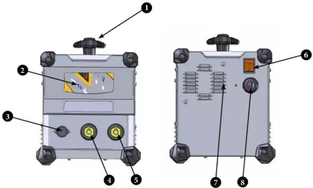
I. POWER SOURCE FIG.1

text_image
Technical diagram of an electronic device with labeled components, showing front and side views with numbered parts.| 1 Cable storage handle |
| 2 Keypad |
| 3 Connector for gun cabling control plug |
| 4 Positive dinse socket for gun cable |
| 5 Negative dinse socket for gun cable |
| 6 ON/OFF switch |
| 7 Cooling vents |
| 8 Power Supply Cable |
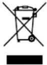
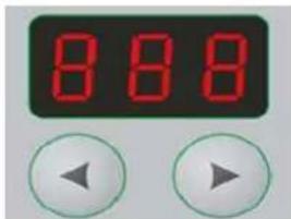
II. USER INTERFACE FIG.10
text_image
1 2 3 888 ← → ← ← 678| 1 Voltage display in volts (default display) |
| 2 Trigger press indicator |
| 3 Contact between stud and workpiece indicator. |
| 4 Decrease the set voltage value / Navigate menus |
| 5 Increase the set voltage value/ Navigate menus |
| 6 Go back or cancel in menus |
| 7 Thermal trip indicator |
| 8 Access the menu or Confirm |
FUNCTIONS ACCESSIBLE VIA THE MENU FIG.11
| Incremental counting mode for stud counter with threshold adjustment | Mod/ ▼/threshold adjustment |
| Decremental counting mode of the stud counter with threshold adjustment | Mod/ ▼/threshold adjustment |
| desactivation of the stud counter Mod/Off | |
| View current stud counter value Stu ou Appui sur gâchette | |
| resetting the stud counter to zero Stu/Rst/yes | |
| Consultation and adjustment of stud counters | Stu/ ▼/□ ▼ ▼ ▼ |
| Gun LED activation Led/On | |
| Gun LED deactivation Led/Off | |
| Lock settings Loc/ON | |
| Unlock settings Loc/Off | |
| Standby Sby/ON | |
| Exit standby Any key on the keypad | |
| Increasing or decreasing the counter Welding a stud | |
| Cancelling a step increment or decrement of the counter | Pull trigger + 📁️ ⚫️ ⚫️ |
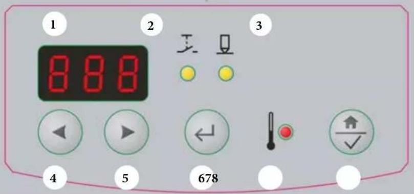
III. GUN FIG.12
text_image
Technical diagram of a welding torch with numbered parts for identification and assembly reference.| 1 Tripod ring with quarter-turn locking mechanism | |
| 2 Tripod rod with tightening flats | |
| 3 | Retaining screw for retraction height adjustment cover (not present on contact gun version) |
| 4 Slider for adjusting retraction height from 1 to 5 mm | |
| 5 Cover for height adjustment knob (not present on contact gun version) | |
| 6 LED light | |
| 7 Screw to retain the force adjustment knob cover | |
| 8 Force adjustment knob cover | |
| 9 Stud holder | |
| 10 Force adjustment slider | |
| 11 Welding trigger | |
| 12 Gun control cable connector | |
| 13 Positive dinse | |
IV. ACCESSORIES
- Tripod ring with quarter-turn locking mechanism (Fig 12.1)
| Place the tripod in this position, then make a quarter turn to the right | Tripod in correct position |
 |  |
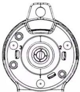
By default, the tripod pins are positioned in inserts 1, 2 and 3.
In order to perform welds in difficult positions or on thin sheet material, the pins can be positioned differently if required. Note: the pins do not act as earth contacts
- Stud holder
A stud holder box (080935) is available as an optional accessory:
| M3 (081215) |
| M4 (049000) |
| M5 (048157) |
| M6 (048164) |
| M8 (064058) |
V. LED FUNCTIONS INCORPORATED INTO THE GUN
• Welding area illumination
- Switches off when the machine is being charged, and lights up continuously when the machine is ready.
- Flashes rapidly when an error has occurred
- Flashes slowly when the stud count threshold is reached.
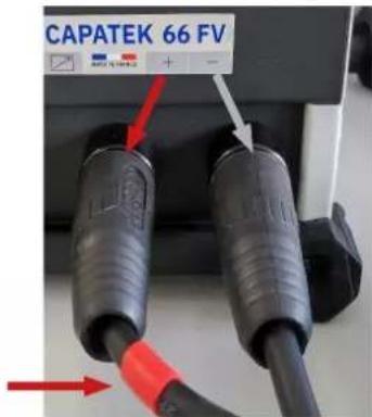
VI. POLARITY
The polarity of the gun has an impact on the quality of the weld.
R+; The dinse plug, with the red marking on the gun cable, is attached to the positive socket.
N+; The dinse plug from the ground clamps is attached to the positive socket.
Below is the polarity selection suggested by GYS depending on the material:
| COPPER-PLATED STEEL | Stainless steel ALUMINIUM BRASS | |
| R+ N+ R+ N+ |
text_image
CAPATEK 66 FVWARNINGS - SAFETY INSTRUCTIONS
GENERAL INSTRUCTIONS

These instructions must be read and fully understood before use.
Do not carry out any alterations or maintenance work that is not directly specified in this manual.
The manufacturer is not liable for any injury or damage caused due to non-compliance with the instructions featured in this manual. In the event of a problem or uncertainties, consult a qualified person in order to correctly commission the equipment.
The instructions concern the equipment in the condition it was delivered. It is the responsibility of the user to analyse the risks taken when not following the instructions published by GYS.
ENVIRONMENT
This equipment should only be used for welding operations performed within the limits indicated on the information panel and/or in this manual. These safety guidelines must be observed. In the event of improper or dangerous use, the manufacturer cannot be held responsible.
The machine must be used in an environment free of dust, acid, flammable gas, or other corrosive substances. This also applies to storage on the unit. Operate the machine in an open, or well-ventilated area.
Temperature range:
Use between -10 and +40°C (+14 and +104°F).
Store between -20 and +55°C (-4 and 131°F).
Air humidity:
Lower than or equal to 50% at 40°C (104°F).
Lower than or equal to 90% at 20°C (68°F).
Altitude: Up to 1,000m above sea level (3280 feet).
PROTECTING YOURSELF AND OTHERS
Capacitive discharge equipment can be dangerous and cause serious injury or death. The machine is intended to be operated by qualified personnel who have received appropriate training in the use of the machine (eg: panel beater training).
Welding exposes people to dangerous heat, sparks, electromagnetic fields (beware if you have a pacemaker), risk of electrocution, noise, and gas emissions.
To protect yourself and others, please comply with the following safety instructions:

To protect yourself from burns and radiation, wear clothes without cuffs/lapels, that are insulating, dry, fireproof and in good condition, and that cover the whole body.

Wear protective gloves which provide electrical and thermal insulation.

Use welding protection and/or a welding helmet with a sufficient level of protection (depending on the specific use). Protect your eyes during cleaning procedures. Contact lenses are specifically forbidden. It may sometimes be necessary to mark off areas with fireproof curtains in order to protect others from splashes, sparks, and arc-eye. Ask people around the working area to look away from at the arc and molten metal, and to wear protective clothing.

Wear noise protection headphones if the welding process becomes louder than the permissible limit (this is also applicable to anyone else in the welding area).
Newly welded parts are hot and can cause burns when handled.
It is important to secure the working area before leaving it, in order to protect people and property.
WELDING FUMES AND GAS

Fumes, gases and dusts emitted by welding are harmful to health. It is mandatory to ensure adequate ventilation, and an additional air supply may be required. An air-fed mask could be a solution in situations where there is inadequate ventilation.
Check the extraction system's performance against the relevant safety standards.
Care should be taken when welding in confined spaces, and supervision from a safe distance is essential. In addition, welding certain materials containing lead, cadmium, zinc, mercury, or even beryllium, can be particularly harmful.
Remove any grease from workpieces before welding. Welding should not be carried out near grease or paint.
RISK OF FIRES AND EXPLOSIONS

Fully protect the welding area, and ensure that flammable materials are kept at least 11 metres away. Fire fighting equipment should be kept close to wherever the welding activities are being undertaken.
Beware of hot materials and sparks being projected, even through cracks, as they can potentially be the source of a fire or explosion. Keep people, flammable objects and pressurised containers at a safe distance. Welding in closed containers or tubes should be avoided, and if they are open, they should be emptied of any flammable or explosive materials (oil, fuel, residual gas, etc.).
Grinding work must not be directed towards the source of the welding current or towards any flammable materials.
ELECTRICAL SAFETY

The electrical network used must be earthed. A direct or indirect electric shock can cause a serious injury, or even death.
Do not touch any live part, either inside or outside of the machine, when it is plugged in (cables, electrodes, arms, gun, etc.), as these are all linked to the welding circuit.
Before opening the welding power source, disconnect it from the mains supply and wait 2 minutes. This will ensure that all the capacitors are discharged.
Ensure that all cables, electrodes, or arms, are changed by qualified and authorised personnel if they are damaged. Measure the cable cross-section according to the intended application. Always use dry and in-tact clothing to insulate yourself from the welding circuit. Wear insulated shoes in all working environments.
EMC CLASSIFICATION

This Class A device is not intended for use in a residential environment where power is provided by the public low-voltage local supply network. There may be potential difficulties in maintaining electromagnetic compatibility at these sites, due to both conducted, and radiated radio frequency interference.
EN 61000-3-12 This equipment complies with the IEC 61000-3-12 standard.
EN 61000-3-11 This equipment complies with IEC 61000-3-11.
ELECTROMAGNETIC INTERFERENCES
An electric current passing through any conductor produces localised electric and magnetic fields (EMF). The welding current produces an electromagnetic field around the welding circuit and the welding equipment.
Electromagnetic fields (EMFs) can interfere with some medical devices, pacemakers for example. Protective measures must be taken for people with medical implants. For example, restricted access for spectators, or an individual risk assessment for welders.
All welders should use the following procedures to minimise exposure to electromagnetic fields from the welding circuit:
- position the welding cables together with – secure them with a clip, if possible;
- position your body and head as far as possible from the welding circuit;
- never wrap welding cables around your body;
- do not position yourself in between the welding cables. Both welding cables should be placed on the same side of the body;
- Connect the earth cable to the workpiece, as close as possible to the welding area;
- do not work directly next to the welding power source, Do not sit on, or lean against it;
- do not move the welding power source or wire feeder while it is in use.

Pacemaker users should consult a doctor before using this equipment.
Exposure to electromagnetic fields during welding may have other health effects that are not yet known.
RECOMMENDATIONS FOR ASSESSING THE WELDING AREA AND EQUIPMENT
General Information
The user is responsible for installing and using the capacitive discharge equipment in accordance with the manufacturer's instructions. If electromagnetic interference is detected, it is the responsibility of the user of the capacitive discharge machine to rectify the situation using technical assistance from the manufacturer. In some cases, this corrective action may be as simple as earthing the welding circuit. In other cases, it may be necessary to electromagnetically shield the welding power source, and the workpiece as a whole, by installing input filters. In all cases, electromagnetic interference should be reduced until it is no longer a concern.
Assessing the welding area
Before installing capacitive discharge equipment, the user should assess the potential electromagnetic problems in the surrounding area. The following should be taken into account:
a) the presence above, below, and next to the capacitive discharge equipment, of power cables, command cables, and other signal or telecommunication wiring;
b) radio and television receivers and transmitters;
c) computers and other control equipment;
d) critical safety equipment, for example, industrial equipment protection;
e) the well-being of nearby persons, for example, use of pacemakers or hearing aids;
f) the equipment used for calibrating or measurment;
g) the sensitivity of other equipment in the surrounding area.
The user must ensure that other equipment installed in the vicinity is compatible. This may require further protective measures; h) the time of day when welding or other tasks are to be carried out.
The size of the surrounding area to be taken into account will depend on the building's structure and the other activities taking place there. The surrounding area may extend beyond the boundaries of the facility.
Assessment of the welding equipment
In addition to assessing the area, the assessment of capacitive discharge equipment installations can be used to identify and resolve cases of interference. The assessment of emissions should include in-situ measurements, as specified in Article 10 of CISPR 11:2009. In-situ measurements can also be used to verify the effectiveness of any mitigation measures.
GUIDELINES ON HOW TO REDUCE ELECTROMAGNETIC EMISSIONS
a. Power supply network: The capacitive discharge unit should be connected to the power supply network in accordance with the manufacturer's recommendations. If interference occurs, it may be necessary to take additional precautionary measures such as filtering the mains power supply. With capacitive discharge equipment that is to be permanently installed, consideration should be given to shielding the power cable in metal ducting or equivalent. The power cable should be protected along its entire length. The shield should be connected to the welding power source to ensure that there is good electrical contact between the conduit and the welding power source enclosure.
b. Maintenance of capacitive discharge equipment: Capacitive discharge equipment should be subject to routine maintenance in accordance with the manufacturer's recommendations. All access points, service hatches, and covers must be closed and properly secured when the capacitive discharge equipment is in use. The capacitive discharge unit must not be modified in any way, except for those changes and adjustments mentioned in the manufacturer's instructions.
c. Welding cables: Cables should be as short as possible, and placed close together either near or on the ground.
d. Equipotential bonding: Consideration should be given to linking all metal objects in the surrounding area. However, any metal objects connected to the workpiece will increase the risk of electric shock if the operator touches both the metal objects and the electrode. It is necessary to insulate the operator from such metal objects.
e. Earthing the workpiece: When the workpiece to be welded is not being earthed for electrical safety reasons, or because of its size and location, as in the case for example, of ship hulls or the steel structural frames of buildings, an earthed connection can in some cases, but not necessarily, reduce emissions. Care must be taken to avoid earthing parts that could increase the risk of injury to the user or cause damage to other electrical equipment. If necessary, the connection between the workpiece and earth should be made directly, but in some countries where this direct connection is not allowed, the connection should be made with a suitable capacitor chosen in accordance with national regulations.
f. Protection and shielding: Selective shielding and protection of other cables and equipment in the surrounding area may limit interference problems. Protection and shielding of the entire welding zone may be required for certain specialist applications.
TRANSPORT AND TRANSIT OF THE WELDING POWER SOURCE

The welding power source is fitted with a top handle(s) for carrying / transporting by hand. Be careful not to underestimate its weight. The handle(s) cannot be used for slinging.
Do not use the cables or torch to move the machine.
Do not carry the power source over the heads of people or objects.
EQUIPMENT INSTALLATION
- Provide sufficient space to ventilate the welding power source and access the controls.
- Do not use in an area with conductive metal dust.
- Power cables, extension cables, and welding cables should be fully unwound to avoid overheating.
The manufacturer assumes no responsibility for damage to persons or objects caused by improper and dangerous use of this equipment.
MAINTENANCE / RECOMMENDATIONS


- Anyone using this machine needs to have received appropriate training in the use of the device, in order to get the most out of its performance, and to carry out the work in accordance with the instructions (e.g: panel beater training).
-
Check which welding process is authorised by the manufacturer before attempting any vehicle repair.
-
Maintenance and repair of the power source may only be carried out by the manufacturer. Any work undertaken by a third party on the machine will invalidate the warranty. The manufacturer will not be held responsible for any incident or accident occurring after this work is carried out.
- Switch off the power supply by pulling the plug out, and then wait two minutes before working on the equipment. Inside, voltages and currents are high and potentially dangerous.
- All welding tools suffer deterioration over time. Keep these tools clean to ensure that the machine performs at its best.
- On a regular basis, remove the cover and blow out any dust. Take this opportunity to have all electrical connections checked with an insulated tool by qualified personnel.
- Regularly review the condition of the power cable and welding connection cables. If there are signs of damage, they should be replaced by the manufacturer, their customer service department, or a similarly qualified person, to avoid any danger.
- Keep the air inlet and outlet vents of the welding current source clean and clear.
POWER SUPPLY
- This machine is supplied with a 16 A CEE7/7 plug and may only be used on a single-phase 90 V to 240 V (50 - 60 Hz), three-wire power supply that includes an earth.
- The absorbed continuous current (I1p or ILp) indicated in the "Electrical data" section of this manual refers to the maximum working capacity of the machine. Check that the power supply and its protection (fuse and/or circuit breaker) are compatible with the current required to run the machine. In some countries, it may be necessary to change the plug in order to be able to use the product at maximum capacity.
ELECTRICAL SPECIFICATIONS
| Maximum permanent primary short-circuit current I1cc / ILcc 4.71A | |
| Rated supply voltage U1N 90-240 V | |
| Frequency 1 ~ 50/60 Hz | |
| No load voltage allocated U20 / U2d 50-200 V | |
| Continuous power SP 0,2 kVA | |
| Continuous power supply I1p / ILp 0,9 A / 2,5 A | |
| Maximum secondary short-circuit current I2cc 13 000 A | |
| Continuous secondary current I2p 110 A | |

The horizontal segment in the centre of the display will flash red to indicate that the device is in standby mode.
The device will switch to a protection mode if the supply voltage exceeds 265V. The device prevents capacitors from charging. To indicate this fault, the 3 horizontal segments in the centre of the display light up for as long as the fault is present.
Capacitor charging: the display flashes to indicate that CAPATEK is charging the capacitors to the set value. In the event of a capacitor charging fault, the message "DEF" is displayed. Switch the unit off and on again. If the message persists, please contact the GYS aftersales department.
PRODUCT DESCRIPTION
The CAPATEK has been designed to weld large studs to thin sheet metal without creating a thermal footprint on the reverse side of the sheet.
2 different guns can be connected:
- Contact gun: Welding studs from M3 to M8 on steel / stainless steel.
- Retraction gun:
Welding studs from M3 to M8 on steel / stainless steel.
Welding studs from M3 to M6 on aluminium / brass.
Integrated functions:
• Stud counter (See menu Fig 11).
This feature, accessible from the menu (Fig 10.8), enables the operator to count the number of studs being welded to the workpiece.
- When the threshold is reached, the LED on the gun and a letter P on the display will flash. The warning threshold can be adjusted via the menu.
- The counter can be configured incrementally or decrementally.
- Lock settings (See menu Fig 11).
- Led lighting.
SYNERGIC SETTINGS
The settings are given as a guide only, and are intended to provide a starting point for welding the studs. It is advisable to carry out preliminary tests on sheets of the same material and thickness.
The synergies provided are based on median values. They must be adjusted according to the individual constraints of the user:
For thin sheet metal (less than 2 mm), to avoid excessive warping, it's possible to reduce the force, but the voltage will have to be increased. The increase in voltage must be limited, otherwise the thread may be damaged during welding.
Contact gun adjustment:
| Contact gun | ||||||||
| Copper-plated steel | ||||||||
| Polarity | Voltage (V) | Force | Polarity | Voltage (V) | Force | |||
| M3 | R+ | 90 | 4 | N+ | 50 | 4 | ||
| M4 | 100 4 60 | 4 | ||||||
| M5 | 120 4 90 | 4 | ||||||
| M6 | 150 4 120 | 4 | ||||||
| M8* | 200 4 200 | 4 | ||||||
* Sheet metal <=1.2 mm
FIG.14
Retraction gun adjustment:
| Retraction gun | ||||||||
| Copper-plated steel | ||||||||
| Polarity Voltage (V) Force | Retraction (mm) | Polarity Voltage (V) Force | Retraction (mm) | |||||
| M3 | R+ | 80 3 4 | N+ | 50 3 4 | ||||
| M4 | 100 4 4 | 70 4 4 | ||||||
| M5 | 120 4 4 | 90 5 4 | ||||||
| M6 | 150 5 4 | 120 5 4 | ||||||
| M8* | 180 5 4 | 140 5 4 | ||||||
* Sheet metal <=1.2 mm
| Retraction gun | ||||||||
| Aluminium | Brass | |||||||
| Polarity Voltage (V) Force | Retraction (mm) | Polarity Voltage (V) Force | Retraction (mm) | |||||
| M3 | R+ | 80 3 4 | N+ | 80 5 4 | ||||
| M4 | 100 4 4 | 120 5 4 | ||||||
| M5 | 120 4 4 | 160 5 4 | ||||||
| M6 | 140 5 4 | 200 5 4 | ||||||
FIG.15
LOCKING/UNLOCKING THE CONTROLS FIG.20 & 21
1) Locking/unlocking the power source voltage adjustment: See Loc menu (Fig 11)
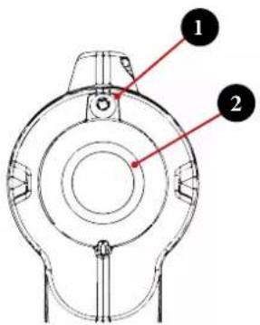
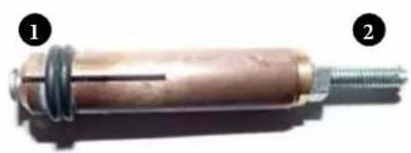
2) Locking/unlocking the force applied to the gun:
Unlock
Slightly loosen the Torx 20 screw (1)
Remove the cover (2)
Lock
Refit the cover (2) Lightly tighten the Torx 20 screw (1)
text_image
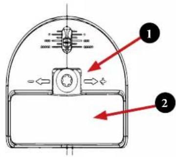
Technical diagram of a mechanical component with numbered parts labeled 1 and 23) Lock/unlock gun retraction:
Unlock
Slightly loosen the Torx 20 screw (1)
Remove the cover (2)
Lock
Refit the cover (2) Lightly tighten the Torx 20 screw (1)
text_image
Technical diagram of a mechanical component with labeled parts 1 and 2, showing internal structure and directional arrows.Notes: The guns are supplied with locked force and retraction settings. User locking is optional.
PREPARING THE GUN AND POWER SOURCE FOR STUD WELDING
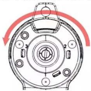
1) Remove the tripod ring
Make a quarter turn to the left
natural_image
Technical diagram of a circular mechanical component with internal parts and directional arrows (no text or symbols)Tripod in retracted position
natural_image
Technical line drawing of a mechanical component with no visible text or symbols2) Fitting the stud holder (Fig 15).
1) The head of the stud should protrude by about a millimetre. This space limits the quantity of molten material projected onto the stud holder.
2) Screw for adjusting the position of the stud. (Fig 15)
3) Unscrew the ring.
4) Insert the stud holder.
5) Tighten the ring securely (Fig 12.9).
natural_image
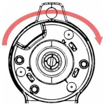
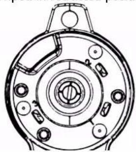
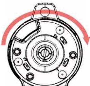
Close-up of a cylindrical mechanical component with a threaded end and central shaft, labeled with numbers 1 and 2 (no text or symbols on the object itself)3) Fitting the tripod ring with quarter-turn lock
Place the tripod in this position, then make a quarter turn to the right.
natural_image
Technical diagram of a mechanical component with red curved arrows indicating rotation or movement (no text or symbols)Tripod in correct position.
natural_image
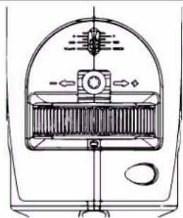
Technical line drawing of a circular mechanical component with multiple holes and a handle (no text or symbols)1) Force adjustment (Fig 12.10)
See (Fig 14) for the level of force required, according to the material and size of the stud.

text_image
Technical diagram of a mechanical component with labeled parts and directional arrows indicating rotation or movement.2) Retraction adjustment (Fig 12.4)
See (Fig 15) for the amount of retraction required, depending on the material and size of the stud.
natural_image
Technical line drawing of a mechanical component with no visible text or symbols3) Voltage settings (See Synergy settings) Voltage is adjustable from 50V to 200V. Use the arrow keys.
Note: if necessary, press the cancel button to exit the menu.
text_image
8884) Lock settings (Optional) See Fig 20 and 21.
5) Position the earth clamps.
Double earth clamps are supplied to avoid the effects of magnetic blow-out, it is advisable to position them equidistantly either side of the stud being welded.
WELDING STUDS
| 1) Place a stud in the stud holder.2) Position the gun so that the 3 contact points touch the metal sheet. If the stud holder has been correctly adjusted, the tip of the stud should touch the workpiece and the indicator light should come on (Fig 10.3)Note: the studs do not act as earth contacts.3) Once the gun is in a stable position, pull the trigger. | 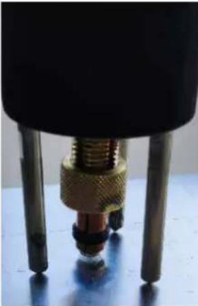 | |
| 4) Weld controlExample of a copper-plated steel M8 stud on a 1.2 mm steel sheet.Note: No residual heat traces should appear on the reverse side of the sheet. | 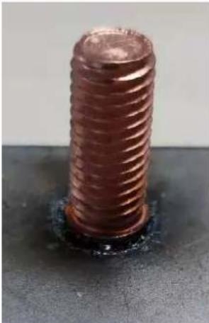 | |
| Important: Before running a full series of welds, carry out tests on a sample piece.See standard NF ISO 14555 for tests.For example: It must be possible to bend the stud to an angle of 30° without the weld failing. | 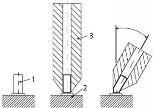 |
FAULTS
o Thermal protection:
When the thermal protection indicator is lit (see Fig 10.7), the user interface will be frozen. The fan will run to cool the power source, wait for the light to go out before the power source is ready for use again.
o Overvoltage protection
o Capacitor charging fault
- If the power source fails to charge the capacitors after 15 seconds, "DEF" should appear on the display.
o Trigger fault
- If the trigger is pressed when the power is switched on, "_-" should appear on the display.
o Gun-related errors
- Error 1 or 2: Incorrect stud displacement time.
- Error 3: In retraction mode, Spring setting too high,. the solenoid was unable to lift the stud.
POWER SOURCE THERMAL PROTECTION
The machine is provided with an automatic thermal protection system. This system will stop the machine to prevent it from overheating. In this situation, the yellow thermal fault indicator lights up.
| THERMAL SPECIFICATIONS | |
| Ambient operating temperature From +5°C to +40°C | |
| Ambient storage and transport temperature From -25°C to +55°C | |
WARRANTY
The warranty covers any defects or manufacturing faults for two years, from the date of purchase (parts and labour).
The warranty does not cover:
- Any other damage caused during transport.
- The general wear and tear of parts (i.e: cables, clamps, etc.).
- Incidents caused by misuse (incorrect power supply, dropping, disassembly).
- Faults due to the environment (pollution, rust, dust).
In the event of a fault, please return the appliance to your distributor, along with:
- a dated proof of purchase (receipt, invoice...)
a note explaining the malfunction.
SCHÉMA ÉLECTRIQUE / CIRCUIT DIAGRAM / SCHALTPLAN / DIAGRAMA ELECTRICO/ ЭЛЕКТРИЧЕСКАЯ СХЕМА / SCHEMA ELETTRICO / ELEKTRISCH SCHEMA
Electrical diagram of the generator :
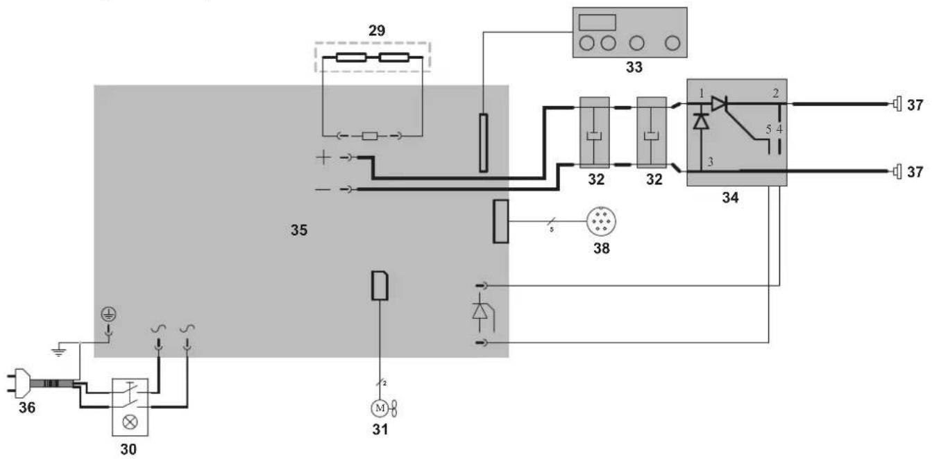
text_image
29 33 1 2 37 35 32 32 34 37 38 36 30 31 2Electrical diagram of the gun :
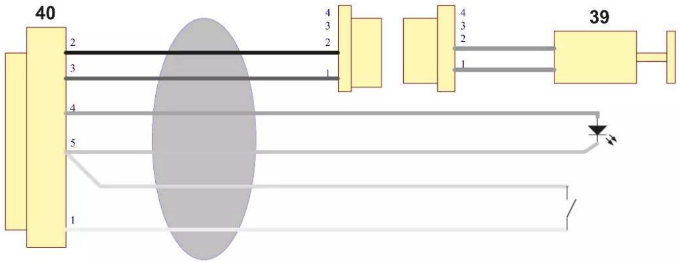
text_image
40 2 3 4 5 1 4 3 2 4 3 2 1 39PIECES DE RECHANGE / SPARE PARTS / ERSATZTEILE / PIEZAS DE RECAMBIO/ ЗАПЧАСТИ / PEZZI DI RICAMBIO / ONDERDELEN
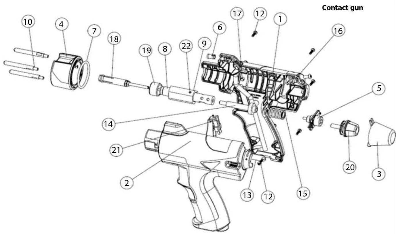
text_image
Contact gun 10 4 7 18 19 8 22 9 6 17 12 1 16 5 14 21 2 13 12 15 20 3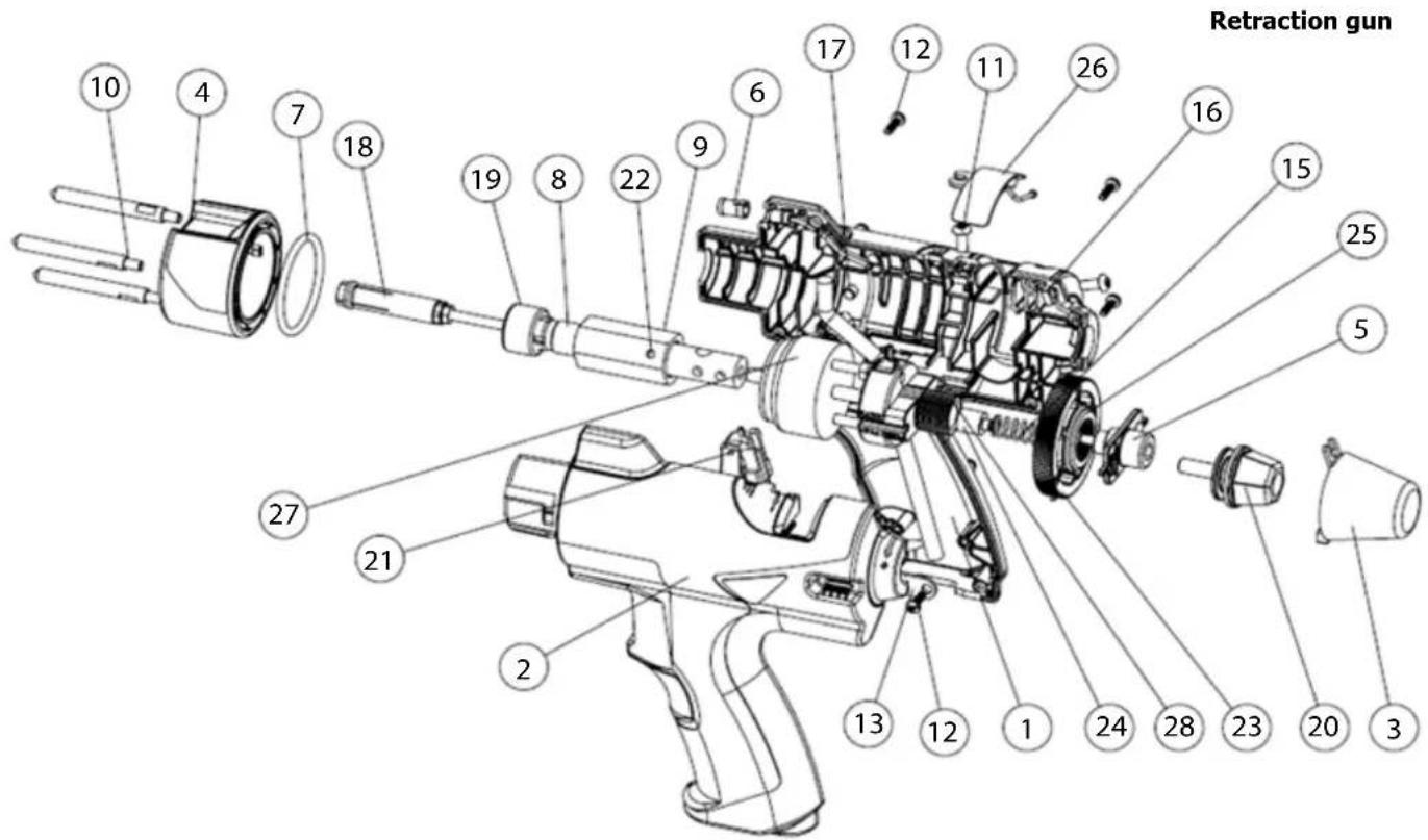
text_image
Retraction gun 10 4 7 18 19 8 22 9 6 17 12 11 26 16 15 25 5 27 21 2 13 12 1 24 28 23 20 3N° Qty Contact Retraction
| 1 Shell A retraction gun (capatek) 1 56324 56322 | ||||
| 2 Shell B retraction gun (capatek) 1 56325 56323 | ||||
| 3 Capatek gun force wheel cover 1 56329 | ||||
| 4 Capatek pistol tripod ring 1 56330 | ||||
| 5 Capatek gun force slider 1 56333 | ||||
| 6 Transparent LED cover 1 52020 | ||||
| 7 O-ring 37.46x3 NBR 90SH 1 51533 | ||||
| 8 Capatek main shaft 1 M0504 | ||||
| 9 Chuck collar | 1 90597 | |||
| 10 | Capatek mechanical gun pins | 3 | M0507 | |
| 11 | Mx screw M4x10 TCB TX20 zn black iso 7380-1 cl 8.8 | 1 | 43404 | |
| 12 | Plastic screw D3x10 TCBL TX10 zn black | 8 | 43413 | |
| 13 | Aluminium cable clamp | 1 | 99047Z | |
| 14 | Axe appui ressort | 1 | M0505 | |
| 15 | Steel compression spring | 1 55349 55350 | ||
| 16 | Square nut M4 7x7x3.2 DIN 557-5 | 1 | 42204 | |
| 17 | Mx screw M5x4 STHC H2.5 flat end zn white din 913 | 2 | 42180 | |
| 18 | Stud holder | 1 | Accessoires | |
| 19 | Aluminium tripod gun chuck nut | 1 90598 | ||
| 20 | Adjustment wheel Tripod aluspot gun + M6x30 TH screw | 1 | 56067 | |
| 21 | North trigger moving part | 1 56029 | ||
| 22 | Hardened cylindrical pin 5x18 crude steel din 6325 | 1 41323 | ||
| 23 | Capatek pistol travel adjustment wheel | 1 | 56326 | |
| 24 | Capatek solenoid shaft spring support stop for gun | 1 | 56327 | |
| 25 | Capatek pistol stroke adjustment wheel | 1 | 56326 | |
| 26 | Capatek pistol racing wheel guard | 1 | 56328 | |
| 27 | Solenoid push/pull 1 | 1 | 55339 | |
| 28 | Capatek pistol stroke slider | 1 | 56332 | |
PIECES DE RECHANGE / SPARE PARTS / ERSATZTEILE / PIEZAS DE RECAMBIO/ ЗАПЧАСТИ / PEZZI DI RICAMBIO / ONDERDELEN
text_image
Technical diagram of a robotic device with numbered components for identificationN° Designation Qty Contact Retraction
| 29 50W 68 ohms resistance 1 98630 | |||
| 30 Luminous orange switch (22/30) 0-I 1 52460 | |||
| 31 Ventilator 1 51048 | |||
| 32 PCB capacitor Aluspot 1 97156C | |||
| 33 Keyboard 1 51928 | |||
| 34 Thyristor module - 400A diode 1 52159 | |||
| 35 Managing PCB 1 E0178C | |||
| 36 Power cord 3x2.50 mm2 - H07RNF - 2.20m - EU plug 1 21462 | |||
| 37 Texas H21 Female subbase - CX0031 - Max. cross-section 70 mm2 - HF version | 1 | 51468 | |
| 38 faisceau 5 fils sur 7 | 1 71873 | ||
| 39 Solenoide | 1 | F0979 | |
| 40 Gun beam | 1 | F0945ST | F1024SF |
| 41 Earth cable Y | 1 | F0948 | F1021 |
| 42 Cable gland | 1 71148 | ||
| 43 Corner glide | 4 56163 | ||
| 44 Corner foot | 4 56120 | ||
ICÔNES / SYMBOLS / ZEICHENERKLÄRUNG / ICONOS / СИМВОЛЫ / PITTOGRAMMI / PICTOGRAMMEN
 | - Warning ! Read the instruction manual before use.- Caution ! Read the user manual.- Achtung! Lesen Sie die Betriebsanleitung.- iCuidado! Lea el manual de instrucciones antes de su uso.- Внимание! Прочтите инструкцию перед использованием.- Attenzione ! Leggere il manuale utente.- Let op! Lees aandachtig de handleiding. |
| A | Ampères - Amps - Ampere - Amperlos - Ампер - Amps - Ampere |
| V | Volt - Volt - Volt - Voltio - Вольт - Volt - Volt |
| Hz | Hertz - Hertz - Hertz - Hercio - Герц - Hertz - Hertz |
 | - Suitable for welding in an environment with an increased risk of electric shock. However, the machine itself should not be placed in such an environment. - Adapted for welding in environments with increased risk of electrical shock. However, the welding machine should not be placed in such places. - Geeignet für Schweißarbeiten im Bereich mit erhöhten elektrischen Risiken. Trotzdem sollte die Schweißquelle nicht unbedingt in solchen Bereichen betrieben werden. - Adaptado a la soldadura en un entorno que comprende riesgos de choque eléctrico. La fuente de corriente ella misma no debe estar situada dentro de tal locales. - Подходит для сварки в среде с повышенной опасностью удара электрическим током. Тем не менее не следует ставить источник тока в такие помещения. - Geschikt voor het lassen in een ruimte met verhoogd risico op elektrische schokken. De voedingsbron zelf moet echter niet in dergelijke ruimte worden geplaatst. - È consigliato per la saldatura in un ambiente con grandi rischi di scosse elettriche. La fonte di corrente non deve essere localizzata in tale posto. |
| IP21 | - Protégé contre l'accès aux parties dangereuses avec un dolgt, et contre les chutes verticales de gouttes d'eau- Protected against rain and against fingers access to dangerous parts- Geschützt gegen Berührung mit gefährlichen Teilen und gegen senkrechten Wassertropfenfall- Protegido contra el acceso a partes peligrosas con el dedo y contra las caldas verticales de gotas de agua- Защищен от доступа пальцев в опасные части, а также от попадения вертикальных капель воды- Beveiligd tegen de toegang tot gevaarlijke delen met een vinger, en tegen verticala vallende waterdruppels- Protette contro pioggia e contro l'accesso delle dita in parti pericolose+ |
 | Tension d'alimentation assignée - Rated power supply voltage - Nennspannung - Tensión de alimentación asignada - Номинальное напряжение питания - Nominale voedingsspanning - Tensione di alimentazione nominale |
 | Puissance permanente (au facteur de marche de 100%) - Permanent power (at a 100% duty cycle) - Dauerleistung (@ 100%) - Potencia permanente (al ciclo de trabajo de 100%) - Постоянная мощность (при ПВ 100%) - Permanent vermogen (bij een inschakelduur van 100%) - Potenza permanente (al fattore di marcia de 100%) |
 | Courant maximal de court-circuit secondaire - Maximal current of a secondary short circuit - Maximaler sekundärer Kurzschlussstrom - Corriente máxima de cortocircuito secundario - Максимальный ток короткого замыкания на вторичке - Secondaire maximale kortsluitingsstroomsterkte - Corrente massima di corto-circuito secondario |
| [KDBG] | Courant permanent au secondaire - Continuous secondary current - Dauerstrom an der Sekundärseite - Corriente continua secundaria - Непрерывный вторичный ток - Continue secundaire stroom - Corrente secondaria continua |
| m | Masse de la machine - Machine weight - Masse der Maschine - Peso de la máquina - Bec машины - Gewicht machine - Peso della macchina |
| Courant de soudage continu - Direct welding current - Gleichschweißstrom - Corriente continua de soldadura - Continue lasstroom - Corrente di saldatura continua | |
 | - Matériel conforme aux Directives européennes. The EU Declaration of Conformity is available on our website (see cover page).- Device complies with european directives, The EU declaration of conformity is available on our website (see cover page).- Gerät entspricht europäischen Richtlinien. Die Konformitätserklärung finden Sie auf unsere Webseite.- Aparato conforme a las directivas europeas. La declaración de conformidad UE está disponible en nuestra página web (dirección en la portada).- Устройство соответствует директивам Евросокоза. Декларация о соответствии доступна для просмотра на нашем сайте (ссылка на обложке).- Apparaat in overeenstemming met de Europese richtlijnen. De verklaring van overeenstemming is te downloaden op onze website (adres vermeld op de omslag).- Materiale in conformità alle Direttive europee. La dichiarazione di conformità è disponibile sul nostro sito (vedere sulla copertina). |
 | - EAEC Conformity marking (Eurasian Economic Community).- Conformity mark EAC (Eurasian Economic Commission).- EAC-Konformitätszeichen (Eurasische Wirtschaftsgemeinschaft).- Marca de conformidad EAC (Comunidad económica euroasiática).- Маркировка соответствия EAC (Евразийское экономическое сообщество).- Marchio conformità EAC (Commissione economica euasiatica).- EAC (Euraziatische Economische Gemeenschap) merkteken van overeenstemming |
 | - Matériel conforme aux exigences britanniques. • The UK Declaration of Conformity is available on our website (see cover page).- Equipment in compliance with British requirements. The British Declaration of Conformity is available on our website (see home page).- Das Gerät entspricht den britischen Richtlinien und Normen. Die Konformitätserklärung für Grossbritannien ist auf unserer Internetseite verfügbar (siehe Titelseite).- Equipo conforme a los requisitos británicos. La Declaración de Conformidad Británica está disponible en nuestra página web (véase la portada).- Материал соответствует требованиям Великобритании. Заявление о соответствии для Великобритании доступно на нашем веб-сайте (см. главную страницу).- Materiaal conform aan de Britse eisen. De Britse verklaring van overeenkomt is beschikbaar op onze website (zie omslagpagina).- Materiale conforme alla esigenze britanniche. La dichiarazione di conformità britannica è disponibile sul nostro sito (vedere pagina di copertina). |
 | - CMIM : Certification Marocaine- CMIM : Moroccan Certification- CMIM : Marokkanische Zertifizierung- CMIM : Certificación Marroquí- CMIM : - CMIM : Марокканская сертификация- CMIM : Marokkaanse certificering- CMIM : Certificazione Marocchina |
| ISO 669:2016 | La source de courant de soudage est conforme aux normes IEC62135-1 et EN ISO 669 - The welding current source complies with IEC62135-1 and EN ISO 669 standards- Die Schweißstromquelle entspricht den Normen IEC62135-1 und EN ISO 669 - El generador de soldadura cumple las normas IEC62135-1 y EN ISO 669 - Источник сварочного тока соответствует стандартам IEC62135-1 и EN ISO 669 - De lasgenerator voldoet aan de IEC62135-1 en EN ISO 669 normen - La sorgente di corrente di saldatura è conforme alle norme IEC62135-1 e EN ISO 669 |
 | - L'arc électrique produit des rayons dangereux pour les yeux et la peau (protégez-vous!).- The electric arc generates rays that are dangerous to the eyes and skin (protect yourself!).- Der elektrische Lichtbogen verursacht Strahlungen auf Augen und Haut (Schützen Sie sich!).- El arco eléctrico produce radiaciones peligrosas para los ojos y la piel. Protéjase.- Электрическая дуга дает излучение опасное для глаз и кожи (носите защитную одежду!).- L'arco elettrico produce raggi pericolosi per gli occhi e la pelle (proteggersi!),- Booglassen kan gevaarlijk zijn en ernstige en zelfs dodelijke verwondingen veroorzaken.- This product should be disposed of at an appropriate recycling facility. Do not dispose of in domestic waste.- Separate collection required, Do not throw in a domestic dustbin.- Für die Entsorgung Ihres Gerätes gelten besondere Bestimmungen (Sondermüll). Es darf nicht mit dem Hausmüll entsorgt werden.- Este producto es objeto de una colecta selectiva - Ne lo tire a la basura doméstica.- Этот аппарат подлежит утилизации - Не выбрасывайте ero в домашний мусоропровод.- E’ richiesta una raccolta differenziata, non gettare in un bidone della spazzatura domestica.- Afzonderlijke inzameling vereist volgens de Europese richtlijn 2012/19/UE. Gooi het apparaat niet bij het huishoudelijk afval ! |
 | - This product should be recycled appropriately- This product should be recycled appropriately.- Recyclingprodukt, das gesondert entsorgt werden muss.- Producto reciclable que requiere una separación determinada.- Этот аппарат подлежит утилизации.- Product recyclebaar, niet bij het huishoudelijk afval gooien.- Prodotto riciclabile soggetto a raccolta differenziata. |
| ### | - Temperature information (thermal protection)- Temperature information (thermal protection)- Information zur Temperatur (Thermoschutz)- Información sobre la temperatura (protección térmica)- Информация по температуре (термозащита)- Informazioni temperatura (protezione termica)- Informatie over de temperatuur (thermische beveiliging) |
I. GENERATOR ABB. 1

text_image
Technical diagram of an electronic device with labeled components, showing front and side views with numbered parts.text_image
1 2 3 888 ← → ← ← 678text_image
Labeled diagram of a welding torch with numbered parts for identification and assembly reference.text_image
Technical diagram of a mechanical component with numbered parts labeled 1 and 2text_image
Technical diagram of a mechanical component with labeled parts and directional arrows indicating assembly or flow.natural_image
Technical diagram of a mechanical device with numbered components and red motion arrows indicating rotation (no text or symbols)natural_image
Technical line drawing of a mechanical component with no visible text or symbolsnatural_image
Close-up of a cylindrical mechanical component with threaded end and metallic housing (no visible text or symbols)natural_image
Technical diagram of a mechanical component with red curved arrows indicating rotational motion (no text or symbols)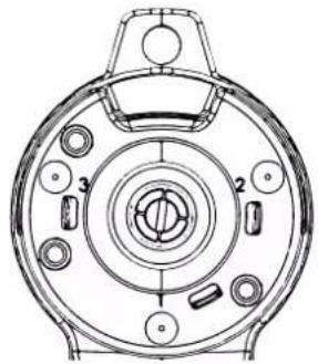
natural_image
Technical line drawing of a circular mechanical component with numbered parts (no text or symbols)text_image
Technical diagram showing a mechanical component with labeled parts and directional arrows indicating rotation or movement.natural_image
Technical line drawing of a mechanical device with no visible text or symbolsWÄRMESCHUTZ DES GENERATORS
text_image
Technical diagram of a mechanical device with numbered components for identificationtext_image
Technical diagram of an electronic device with labeled components, showing front and side views with numbered parts.text_image
1 2 3 888 ← → ← ← 678text_image
Technical diagram of a handheld electric gun with numbered parts and labeled connectorsWAARSCHUWINGEN - VEILIGHEIDSINSTRUCTIES
ALGEMENE INSTRUCTIES