
ACSOL2B - Solar panel Lorex - Free user manual and instructions
Find the device manual for free ACSOL2B Lorex in PDF.

| Product Type | Solar Panel |
| Brand | Lorex |
| Model | ACSOL2B |
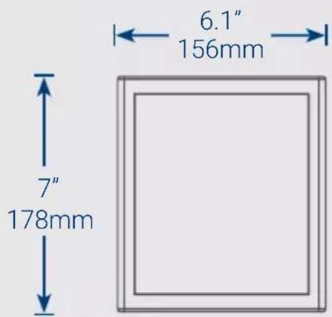
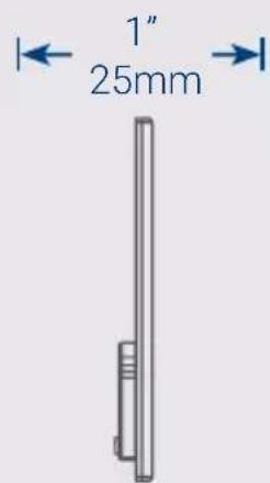
| Panel Dimensions | 178 x 156 x 25 mm (7 x 6.1 x 1 in) |
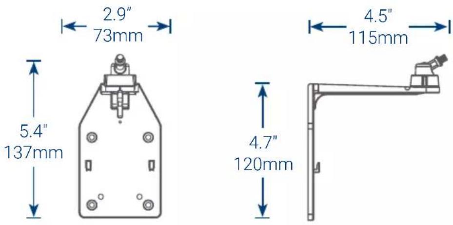
| Wall Mount Dimensions | 137 x 115 x 73 mm (5.4 x 4.5 x 2.9 in) |
| Rated Power | 1 W |
| Power Cable Length | 3 m (10 ft) |
| Adjustable Angle | Yes, via adjustment ring |
| LED Indicator | Red LED on back (charging indicator) |
| Compatibility | Lorex wireless cameras with power port |
| Package Contents | Solar panel, wall mount, mounting template, 4 screws and anchors, 2 adjustment ring screws, 6 mm drill bit, 3 cable guides and screws, Velcro strap |
| Maintenance | Clean with a soft cloth and warm water |
| Installation | Two options: separate or with camera |
| Operating Environment | Outdoor, exposed to direct sunlight |
| Warranty | See policy at lorex.com/warranty |
| Compliance | FCC Part 15 |
| Required Tools (not included) | Drill, Phillips screwdriver |
Frequently Asked Questions - ACSOL2B Lorex
User questions about ACSOL2B Lorex
0 question about this device. Answer the ones you know or ask your own.
Ask a new question about this device
Download the instructions for your Solar panel in PDF format for free! Find your manual ACSOL2B - Lorex and take your electronic device back in hand. On this page are published all the documents necessary for the use of your device. ACSOL2B by Lorex.
USER MANUAL ACSOL2B Lorex
• Solar panel with 10ft (3m) power cable
- Wall mount
- Wall mount template
• Wall mount screws & anchors (×4)
- Adjustment ring screws (x2)
• 1/4" (6mm) Drill bit for cement and wood
• Cable guides, screws & anchors (×3)
- Velcro cable tie
User-supplied tools
- Drill
- Phillips screwdriver
Dimensions
Wall mount
Front and side view
Solar panel
Front and side panel
Position the solar panel
- The solar panel produces power only when exposed to sunlight. You will need to choose a location with plenty of direct sunlight.
- To achieve the best charging performance, angle the solar panel towards the sun. The optimal angle varies throughout the year, depending on the seasons and your location. As a general guideline, the solar panel should be facing the equator; in the northern hemisphere, the solar panel faces south and in the southern hemisphere, the solar panel faces north.
- Make sure the red LED indicator on the back of the solar panel turns on (see Figure 1). If the LED turns on, the solar panel is receiving enough light to maintain the camera battery pack's charge.
Tip: Periodically clean the solar panel with a soft cloth and warm water to keep the surface clear.
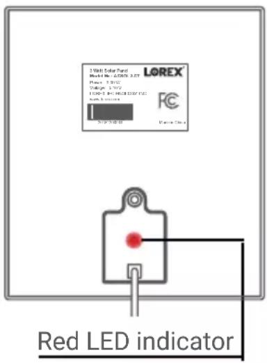
Figure 1: Back panel
Select your installation method
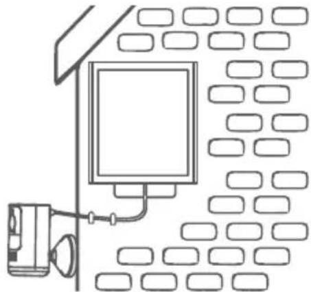
Option A (recommended): Installing the solar panel separately
natural_image
Line drawing of a room with a monitor and wall-mounted device (no text or symbols)Install your wire-free camera and solar panel separate from each other, see pages 5-7.
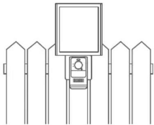
Option B: Installing the solar panel and camera together
natural_image
Line drawing of a fence with a mounted digital camera and monitor, no text or symbols presentInstall your wire-free camera directly onto the solar panel, see pages 8-11.
ATTENTION: For option B, the camera and solar panel should be installed facing the residence. If the camera is installed backing onto the residence, the wall mount may block the wireless signal.
Option A - Installing the solar panel separately
-
The solar panel is designed to maintain the camera battery pack's charge. Make sure to first charge the battery pack using the micro USB cable.
-
Stick the wall mount template in the desired mounting position.
-
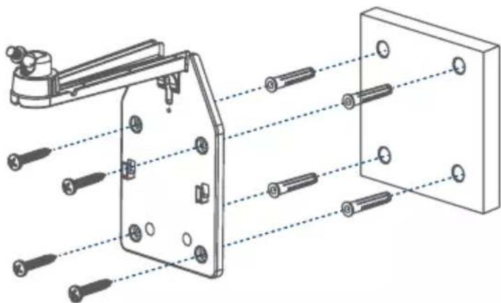
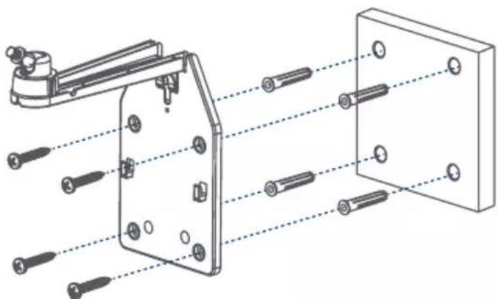
Drill into the wall mount template's marked holes using the 1/4" (6mm) drill bit. If attaching to masonry, gently tap four anchors into the holes.
-
Secure the wall mount using four screws (see Figure 1).
natural_image
Technical diagram of a mechanical assembly with numbered components and alignment lines (no text or symbols)Figure 1
Option A - Installing the solar panel separately
- Loosen the wall mount's adjustment ring by turning it counterclockwise (see Figure 2).
- Angle the rotating adjustment screw 45^ away from the mounting surface (see Figure 2).
- Twist the solar panel onto the wall mount. Be careful not to hit the mounting surface.
- Adjust the angle of the solar panel to receive direct sunlight, then tighten the adjustment ring.
- Use a Phillips screwdriver and the adjustment ring screw to secure the adjustment ring from underneath the wall mount (see Figure 2).
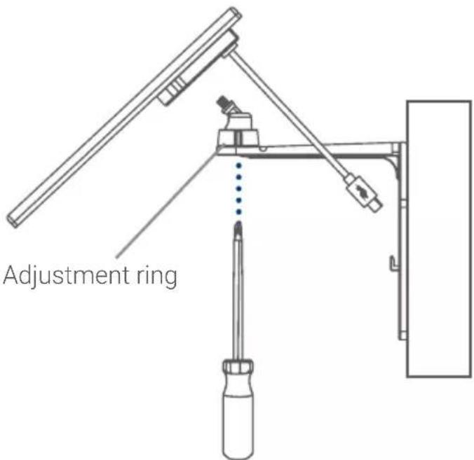
Figure 2
- Run the solar panel's power cable along the cable guide on the wall mount arm (see Figure 3).
- Pull up the power port cover on the back of your camera.
- Use the solar panel's power cable to connect to the power port (see Figure 3).
Optional cable management:
- Use the adjustable Velcro cable tie to secure cords and organize any clutter.
- Secure the solar panel's 10ft (3m) power cable to the wall using the cable guides, screws, and anchors as needed (see Figure 4).
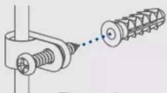
natural_image
Technical illustration of a mechanical assembly with threaded components and a separate spiral component (no text or symbols)Figure 4
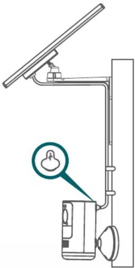
natural_image
Diagram of a vertical utility pole with a device and a magnified inset showing a small object (no text or symbols present)Figure 3
Option B - Installing the solar panel and camera together

ATTENTION: The camera can be installed onto the solar panel only if the camera is facing the residence. If the camera is installed backing onto the residence, the wall mount may block the wireless signal. We recommend installing the solar panel and camera separately, see pages 5-7.
-
The solar panel is designed to maintain the camera battery pack's charge. Make sure to first charge the battery pack using the micro USB cable.
-
Stick the wall mount template in the desired mounting position.
-
Drill into the wall mount template's marked holes using the 1/4" (6mm) drill bit. If attaching to masonry, gently tap four anchors into the holes.
-
Secure the wall mount using four screws (see Figure 1).
natural_image
Technical diagram of a mechanical assembly with multiple bolted components and alignment lines (no text or labels)Figure 1
-
Loosen the wall mount's adjustment ring by turning it counterclockwise (see Figure 2).
-
Angle the rotating adjustment screw 45^ away from the mounting surface (see Figure 2).
-
Twist the solar panel onto the wall mount. Be careful not to hit the mounting surface.
-
Adjust the angle of the solar panel to receive direct sunlight, then tighten the adjustment ring.
-
Use a Phillips screwdriver and the adjustment ring screw to secure the adjustment ring from underneath the wall mount (see Figure 2).
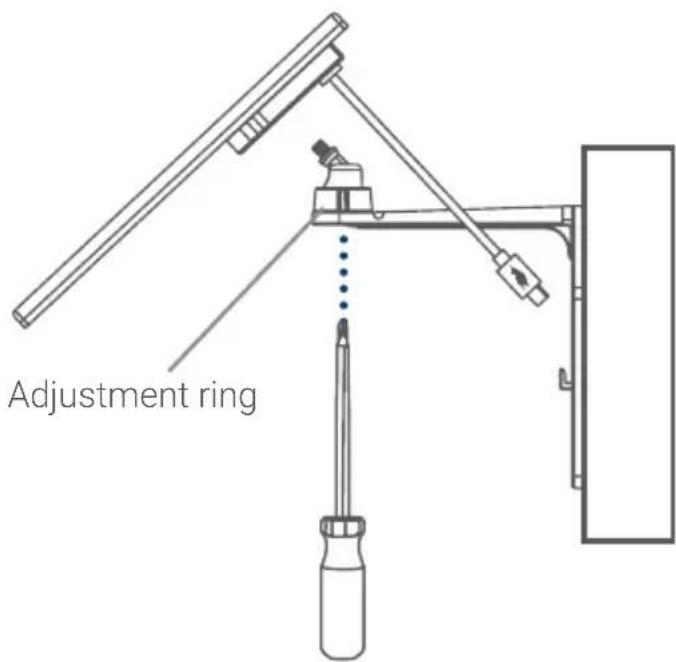
Figure 2
Option B - Installing the solar panel and camera together
- Use a Phillips screwdriver and two screws to attach the camera's mounting plate to the wall mount (see Figure 3).
- Align the four tabs from the camera's bracket with the four slots on the mounting plate (see Figure 4).
- Push down to lock the camera.
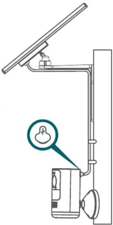
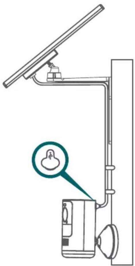
- Run the solar panel's power cable along the cable guide on the wall mount arm (see Figure 3).
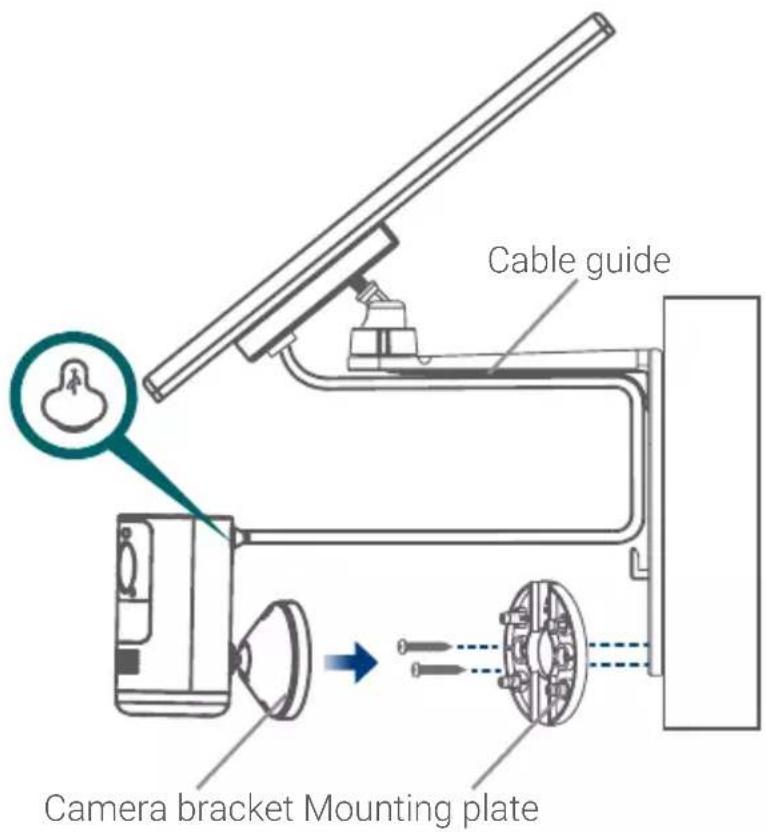
Figure 3
- Pull up the power port cover on the back of the camera.
- Use the solar panel's power cable to connect to the camera's power port (see Figure 3).
Optional cable management:
Use the adjustable Velcro cable tie to secure cords and organize any clutter.
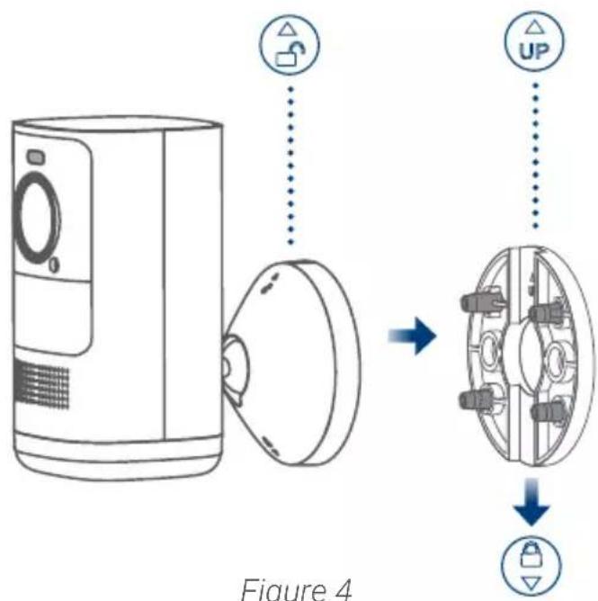
Figure 4
Need help?
Visit help.lorex.com for up-to-date information and resources:
- Register your product
- Download product guides
- Watch how-to-videos
• Find related troubleshooting tips & FAQs
Please see our full Terms of Service and Limited Hardware Warranty Policy at lorex.com/warranty.

This device complies with part 15 of the FCC Rules. Operation is subject to the following two conditions: (1) This device may not cause harmful interference, and (2) This device must accept any interference received, including interference that may cause undesired operation.
Copyright © 2021 Lorex Corporation
As our products are subject to continuous improvement, Lorex reserves the right to modify product design, specifications and prices, without notice and without incurring any obligation. E&OE. All rights reserved.
ACSOL2_QSG_TRILINGUAL_R1
LOREX®
Panneau solaire
natural_image
Simple line drawing of a monitor mounted on a wall with a camera and cable, surrounded by empty rectangular compartments (no text or symbols)natural_image
Line drawing of a fence with a mounted digital camera (no text or symbols)natural_image
Technical diagram of a mechanical assembly with numbered components and alignment lines (no text or symbols)Figure 1
natural_image
Technical illustration of a mechanical assembly with threaded components and a spring-like component (no text or symbols)Figure 4
natural_image
Technical line drawing of a vertical support structure with a magnified inset showing a small object (no text or symbols)Figure 3
natural_image
Technical line drawing of a mechanical assembly with multiple bolted components and alignment lines (no text or symbols)Figure 1
Copyright © 2021 Lorex Corporation
natural_image
Simple line drawing of a monitor mounted on a wall with a small device nearby (no text or symbols)natural_image
Line drawing of a mounted device mounted on a fence, no text or symbols presentnatural_image
Technical diagram of a mechanical assembly with numbered components and alignment lines (no text or symbols)Figura 1
natural_image
Technical illustration of a mechanical assembly with threaded components and a spring-like component (no text or symbols)Figure 4
natural_image
Technical line drawing of a vertical-mounted device with a magnified inset showing a small object (no text or symbols present)Figura 3
natural_image
Technical diagram of a mechanical assembly with multiple bolted components and alignment lines (no text or labels)Figura 1
Copyright © 2021 Lorex Corporation