
HI4000P - Heating BOSCH - Free user manual and instructions
Find the device manual for free HI4000P BOSCH in PDF.

User questions about HI4000P BOSCH
0 question about this device. Answer the ones you know or ask your own.
Ask a new question about this device
Download the instructions for your Heating in PDF format for free! Find your manual HI4000P - BOSCH and take your electronic device back in hand. On this page are published all the documents necessary for the use of your device. HI4000P by BOSCH.
USER MANUAL HI4000P BOSCH
natural_image
Simple line drawing of a rectangular block with rounded corners (no text or symbols)Table of contents 1 Explanation of symbols and safety instructions
1 Explanation of symbols and safety instructions ..... 10
1.1 Explanation of symbols .... 10
1.2 General safety instructions .... 10
2 Product Information .... 11
2.1 Declaration of conformity....11
2.2 Scope of delivery .... 11
2.3 Definition ....11
2.4 Intended use....12
2.5 Product description .... 12
2.6 Product identification .... 12
3 Commissioning....12
4 Preconditions for installation....12
4.1 Installation location requirements ..... 12
5 Installation ....12
6 Cleaning....14
7 Troubleshooting....14
8 Environmental protection and disposal .... 15
9 Data Protection Notice ....15
10 Technical information and reports .... 16
10.1 Technical Data .... 16
10.2 Product data for energy consumption ..... 16
11 Service addresses ....17
1.1 Explanation of symbols
Warnings
In warnings, signal words at the beginning of a warning are used to indicate the type and seriousness of the ensuing risk if measures for minimizing danger are not taken.
The following signal words are defined and can be used in this document:

DANGER
DANGER indicates that severe or life-threatening personal injury will occur.

WARNING
WARNING indicates that severe to life-threatening personal injury may occur.

CAUTION
CAUTION indicates that minor to medium personal injury may occur.
NOTICE
NOTICE indicates that material damage may occur.
Important information

The info symbol indicates important information where there is no risk to people or property.
1.2 General safety instructions
⚠️ Notices for the target group
These installation instructions are intended for gas, plumbing, heating and electrical contractors. All instructions must be observed. Failure to comply with instructions may result in material damage and personal injury, including danger to life.
▶ Read the installation, service and commissioning instructions (heat source, heating controller, pumps, etc.) before installation.
▶ Observe the safety instructions and warnings.
▶ Follow national and regional regulations, technical regulations and guidelines.
▶ Record all work carried out.
⚠ Safety of electrical appliances for domestic use and similar purposes
The following guidelines apply in accordance with EN 60335-1 and EN 60335-2-30 in order to prevent hazards when using electrical space heaters:
"Children younger than 3 years of age must be kept away from the appliance, unless continuously supervised. Children between 3 and 8 years of age must only switch the appliance on and off if they are supervised or have been shown how to use the appliance safely and have understood the associated dangers, provided that the appliance is positioned or installed in its normal place of use. Children between 3 and 8 years of age must not insert the plug into the socket, adjust the appliance, clean the appliance and/or not carry out the maintenance by the user."
"If the power cable is damaged, in order to avoid hazards it must be replaced by the manufacturer or its customer service department or a similarly qualified person."
△ Installation and use
▶ Do not install the device below a socket or near curtains or other combustible materials.
▶ Do not use the heating near a bathtub, shower or swimming pool.
▶ Do not use the product in small rooms if these are used by persons who are not able leave the room by themselves, unless the room is continuously monitored.
Hot surface
Some parts of this product can become very hot and inflict burns when they come into contact with the skin. Proceed with extreme caution if children and vulnerable adults are present.
⚠️ Risk of overheating, risk of fire
To reduce the risk of fire:
▶ Do not place anything on the panel. Do not cover the appliance or climb onto it.
▶ Ensure that the heat transfer from the panel is unhindered.
▶ Fasten the product to the wall or ceiling (with the exception of ceramic variants and glass variants with 800W or greater).
⚠️ Danger to life from electric shock!
Touching a defective product or connecting lead may result in electric shock.
▶ Do not use the product if it has been dropped.
▶ Do not use the product if there are visible signs of damage.
▶ Do not open the product.
▶ Avoid carrying out any interventions.
- Stop using the product and disconnect it from the mains power supply.
▶ Please contact Service.
You can find the service addresses in chapter 11, page 17.
-or-
▶ Dispose of the product properly.
⚠ System malfunctions caused by third-party equipment
This heat source is designed for operation with our control units.
System malfunctions, malfunctions and defects of system components resulting from the use of third-party equipment are excluded from liability.
Service work required to repair the damage will be invoiced.
i
According to the EU Directive 2009/125/EC - defined for the product area of individual room heaters in Regulation 2015/1188 - the operation of this infrared heater as a stationary individual room heater is only permitted if certain control/regulation requirements such as weekday control and window-open detection or, for example, adaptive control of the start of heating are met. Detailed information on this can be found, for example, on the Internet under: https://eur-lex.europa.eu/legal-content/DE/TXT/?qid=1596981415120&uri=CELEX:32015R1188.
To meet the above requirements and ensure comfortable operation of this infrared heating system, select one of the corresponding control components offered by Bosch (Bosch C-IR 20) or use an existing system that meets these criteria.
Electrical work
The panel is fitted with a three-conductor cable for 1/N/PE 230V/50Hz with a plug for connection into a socket.
Electrical work must only be carried out by electrical installation contractors.
Before starting electrical work:
▶ Isolate all poles of the mains voltage and secure against reconnection.
▶ Make sure the mains voltage is disconnected.
The panel is fitted with a overheating protection.
i
The removal of the plug and shortening of the supply lead will not result in loss of warranty. However, this must be performed by a technical qualified person.
The supply cable must be fitted with a device for disconnection from the mains voltage in which the distance between the disconnected contacts is at least 3 mm for all poles.
If the supply cable of this appliance is damaged, it has to be replaced by the producer or a service technician.
2 P r o d u c t
I n
These instructions contain important information for the system user regarding safe operation of the Infrared panel.
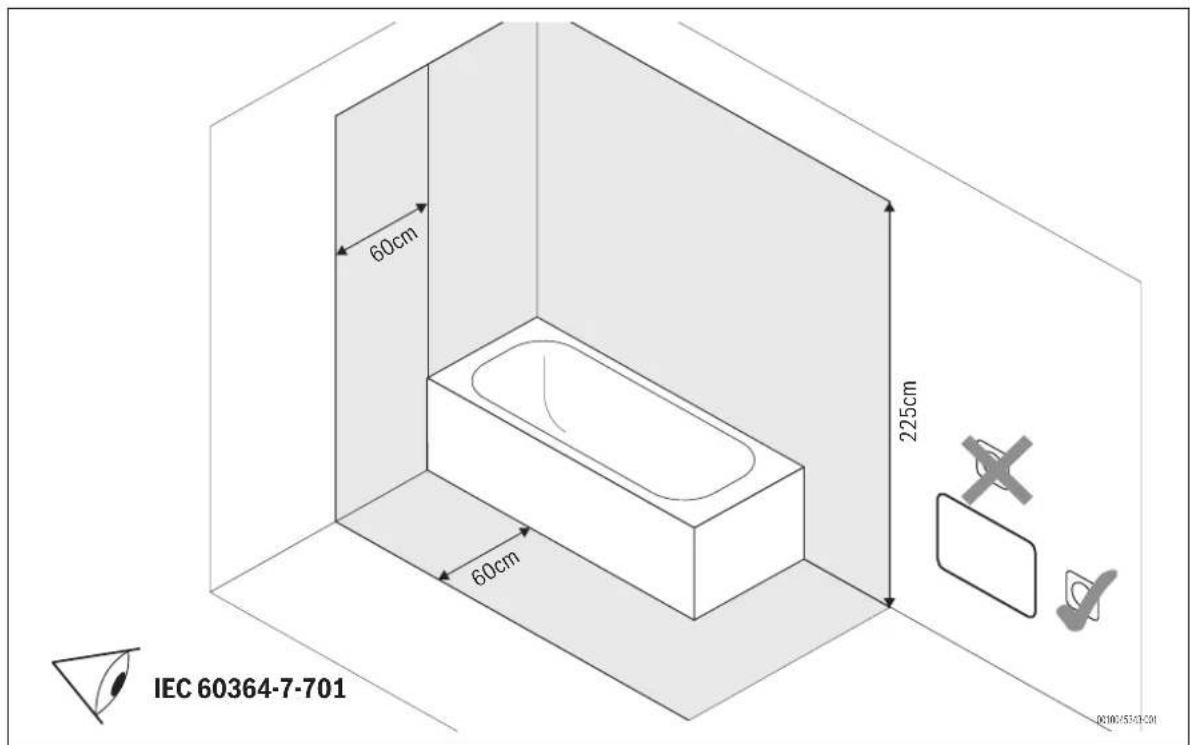
The appliance must only be set up or mounted outside the safety zone (shown in grey → Fig. 7, page 74).
For this:
▶ observe the installation instructions.
2.1 Declaration of conformity
The design and operating characteristics of this product comply with the European and national requirements.
CE The CE marking declares that the product complies with all the applicable EU legislation, which is stipulated by attaching this marking.
The complete text of the Declaration of Conformity is available on the Internet: worcester-bosch.co.uk.
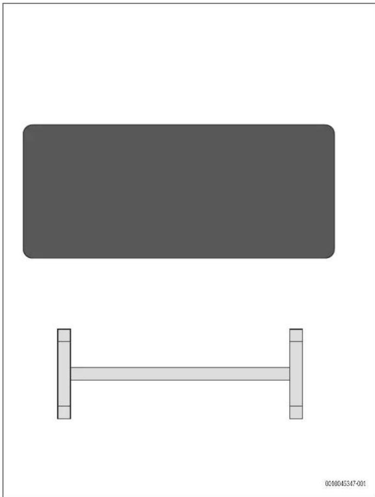
2.2 Scope of delivery
The scope of delivery is shown in Fig. 1 at the end of the document.
▶ Check packaging upon receipt of delivery for damage.
▶ Check the scope of delivery for completeness.
[1] Infrared panel
[2] Mounting frame
[3] Power supply cable
Technical documentation
i
Be sure to observe the requirements for the environmentally sound design of individual room heaters according to Commission Regulation (EU) 2015/1188.
According to this regulation, the operation of the infrared panel is only permitted with an additional controller that can implement the functions required in the regulation.
This controller must contain at least the electronic room temperature control and weekday control as well as at least one further function required by the directive, such as room temperature control with detection of open windows or adaptive control of the start of heating.
Here we recommend the Bosch C-IR 20.
i
The panel is fitted with a limit thermostat which ensures its safe operation.
2.3 Definition
The Infrared panel is subsequently referred to in this document as "product", "panel" or "appliance".
2.4 Intended use
The infrared panel is intended for heating of living spaces.
▶ Comply with the connection conditions in accordance with the specifications, standards and regulations of the relevant country.
▶ The appliance must only be set up or mounted outside the safety zone (shown in grey → Fig. 7, page 74).
Any other purpose is considered improper use. Any damage that results from such use is excluded from liability.
2.5 Product description
The Infrared panel is a wall mounted or ceiling mounted electric space heating plate.
i
Ceiling mounting is only allowed to be performed by an expert.
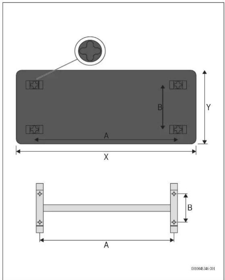
Dimensions
The dimensions are shown in Fig. 4 at the end of the document.
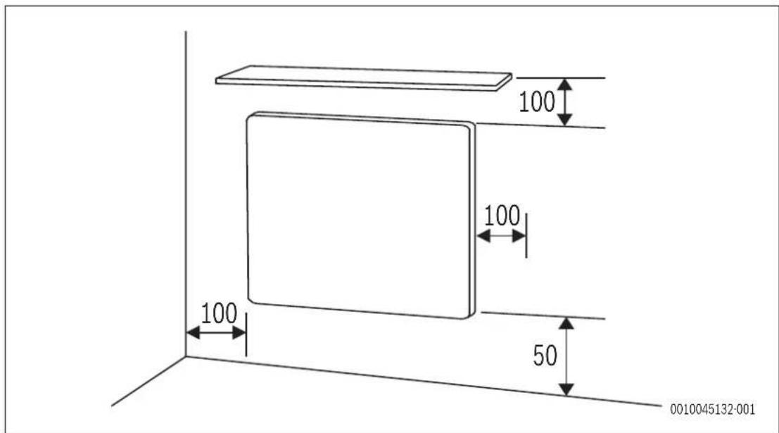
Clearances
The clearances are shown at the end of the document and in page 12). Regarding the vertical mounting (Fig. 5), the distance between the bottom edge of the appliance and the floor must not be less than 50mm (150mm is recommended). The clearance distance on the side must be at least 50 mm and 50mm is the minimum in the upward direction. There must be at least 50 cm of free space in front of the panel.
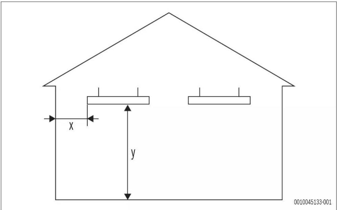
Table 12 Distances for ceiling mounting (Fig. 6)
2.6 Product identification
Data plate
The data plate contains performance data, approval data and the serial number of the product.
The data plate can be found on the backside of the product.
3 Commissioning
If the appliance is installed or set up in or was previously stored in a much colder environment, it must be allowed to adjust to the room temperature.
▶ Wait half an hour before switching on the appliance.
i
When the appliance is heating for the first time, it may emit a slightly unpleasant odour (for 2 hours at the most) which is caused by the product residues drying out.
4 Preconditions for installation
4.1 Installation location requirements
Surface temperature
The maximum surface temperature of the appliance is up to 110°C. Therefore no special safety measures are required to protect flammable materials and fitted furniture. Country-specific regulations must be observed.
Wall structure
The wall used for installation of the appliance must be load-bearing and the appliance must be able to rest on it over the entire surface.
Protection zones in damp areas
Observe the clearances for damp areas in Fig. 5 at the end of the document.
i
Observe all the current applicable national and regional regulations as well as all technical rules and guidelines. These may contain additional or deviating requirements for installations in damp areas.
▶ Do not install any switches, sockets or devices with mains power supply in the protection zones.
▶ Connect device to a residual current circuit breaker.
▶ Use only control units with suitable IP rating.
5 Installation
Installation on the wall/ceiling for glass and metallic panel
The glass and metallic version of the heater can be installed on the wall or on the ceiling. Note that, only the glass version of up to 800W can be installed in the ceiling.
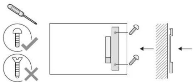
▶ Use the installation frame included in the scope and mark four points for the screws on the wall/ceiling.
▶ Drill the holes and insert appropriate dowels.
▶ Using four flat-headed screws, fix the installation frame on the wall/ceiling.
▶ Hang the panel on the installation frame.
▶ Use four nuts screwed on the bolts on the back of the panel to firmly support the panel against the wall/ceiling.
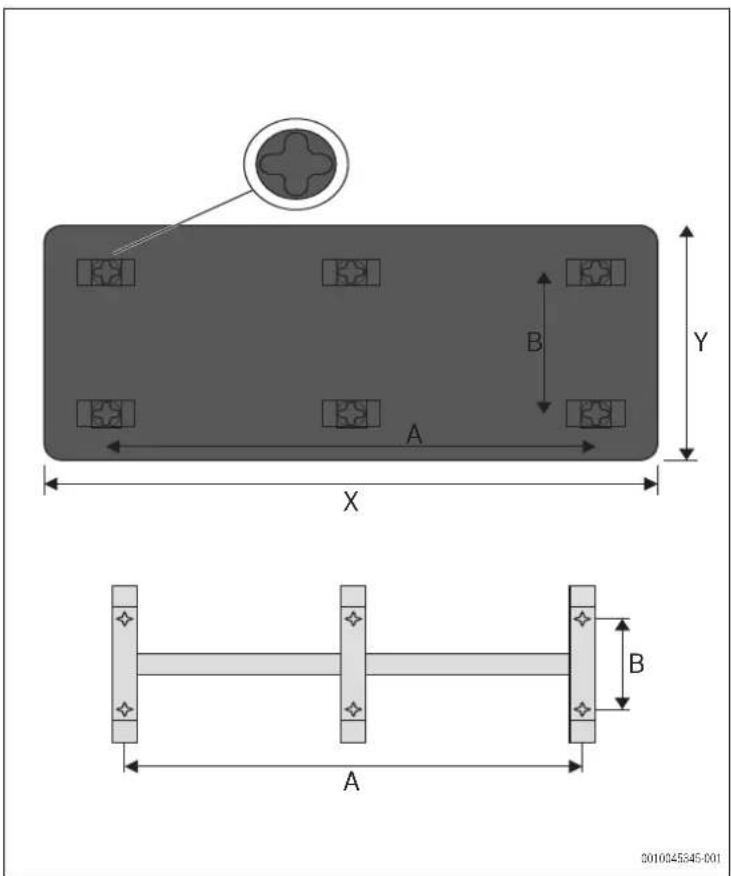
i
Mark six points for the screws on the glass panel of 850W, as seen in Fig. 4 at the end of the document. Use the fixing frame with six points for ceiling mounting.
| W A (mm) B (mm) | ||
| 300W 585 | 585 | |
| 500W 1200 400 | ||
| 700W 1185 585 | ||
| 850W 1185 785 |
Table 13 Distances for the glass panel (Fig. 3 up to 700W, Fig. 4 for the 850W version)
| W A (mm) B (mm) | ||
| 300W 340 | 280 | |
| 500W 885 | 115 | |
| 700W 660 | 280 | |
| 850W 383/766 | 280 |
Table 14 Distances for the fixing frame for glass panel
300W 340 360 592 592
500W 640 360 892 592
700W 940 360 1192 592
850W 940 360 1192 800
1000W 940 360 1192 850
Table 15 Distances for the metallic panel (Fig. 3)
| 300W 340 | 280 | |
| 500W 640 | 280 | |
| 700W 940 | 280 | |
| 850W 940 | 280 | |
| 1000W | 940 | 280 |
Table 16 Distances for the fixing frame for metallic panel
The screws should be suitable for the wall texture/material.
Do not, in any circumstance, install a panel with ceramic surface on the ceiling!
Installation on the wall for ceramic panel
The ceramic version of the heater can only be installed on the wall.
▶ Use the installation frame included in the scope and mark four points for the screws on the wall.
▶ Drill the holes and insert appropriate dowels.
▶ Using four flat-headed screws, fix the installation frame on the wall.
▶ Hang the panel on the installation frame.
▶ Use four nuts screwed on the bolts on the back of the panel to firmly support the panel against the wall.
| 300W | 340 | 360 | 592 | 592 |
| 500W | 885 | 190 | 1192 | 400 |
| 700W | 660 | 360 | 1192 | 592 |
Table 17 Distances for the ceramic panel (Fig. 3)
| 300W 340 | 280 |
| 500W 885 | 115 |
| 700W 660 | 280 |
Table 18 Distances for the fixing frame for the ceramic panel
In case of bathroom installation, observe the building installation regulations according to IEC 60364-4-41. If necessary, the earthing can also be established separately at the earthing protection provided for this purpose on the back of the product.
The power supply must be protected by RCD switches and the product must be earthed accordingly.
WARNING
The metallic version does not have an additional earthing protection device on the rear side.
Installing of the appliance
The panels are intended for vertical or horizontal installation. In case of horizontal installation on the ceiling of a room, hang the panel on a mounting frame. The minimum distance of the panel front wall and lateral walls from inflammable objects is 10 cm.
Vertical mounting
▶ Mark the holes according to the tables in ☐ Page 12.
▶ Drill out the holes, insert the dowels and drive the screw in to protrude approx. 5 mm.
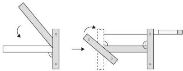
▶ Always fix the panel on two upper locks, two lower locks serve to a reverse suspension of the panel.
▶ Connect the lead-in cable to a fixed power distribution in accordance with the colour marking of the wires.
▶ Put the panel on the two upper locks.
See Fig. 9 at the end of the document.
Horizontal mounting
▶ Position the mounting frame in the location where the panel is to be placed.
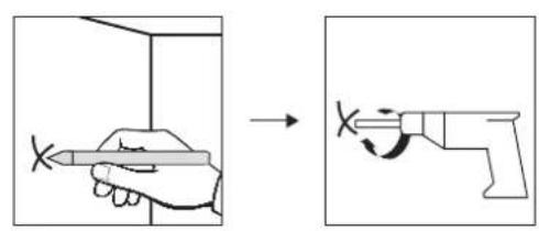
▶ Using a pen, mark the holes according to the holes on the frame.
- Drill the holes, insert the wall anchors and attach the mounting frame with the screws.
- Connect the lead-in cable to the mains in accordance with the colour of the conductors.
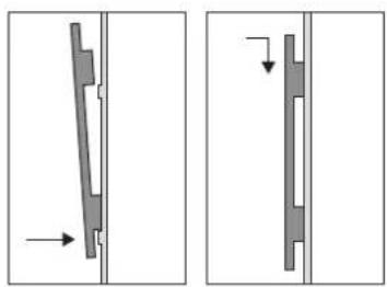
▶ Slide the panel into the mounting frame.
See Fig. 8 at the end of the document
Anchoring
It is forbidden to use wall anchors with a self-tapping thread to attach panels to plasterboard/gypsum fibreboard ceilings.
Make sure to use the right type of anchoring element (wall plug), particularly when dealing with plasterboard/gypsum fibreboard and porous concrete structures.
When installing radiant panels on plasterboard or gypsum-fiber ceilings, it is necessary to keep the distance between the panel and the ceiling of, at least, 70 mm.
Uninstalling the panel from the wall
▶ Disconnect the panel from the mains using a two-pole switch before uninstalling it.
▶ Lift the panel upwards vertically and sideways in such a way that it is released from the screws.
▶ Disconnect the supply cable from the box on the wall.
6 C I e a n i n g
Cleaning the panel
Always clean the whole surface of the glass or ceramic, not partially.
Cleaning must be performed while the glass is wet.
After the application of cleaning agent, use a soft, clean, non-fraying cotton cloth.
Do not apply any great pressure when carrying out the cleaning itself, as this could cause scratches or smudges to appear on the surface of the glass.
Wipe the glass in this way until the cleaning agent dries up evenly. The more even the wet surface is, the lower the risk of smudging.
Never use pressure to wipe the glass dry. If smudges appear on the glass anyway, please repeat the procedure.
The glass panel must be protected against aggressive substances such as lime, soda, cement, etc., and must not come into contact with any kind of paint or varnish.
i
All products containing hydrofluoric acids or fluoride derivatives are prohibited as they may damage the coating and surface of the glass.
Do not use abrasive or aggressive cleaning agents for any cleaning work. Always use pH-neutral cleaners, as strongly acidic or alkaline cleaners can attack the surface coatings.
The metal version with the structured surface can be cleaned with a soft brush.
| 7 T r o u b l e s h o o t i n g | ||
| Error Causes Remedy | ||
| The appliance heats continuously. The control unit is continuously exposed to draughts. | ► Close doors and windows. | |
| The selected appliance output does not match the size of the room. The infrared heater is sized too small. | ► Check whether the selected output is suitable for the size of the room (25W/m2for a average insulated room; well insulated room 6-18W/m2; good insulated room 18-24W/m2; averagely insulated room 24-32W/m2; badly insulated room 32W/m2). | |
| The surface of the panel is very hot. | The selected appliance output does not match the size of the room. | ► Check whether the selected output is suitable for the size of the room (25W/m2for a average insulated room; well insulated room 6-18W/m2; good insulated room 18-24W/m2; averagely insulated room 24-32W/m2; badly insulated room 32W/m2). |
Table 19 Faults, possible causes and remedies
8 Environmental protection and disposal
Environmental protection is a fundamental corporate strategy of the Bosch Group.
The quality of our products, their economy and environmental safety are all of equal importance to us and all environmental protection legislation and regulations are strictly observed.
We use the best possible technology and materials for protecting the environment taking account of economic considerations.
Packaging
Where packaging is concerned, we participate in country-specific recycling processes that ensure optimum recycling.
All of our packaging materials are environmentally compatible and can be recycled.
Used appliances
Used appliances contain valuable materials that can be recycled.
The various assemblies can be easily dismantled. Synthetic materials are marked accordingly. Assemblies can therefore be sorted by composition and passed on for recycling or disposal.
Old electrical and electronic appliances

This symbol means that the product must not be disposed of with other waste, and instead must be taken to the waste collection points for treatment, collection, recycling and disposal.
The symbol is valid in countries where waste electrical and
electronic equipment regulations apply, e.g. "(UK) Waste Electrical and Electronic Equipment Regulations 2013 (as amended)". These regulations define the framework for the return and recycling of old electronic appliances that apply in each country.
As electronic devices may contain hazardous substances, it needs to be recycled responsibly in order to minimize any potential harm to the environment and human health. Furthermore, recycling of electronic scrap helps preserve natural resources.
For additional information on the environmentally compatible disposal of old electrical and electronic appliances, please contact the relevant local authorities, your household waste disposal service or the retailer where you purchased the product.
You can find more information here:
www.weee.bosch-thermotechnology.com/
Batteries
Batteries must not be disposed together with your household waste.
Used batteries must be disposed of in local collection systems.
9 Data Protection Notice

We, Bosch Thermotechnology Ltd., Cotswold Way, Warndon, Worcester WR4 9SW, United Kingdom process product and installation information, technical and connection data, communication data, product registration and client history data to provide product functionality (art. 6 (1) sentence 1 (b) GDPR
/ UK GDPR), to fulfil our duty of product surveillance and for product safety and security reasons (art. 6 (1) sentence 1 (f) GDPR / UK GDPR), to safeguard our rights in connection with warranty and product registration questions (art. 6 (1) sentence 1 (f) GDPR / UK GDPR) and to analyze the distribution of our products and to provide individualized information and offers related to the product (art. 6 (1) sentence 1 (f) GDPR / UK GDPR). To provide services such as sales and marketing services, contract management, payment handling, programming, data hosting and hotline services we can commission and transfer data to external service providers and/or Bosch affiliated enterprises. In some cases, but only if appropriate data protection is ensured, personal data might be transferred to recipients located outside of the European Economic Area and the United Kingdom. Further information are provided on request. You can contact our Data Protection Officer under: Data Protection Officer, Information Security and Privacy (C/ISP), Robert Bosch GmbH, Postfach 30 02 20, 70442 Stuttgart, GERMANY.
You have the right to object, on grounds relating to your particular situation or where personal data are processed for direct marketing purposes, at any time to processing of your personal data which is based on art. 6 (1) sentence 1 (f) GDPR / UK GDPR. To exercise your rights, please contact us via privacy.ttgb@bosch.com To find further information, please follow the QR-Code.
10 Technical information and reports
10.1 Technical Data
| Infrared panel Unit | Glass | version | Ceramic version | Metallic version |
| Rated output of the panel | W 300W|500W|700W|850W | 300W|500W|700W | 300W|500W|700W|850W|1000W | |
| Operating voltage V 230 V AC 230 V AC 230 V AC | ||||
| Current A 1,3|2,2|3,0 | |3,7 | 1,3|2,2|3,0 | 1,3|2,2|3,0|3,7|4,4 | |
| IP rating/protection class | IP | 44/I | 44/I | 44/I |
| Connection cable | - | two-conductor cable for 1/N 230V/Hz | two-conductor cable for 1/N 230V/Hz | two-conductor cable for 1/N 230V/Hz |
| Weight | kg | 9|12|16|22 | 10|14|19 | 5,5|10|13|15|16 |
Table 20 Specifications for the panel
i
The panel can be installed on bases of flammability class A, B, C1 or C2.
10.2 Product data for energy consumption
The following product data satisfy the requirements of the EU Regulation No. 2015/1188.
| Product data | Symbol | Unit | Infrared panel |
| Heat output | |||
| Specified heat output | P_rated | kW | 0.3; 0.5; 0.7; 0.85; 1.0 |
| Minimum heat output (indicative) | P_min | KW | 0.0 |
| Maximum continuous output | P_max,c | KW 0.3; 0.5; 0.7; 0.85; 1.0 | |
| Auxiliary electricity consumption | |||
| For rated heat output | eI_max | KW | 0.000 |
| At minimum heat output | eI_min | KW | 0.000 |
| In standby mode | eI_sb | kW | 0.000 |
Table 21 Product data for energy consumption
i
For all informations regarding the control unit, please consult the manual of the controller.
| Type of heat output/room temperature control | |
| Yes/No | |
| single-level heat output, no room temperature control | Yes |
| two or more manually adjustable levels, no room temperature control | No |
| heat output/room temperature control with mechanical thermostat | No |
| with electronic room temperature control | No |
| electronic room temperature control and time-of-day control | No |
| Type of heat output/room temperature control | |
| electronic room temperature control and weekday control | No |
| Other control options | |
| room temperature control with presence detection | No |
| room temperature control with open window detection | No |
| with remote control option | No |
| with adaptive control of heating start | No |
| with operating time limitation | No |
| with black bulb sensor | No |
Table 22
11 Service addresses
EN: For all detailed product related information (technical specifications, detailed user/operation manual, installation instructions, etc.) and warranty card please scan the QR Code on the left side with your mobile device or visit: www.docs.bosch-thermotechnology.com/download/pdf/file/6721850726.
0010049042-001
5 Installation ....29
6 Nettoyage ....30
Documentation technique
i
5 Installation ....69
6 Rengöring ....70
7 Felsökning....70
1
natural_image
Simple diagram showing a rectangle and a horizontal bar with vertical supports (no text or symbols)2
3
4
5
6
natural_image
Mechanical diagram showing a lever mechanism with rotating and unrolled parts (no text or symbols)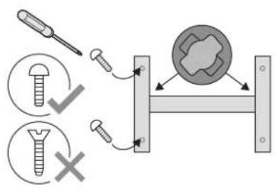
natural_image
Two mechanical component diagrams showing a left and right view with arrows indicating motion or force direction (no text or symbols)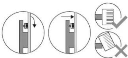
0010345125-001

www.docs.bosch-thermotechnology.com/download/pdf/file/6721850726