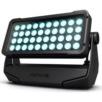
ZENIT W600i - Lighting Cameo - Free user manual and instructions
Find the device manual for free ZENIT W600i Cameo in PDF.


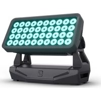
| Product type | LED wash projector for outdoor use |
| Brand | Cameo |
| Model | ZENIT W600i |
| LED | 40 high-power RGBW LEDs 15 W (SMD 4-in-1) |
| Beam angle | 18° (field 35°) |
| Protection rating | IP67 |
| Impact resistance rating | IK08 |
| Operating voltage | 100-240 V AC, 50-60 Hz |
| Power consumption | 565 W |
| Luminous flux (RGBW) | 21,000 lm |
| Illuminance at 1 m | 120,000 lx |
| Dimensions (W x H x D) | 449 x 291 x 161 mm |
| Weight | 13 kg |
| Housing material | Die-cast aluminum, powder coating C5-M, black |
| Cooling | 3 IP67 fans |
| DMX functions | DMX-512, RDM, 2 to 15 channel modes, 16-bit dimmer, strobe, 4 dimmer curves, color temperature correction |
| Standalone functions | Auto, Color Macro, Static, Tunable White, User Color, Timer, Master/Slave |
| LED PWM frequency | 800 Hz, 1200 Hz, 2000 Hz, 3600 Hz, 12 kHz, 25 kHz (adjustable) |
| Included accessories | Locking pin, 2 mounting omegas, 4 M8x25 screws with washers, 4 M4x18 screws |
| Optional accessories | External display module, mounting plate, protective diffusers, anti-glare shields |
| Maintenance | Regular cleaning of surfaces, ventilation openings and lenses; check fans every 500 h |
| Minimum distance (flammable materials / illuminated surface) | 0.5 m |
| Ambient operating temperature | -15 °C to +45 °C |
| Safety | Do not look into the beam, do not open the device, installation by qualified personnel |
Frequently Asked Questions - ZENIT W600i Cameo
User questions about ZENIT W600i Cameo
0 question about this device. Answer the ones you know or ask your own.
Ask a new question about this device
Download the instructions for your Lighting in PDF format for free! Find your manual ZENIT W600i - Cameo and take your electronic device back in hand. On this page are published all the documents necessary for the use of your device. ZENIT W600i by Cameo.
USER MANUAL ZENIT W600i Cameo
natural_image
Black and white photo of a modern LED array with 24 circular light bulbs (no text or symbols visible)ZENIT® W600i
OUTDOOR LED WASH LIGHT FOR FIXED INSTALLATION
CLZW600i
CONTENTS / INHALTSVERZEICHNIS / TABLE DES MATIÈRES / CONTENIDO / SPIS TREŚCI / CONTENUTO
ENGLISH
INFORMATION ON THIS USER MANUAL 6
INTENDED USE 6
DEFINITIONS AND SYMBOL EXPLANATIONS 6
SAFETY INSTRUCTIONS 7
INSTRUCTIONS FOR INSTALLATION EQUIPMENT 10
FEATURES 11
CONNECTIONS, OPERATING AND DISPLAY ELEMENTS 11
SIGNAL AND POWER CABLE 13
OPERATION 15
ADJUSTING LIGHT HEAD TILT 23
INSTALLATION AND TRUSS MOUNTNG 24
INSTALLATION OF OPTIONAL ACCESSORIES 25
INSTALL SPOTLIGHT WITH OPTIONAL MOUNTING PLATE 26
CARE, MAINTENANCE AND REPAIR 27
OPTIONAL ACCESSORIES 29
TECHNICAL DATA 30
EXPLANATION OF IP PROTECTION CLASS 32
EXPLANATORY NOTES ON IK IMPACT RESISTANCE RATING 33
MINIMUM DISTANCE TO ILLUMINATED SURFACE 33
MINIMUM DISTANCE TO NORMALLY FLAMMABLE MATERIALS 33
DISPOSAL 34
MANUFACTURER'S DECLARATIONS 34
DEUTSCH
PRZEWÓD SYGNAŁOWY I SIECIOWY 136
OBSŁUGA 138
REGULACJA ODCHYLENIA ŚWIATŁA 147
USTAWIANIE I MONTAŻ NA KRATOWNICY 148
MONTAŻ OPCJONALNYCH AKCESORIÓW 149
INSTALACJA REFLEKTORA PRZY UŻYCIU OPCJONALNEJ PŁYTY MONTAŻOWEJ 151
CZYSZCZENIE, KONSERWACJA I NAPRAWY 152
AKCESORIA DODATKOWE 154
DANE TECHNICZNE 155
OBJAŚNIENIA DOTYCZĄCE STOPNIA OCHRONY IP 157
UWAGI DOTYCZĄCE POŻIOMU ODPORNOŚCI NA WSTRZĄSY IK 158
MINIMALNA ODŁEGŁOŚĆ OD POWIERZCHNI OŚWIETLONEJ 158
MINIMALNA ODLEGŁOŚĆ OD NORMALNIE ŁATWOPALNYCH MATERIAŁÓW 158
UTYLIZACJA 159
DEKLARACJE PRODUCENTA 159
ITALIANO
INFORMAZIONI SUL PRESENTE MANUALE D'USO 160
UTILIZZO CONFORME 160
SPIEGAZIONE DI CONCETTI E SIMBOLI 160
This device has been developed and manufactured to the highest quality standards to ensure many years of problem-free operation. Please read this manual carefully to be able to use your new Cameo product quickly and optimally. Further information about Cameo Light is available on our website CAMEOLIGHT.com.
INFORMATION ON THIS USER MANUAL
- Carefully read the safety instructions and the entire manual before operating the device.
- Observe the warnings on the device and in the user manual.
- Always keep the user manual within reach.
- If you sell or pass on the device, it is important that you also include this user manual, as it is an integral part of the product.
INTENDED USE
This product is an outdoor spotlight for permanent installation! This spotlight is intended exclusively for professional users and is not suitable for private households or third parties! Use of the product outside the specified technical data and operating conditions, as well as incorrect installation, is considered inappropriate! Liability for damage and third-party damage to persons and property due to inappropriate use is excluded!
The product is not suitable for:
- Use by persons (including children) with limited physical, sensory or mental abilities or lack of experience and knowledge.
- Children (children must be instructed not to play with the device).
DEFINITIONS AND SYMBOL EXPLANATIONS
- HAZARD: The word HAZARD, possibly in combination with a symbol, indicates situations in which there is an immediate danger or risk of potentially fatal injury.
- WARNING: The word WARNING, possibly in combination with a symbol, indicates situations in which there is an immediate danger or risk of potentially fatal injury.
- CAUTION: The word CAUTION, possibly in combination with a symbol, indicates situations or conditions that could result in injury.
- ATTENTION: The word ATTENTION, possibly in combination with a symbol, indicates situations or states that may lead to property damage and/or environmental damage
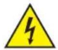
This symbol identifies hazards that can cause electric shock.

This symbol identifies hazardous areas or hazardous situations.

This symbol indicates hazards caused by hot surfaces.
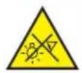
This symbol indicates hazards caused by intense light sources.

This symbol indicates a device in which there are no user-replaceable parts.

This symbol indicates additional information on the operation of the product.
SAFETY INSTRUCTIONS
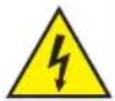
HAZARD:
- Do not open the device and do not perform any modifications.
- If your device no longer functions properly, if liquids or objects get inside it or if it has been damaged in any other way, switch it off immediately and unplug it from the power source. The device may be repaired only by authorised repair technicians.
- For devices of protection class 1, the protective conductor must be connected correctly. Never disconnect the protective conductor. Devices of protection class 2 do not have a protective conductor.
- Ensure that live cables are not kinked or otherwise mechanically damaged.
- Never bypass the device fuse.
WARNING:
- The device may not be operated if it shows obvious signs of damage.
- The device may only be installed in a voltage-free state.
- If the device's power cable is damaged, the device may not be used.
- Permanently connected power cables may only be replaced by a qualified person.
CAUTION:
- Do not switch on the device if it has been exposed to extreme temperature fluctuations (for example, following transport). Moisture and condensation can damage the device. Switch on the device only when it has reached room temperature.
- Ensure that the voltage and frequency of the mains supply match the values specified on the device. If the device has a voltage selector switch, do not connect the device until it has been set correctly. Use only suitable power cables.
- To disconnect the device from the mains on all poles, it is not sufficient to press the on/off switch on the device.
- Make sure that the fuse used corresponds to the type printed on the device.
- Ensure that suitable measures have been taken against overvoltage (e.g. lightning strikes).
- Observe the specified maximum output current on devices with a Power Out connection. Ensure that the total current consumption of all connected devices does not exceed the specified value.
- Replace pluggable power cables with original cables only.

HAZARD:
- Choking hazard! Plastic bags and small parts must be kept out of reach of persons (including children) with reduced physical, sensory or mental capabilities.
- Risk of falling! Make sure that the device is securely installed and will not fall down. Only use suitable stands or mountings (particularly for fixed installations). Ensure that accessories are properly installed and secured. Ensure that applicable safety regulations are observed.

WARNING:
- Use the device in the prescribed manner only.
- Operate the device using only accessories of the type recommended and supplied by the manufacturer.
- Observe safety regulations applicable in your country during installation.
- After connecting the device, ensure that all cables are routed so as to avoid damage or accidents, such as from tripping.
- Always observe the specified minimum distance to normally flammable materials! Unless explicitly stated, the minimum distance is 0.3 m.
- Always observe the minimum distance to the illuminated surface that can be read on the device!

CAUTION:
- Moving components such as mounting brackets may become jammed.
- In the case of devices with motor-driven components, there is a risk of injury due to the movement of the device. Sudden movement of the device can cause shock reactions.
- The housing surface of the device can become very hot during regular operation. Ensure that accidental touching of the housing is not possible. Always allow the lamp to cool sufficiently before removal, maintenance work and charging etc.

CAUTION:
- Do not install or use the device in the vicinity of radiators, accumulators, stoves, or other heat sources Ensure that the device is always installed in such a way that it is sufficiently cooled and cannot overheat.
- Do not place any ignition sources, such as burning candles, near the device.
- Ventilation openings may not be covered and fans may not be blocked.
- For transport, use the original packaging or packaging provided by the manufacturer.
- Avoid any impacts to or shaking of the device.
- Observe the IP rating and the ambient conditions such as temperature and humidity according to the specification.
- Devices can be continuously further developed. In the event of deviating information on operating conditions, performance or other device properties between the user manual and the device labelling, the information on the device always has priority.
- The device is not suitable for tropical climate zones or for operation over 2,000 m above sea level.
- Unless explicitly stated, the device is not suitable for operation under marine conditions.
CAUTION! IMPORTANT INFORMATION REGARDING LIGHTING PRODUCTS!

- Never look directly into the beam of light, not even for a short period of time.
- Never look into the beam of light using optical devices such as a magnifying glass.

- Stroboscopic effects may cause epileptic seizures in those susceptible!

- A permanently installed lamp is installed in this lighting unit which must not be replaced by the user. In the event of a fault, please contact your sales partner.
INSTRUCTIONS FOR INSTALLATION EQUIPMENT
- Equipment for installation applications is designed for continuous operation.
- Equipment for outdoor installation is largely weather-resistant. Depending on the design, however, installed seals may be made of materials that deteriorate over time. These must be checked regularly and replaced if necessary.
- The correct condition of the housing parts and connections must be checked regularly.
- Surfaces and plastic parts can also weather in installation equipment, e.g. due to UV irradiation. This generally does not impair functionality.
- Damage to the surface coating can impair the device's corrosion protection. Damaged surface coating (e.g. scratches) must be promptly repaired by suitable measures.
- Screw connections can be impaired in their freedom of movement (e.g. due to oxidation or impurities). Here, appropriate measures for loosening are to be implemented.
- Unless explicitly stated otherwise on the device or in the technical data, the devices are intended for installation heights of less than 5 m.
NOTES FOR INSTALLATION DEVICES
- units for installation applications are designed for continuous operation.
- units for outdoor installation are largely weatherproof. However, depending on the design, seals made of ageing materials are installed. These must be checked regularly and replaced if necessary.
- The correct condition of the housing parts and connections must be checked regularly.
- Surfaces and plastic parts of installation units can also weather, e.g. due to UV radiation. This does not usually lead to functional restrictions.
- Damage to the surface coating can impair the corrosion protection of the unit. A damaged surface coating (e.g. scratches) must be restored promptly by suitable measures.
- The freedom of movement of screw connections can be impaired (e.g. by oxidation or contamination). If necessary, appropriate measures must be taken to loosen them.
- Unless explicitly stated otherwise on the unit or in the technical data, the units are intended for installation heights of less than 5 m.
FEATURES
IP67 protection rating. Impact resistance rating IK08. 40 x 15 W high-power RGBW LEDs.
DMX-512. Strobe. 16-bit dimmer. 4 dimmer curves. Colour temperature correction. Adjustable
LED PWM frequency. Fast Access Feature. Plastic feet. 2 x Omega mounting brackets included.
Operating voltage 100–240 V AC. Power consumption 565 W. Diffusers, glare shield and mounting plate optionally available.
The spotlight features the RDM standard (Remote Device Management). Remote device management allows the user to view the status and configuration of RDM terminals via an RDM-capable controller.
CONTROL FUNCTIONS
2-channel CCT, 3-channel colour macros, 3-channel RGB 8-bit, 4-channel RGBW 8-bit, 6-channel
RGB 16-bit, 8-channel RGBW 8-bit, 8-channel RGBW 16-bit, 10-channel full access 8-bit and 15-channel full access 16-bit DMX control
Master/slave operation
Standalone functions
DELIVERY CONDITION
15-channel full access DMX mode, DMX start address 001
CONNECTIONS, OPERATING AND DISPLAY ELEMENTS

1 DMX
Cable gland with a fixed 5-pin signal cable for DMX input and output.
2 CONNECTION FOR DISPLAY MODULE
Connection socket for an external module with display and touch-sensitive controls (optional). The socket has a cover cap with seal. Ensure that the socket is securely closed with the cover cap when the module is not connected.
3 POWER
Cable gland with a fixed power cable for power supply.
natural_image
Line drawing of a device with a connector and cable, no text or symbols present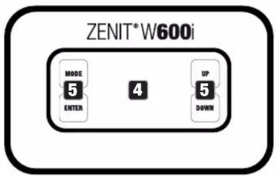
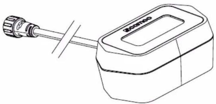
DISPLAY MODULE
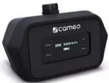
A special external module with display and touch-sensitive controls is optionally available for configuring the spotlight (product number CLZIEXDISP). The module is connected to the spotlight using a special connecting cable. Ensure that the connections are tightly sealed and that moisture cannot penetrate into the spotlight housing and the housing of the display module. Once the spotlight configuration is complete, the module must be disconnected from the spotlight again and the connection on the spotlight must be securely sealed using the cover cap. The module can now be used to configure additional spotlights.
4 OLED DISPLAY
The OLED display shows the currently activated mode (main display), the menu items in the selection menu and the numerical value or operational status in certain menu items.
5 TOUCH-SENSITIVE CONTROLS
MODE
Press MODE to access the main menu. Press repeatedly to return to the main display.
ENTER
Press ENTER to access the menu levels to make value changes, and to access the sub-menus. Confirm value changes by pressing ENTER.
UP and DOWN
Select individual menu items in the selection menu (DMX address, operating mode etc.) and in the sub-menus. Allow changes to be made to a menu item setting such as the DMX address as required.
PRESSURE EQUALISATION ELEMENT
The pressure equalisation element to prevent condensation forming inside the housing is located in the base of the device. In order to ensure its proper function, the element must be protected from contamination by regular cleaning.
HOUSING FAN
The three IP67-rated housing fans and heat sink are located on the rear of the LED unit. To ensure air circulation,
do not cover the device and clean it regularly.
SIGNAL AND POWER CABLE
There are no plugs or sockets at the cable ends of the DMX signal cable and the cable for the spotlight's power supply. Therefore, the spotlight may only be wired by trained specialist personnel. Extensive knowledge of handling data and power cables, as well as the creation of waterproof connections and junctions according to protection class IP67, is required.
If you do not have these qualifications, do not attempt to install cables yourself. Refer instead to a qualified professional. Liability is excluded for damage resulting from improper handling in all work steps necessary for safe operation. Ensure that no mains voltage is present in cables and spotlights during all work steps that are necessary for cabling.
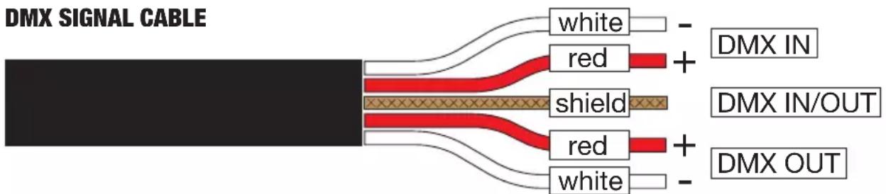
DMX input and output
| white DMX IN minus (-) | ||
| red DMX IN plus (+) | ||
| shield DMX IN/OUT | ||
| red DMX OUT plus (+) | ||
| white DMX OUT minus (-) |
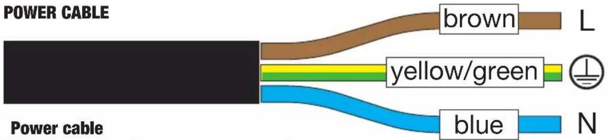
| brown Phase (L) | |
| yellow/green Grounding conductor | |
| blue Neutral (N) | |
PLEASE NOTE
No display module connected to the spotlight:
- When the spotlight is supplied with mains voltage, the start-up process begins. During the start-up process, the previously selected operating mode is activated and the spotlight is operational after a short time.
Display module connected to the spotlight:
- When the spotlight is supplied with mains voltage, the start-up process begins and the following are displayed in succession: "Welcome to Cameo", the model name and the software version. During the start-up process, the previously selected operating mode is activated and the spotlight is operational after a short time.
- Before changing device settings, ensure that the control panel is dry and free of dust in order not to impair its functionality.
- If one of the DMX operating modes is activated and there is no DMX signal to the DMX input, the currently programmed DMX address is displayed and the characters on the display will begin to flash.
- The main display is activated automatically if there is no input for a period of approximately one minute.
Fast Access Feature: In order to simplify the menu guide, the device has an intelligent menu structure that allows direct access to previously selected menu items and submenu items.
- Press MODE and ENTER simultaneously for direct access to the last-edited submenu item, where you can make changes instantly as required (DMX starting address and all modes).
-
Press MODE to go directly to the last selected and edited menu item. If you now repeatedly press ENTER, you can access the submenu items to make individual settings (DMX start address and all operating modes).
-
The display can be rotated through 180^ by pressing UP when the main display is visible.
- To quickly change a value (e.g. DMX start address), press and hold the UP or DOWN controls.
OPERATION
MAIN DISPLAY
The main display shows the currently activated operating mode (in the example: DMX operating mode with start address 001).
DMX Address
001
CONFIGURING DMX START ADDRESS (DMX Address)
Press MODE to access the main menu (--- Menu ---). Using the UP and DOWN controls, select the menu item DMX address (observe arrow) and confirm with ENTER. The display will show a three-digit number field and you can use the UP and DOWN controls to configure the desired DMX start address. Confirm the entry with ENTER and press MODE to return to the main display (in the example, "DMX address 001").
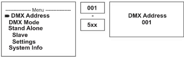
CONFIGURING DMX MODE (DMX Mode)
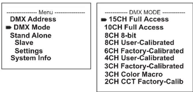
Press MODE to access the main menu (--- Menu ---). Using the UP and DOWN controls, select the menu item DMX Mode (observe arrow) and confirm with ENTER. In the submenu, you can now select from the different DMX modes with UP and DOWN. Confirm your selection with ENTER. Tables with the channel assignments can be found in these instructions under DMX CONTROL.
CONFIGURE STANDALONE MODE
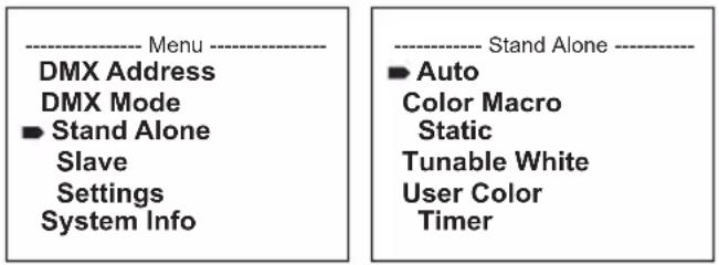
Press MODE to access the main menu (--- Menu ---). Use UP and DOWN to select the menu item Stand Alone (observe arrow) and confirm with ENTER. In the sub-menu you can now select from the standalone modes Auto, Color Macro, Static, Tunable White, und User Color and the timer feature Timer with the UP and DOWN controls. Confirm your selection with ENTER.
AUTO MODE (Program 1 to Program 6)
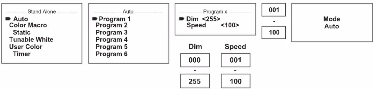
The 6 different auto-programs each comprise non-editable colour-change sequences. Brightness and speed are independently adjustable. Select auto mode as described above under "CONFIGURE STANDALONE MODE" and confirm with ENTER. Now use UP and DOWN to select one of the 6 auto programs (observe arrow) and confirm with ENTER. To adjust brightness, use UP and DOWN to select the menu item Dim and confirm with ENTER, then use UP and DOWN to select the desired value between 000 and 255. Confirm with ENTER. Set the run speed by selecting the menu item Speed, confirm with ENTER, and then select the desired value between 001 and 100. Confirm with ENTER. Press MODE four times to return to the main display (Mode Auto).
flowchart
graph TD
    A["Stand Alone"] --> B["Auto"]
    B --> C["Program 1"]
    B --> D["Program 2"]
    B --> E["Program 3"]
    B --> F["Program 4"]
    B --> G["Program 5"]
    B --> H["Program 6"]
    I["Program x"] --> J["Dim <255> Speed <100>"]
    K["Mode Auto"] --> L["001"]
    K --> M["-"]
    K --> N["100"]
    O["Dim"] --> P["000"]
    O --> Q["255"]
    P --> R["Speed"]
    Q --> S["Speed"]
    T["100"] --> U["Mode Auto"]
COLOUR MACROS (Color Macro)
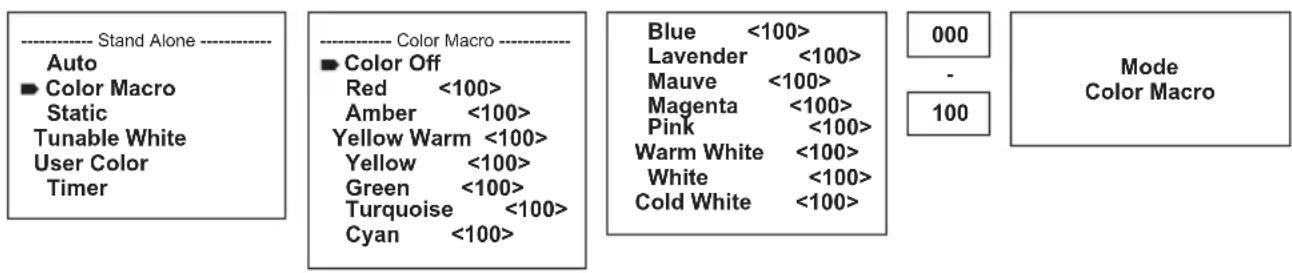
15 different preset colour macros are available. Select Color Macro as described above under CONFIGURE STANDALONE MODE and confirm with ENTER. Using the UP and DOWN controls, now select the desired colour preset (observe arrow) and confirm with ENTER (Colour Off = blackout). A three-digit figure is shown on the display, and you can set the desired brightness on a scale from 000 to 100 using UP and DOWN. Confirm with ENTER. Press MODE three times to return to the main display (Color Macro Mode).
flowchart
graph LR
    A["Stand Alone"] --> B["Auto"]
    B --> C["Color Macro"]
    C --> D["Static"]
    D --> E["Tunable White"]
    E --> F["User Color"]
    F --> G["Timer"]

    H["Color Macro"] --> I["Color Off"]
    I --> J["Red <100>"]
    I --> K["Amber <100>"]
    I --> L["Yellow Warm <100>"]
    I --> M["Yellow <100>"]
    I --> N["Green <100>"]
    I --> O["Turquoise <100>"]
    I --> P["Cyan <100>"]

    Q["Mode Macro"] --> R["Blue <100>"]
    Q --> S["Lavender <100>"]
    Q --> T["Mauve <100>"]
    Q --> U["Magenta <100>"]
    Q --> V["Pink <100>"]
    Q --> W["Warm White <100>"]
    Q --> X["White <100>"]
    Q --> Y["Cold White <100>"]

    Z["Mode Macro"] --> AA["000"]
    Z --> AB["-"]
    Z --> AC["100"]
STATIC MODE (Static)
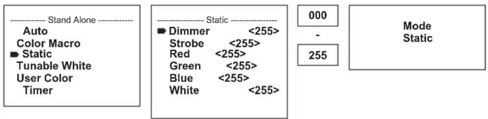
Static mode allows the functions Dimmer, Strobe and R, G, B, W to be adjusted directly on the device with values between 000 and 255, in a similar way to with a DMX controller. In this way, an individual scene can be created without an additional DMX controller. Select the static mode as per the procedure previously described in SETTING STAND ALONE MODE and confirm with ENTER. Now use UP and DOWN to select the menu item you wish to edit (observe arrow) and confirm with ENTER. The display will now show a three-digit number field, and you can use UP and DOWN to configure the desired value between 000 and 255. Confirm with ENTER. Press MODE three times to return to the main display (Static Mode).
COLOUR TEMPERATURE (Tunable White)
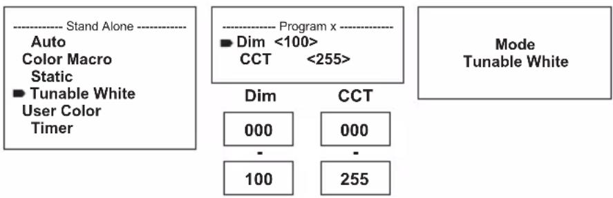
The colour temperature mode enables you to configure the colour temperature from cold white to warm white (CCT) and the brightness (Dim) of the light directly on the device. Select the colour temperature mode as per the procedure previously described in SETTING STAND ALONE MODE and confirm with ENTER. Now use UP and DOWN to select the menu item you wish to edit (observe arrow) and confirm with ENTER. The display will now show a three-digit number field and you can use UP and DOWN to configure the desired value. Confirm with ENTER. Press MODE three times to return to the main display (Mode Tunable White).
flowchart
graph TD
    A["Stand Alone"] --> B["Auto Color Macro Static"]
    B --> C["Tunable White User Color Timer"]
    D["Program x"] --> E["Dim <100> CCT <255>"]
    E --> F["Dim 000"]
    E --> G["CCT 000"]
    E --> H["-"]
    E --> I["100"]
    E --> J["255"]
    K["Mode Tunable White"]
USER PRESETS (User Color)
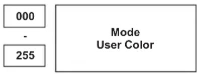
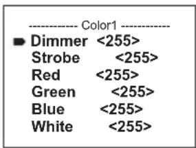
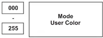
The operating mode "User Presets" allows the overall brightness and a colour mixture of R, G, B and W to be saved directly in the device in five individual colour presets. Select the User Color mode as per the procedure previously described in SETTING STAND ALONE MODE and confirm with ENTER. Use UP AND DOWN to select one of the stored presets Color1 to Color5 and confirm with ENTER and select the submenu item you want to edit (see arrows). Confirm with ENTER. The display will show a three-digit number field and you can use the UP and DOWN controls to set the value as required between 000 and 255. Confirm by pressing ENTER again. When all settings are configured as required, press MODE four times to return to the main display (Mode User Colour).

TIMER FUNCTION (Timer)
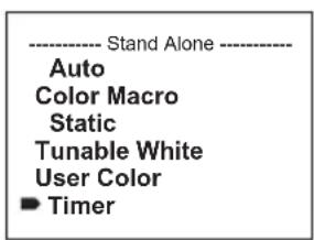
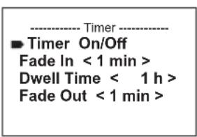
The timer function allows the standalone modes “Colour Macro”, “Static”, “Tunable White” and “User Colour” to be timer controlled in such a way that the fade-in time can be set from 0 to 60 minutes, the dwell time from 1 to 24 hours and the fade-out time from 0 to 60 minutes. Time control starts immediately after activating the timer function in the previously activated standalone mode and remains active even if the spotlight is switched off and restarted. Select Timer as per the procedure described above under CONFIGURE STANDALONE MODE and confirm with ENTER. Now select “Fade In”, “Dwell Time” or “Fade Out” for the individual settings (observe arrow) and confirm with ENTER. The display will show a three-digit number field in each case. Use UP and DOWN to set the value as required from 000 to 060 or 001 to 024. Confirm by pressing ENTER again. Once all settings have been configured as required, activate the timer function by selecting the submenu item “Timer On/Off” using UP and DOWN, confirm with ENTER, select “On” and confirm again with ENTER (to deactivate the timer function, please select “Off” and confirm). Press MODE three times to return to the main display.
Please note: The timer function is suitable for use in master/slave mode via cable.
Press MODE to access the main menu (--- Menu ---). Using UP and DOWN, select the menu item Slave (observe arrow) and confirm with ENTER. Connect the slave and the master units (same model, same software version) with a DMX cable and enable one of the standalone modes on the master unit (Auto, Color Macro, Static, Tunable White, User Color). The slave unit will now follow the master unit. If there is no control signal, the display characters will flash. Flashing stops as soon as a control signal is present.
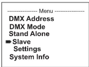
DEVICE SETTINGS (Settings)
Press MODE to access the main menu (--- Menu ---). Using the UP and DOWN controls, select the menu item Settings (observe arrow) and confirm with ENTER.
Menu
DMX Address
DMX Mode
Stand Alone
Slave
Settings
System Info
This will take you to the submenu for setting the following submenu items (see table, select with UP and DOWN, confirm with ENTER, change value or status with UP and DOWN, confirm with ENTER):
| Settings (device settings) | ||||
| Display Backlight | = | Display lighting On Permanently on | ||
| Off Deactivation after approximately 1 minute of inactivity | ||||
| DMX Fail | = | Operating status with DMX signal fault | Hold Last command is retained | |
| Blackout Activates blackout | ||||
| Emergency Light | Spotlight changes to colour macro "Cold White" | |||
| Dimmer Curve | = | Dimmer curve Linear Light intensity increase linearly with DMX value | ||
| Dimmer Response | = | Dimmer response LED | Lamp responds abruptly to changes in DMX value | |
| Halogen | Spotlight behaves like a halogen spot-light with soft brightness changes | |||
| Color Calibration | = | Colour calibration (If one of the factory-calibrated DMX modes is activated, no other calibration can be selected and “no possible change in this DMX Mode” is shown on the display. If one of the DMX modes with user calibration is activated, RAW can be selected as an alternative calibration) | RAW R, G, B | and W with maximum value 255 |
| User Calibration | Individual adaptation of R, G, B, and W with values of 000 to 255 each (across all modes) | |||
| Factory Calibration | Factory calibration of R, G, B and W (across all modes). Select this setting for uniform display of the colour macros in standalone mode, as well as for control of the colour macros via DMX. | |||
| Autolock | = | Automatic locking of the controls | On Automatic | locking of the controls after approximately 1 minute of inactivity. Display shown upon attempted use: “Locked!” Unlock: Press and hold UP and DOWN simultaneously for approx. 5 seconds |
| Off Automatic | locking of the controls is disabled | |||
| LED Frequency | = | LED PWM frequency 800 Hz/1200 Hz/2000 Hz/3600 Hz/12 kHz / 25 kHz | Hz/1200 Hz/2000 Hz/3600 Hz/12 kHz / 25 kHz | Configuration of LED PWM frequency |
| Fan | = | Adjust fan control Auto Automatic adjustment of the fan performance | ||
| Factory Reset | = | Reset to factory settings | Reset to factory settings: ENTER ->“Reset Now!” -> ENTER | |
Dimmer curves
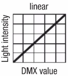
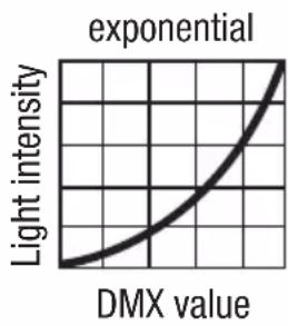
line
| DMX value | Light intensity | | --------- | --------------- | | 0 | 0 | | 1 | 0.5 | | 2 | 1 | | 3 | 2 | | 4 | 3 | | 5 | 4 | | 6 | 5 | | 7 | 6 | | 8 | 7 | | 9 | 8 | | 10 | 9 | | 11 | 10 | | 12 | 11 | | 13 | 12 | | 14 | 13 | | 15 | 14 | | 16 | 15 | | 17 | 16 | | 18 | 17 | | 19 | 18 | | 20 | 19 | | 21 | 20 | | 22 | 21 | | 23 | 22 | | 24 | 23 | | 25 | 24 | | 26 | 25 | | 27 | 26 | | 28 | 27 | | 29 | 28 | | 30 | 29 | | 31 | 30 | | 32 | 31 | | 33 | 32 | | 34 | 33 | | 35 | 34 | | 36 | 35 | | 37 | 36 | | 38 | 37 | | 39 | 38 | | 40 | 39 | | 41 | 40 | | 42 | 41 | | 43 | 42 | | 44 | 43 | | 45 | 44 | | 46 | 45 | | 47 | 46 | | 48 | 47 | | 49 | 48 | | 50 | 49 | | 51 | 50 | | 52 | 51 | | 53 | 52 | | 54 | 53 | | 55 | 54 | | 56 | 55 | | 57 | 56 | | 58 | 57 | | 59 | 58 | | 60 | 59 | | 61 | 60 | | 62 | 61 | | 63 | 62 | | 64 | 63 | | 65 | 64 | | 66 | 65 | | 67 | 66 | | 68 | 67 | | 69 | 68 | | 70 | 69 | | 71 | 70 | | 72 | 71 | | 73 | 72 | | 74 | 73 | | 75 | 74 | | 76 | 75 | | 77 | 76 | | 78 | 77 | | 79 | 78 | | 80 | 79 | | 81 | 80 | | 82 | 81 | | 83 | 82 | | 84 | 83 | | 85 | 84 | | 86 | 85 | | 87 | 86 | | 88 | 87 | | 89 | 88 | | 90 | 89 | | 91 | 90 | | 92 | 91 | | 93 | 92 | | 94 | 93 | | 95 | 94 | | 96 | 95 | | 97 | 96 | | 98 | 97 | | 99 | 98 | | Note: The actual values for light intensity are not provided in the code. The code does not provide a way to estimate the values from the original data source. I have used the label 'exponential' to indicate the magnitude of the exponential distribution. There is only one data series labeled 'DMX value'.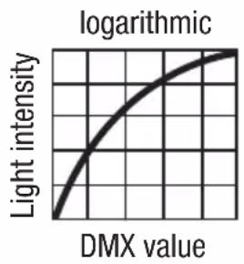
line
| DMX value | Light intensity | | --------- | --------------- | | 0 | 0 | | 1 | 0.5 | | 2 | 1 | | 3 | 1.5 | | 4 | 2 | | 5 | 2.5 | | 6 | 3 | | 7 | 3.5 | | 8 | 4 | | 9 | 4.5 | | 10 | 5 | | 11 | 5.5 | | 12 | 6 | | 13 | 6.5 | | 14 | 7 | | 15 | 7.5 | | 16 | 8 | | 17 | 8.5 | | 18 | 9 | | 19 | 9.5 | | 20 | 10 |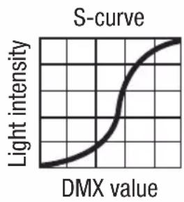
line
| DMX value | Light intensity | | --------- | --------------- | | 0 | 0 | | 1 | 0.5 | | 2 | 1 | | 3 | 1.5 | | 4 | 2 | | 5 | 2.5 | | 6 | 3 | | 7 | 3.5 | | 8 | 4 | | 9 | 4.5 | | 10 | 5 | | 11 | 5.5 | | 12 | 6 | | 13 | 6.5 | | 14 | 7 | | 15 | 7.5 | | 16 | 8 | | 17 | 8.5 | | 18 | 9 | | 19 | 9.5 | | 20 | 10 |SYSTEM INFORMATION (System Info)
Press MODE to access the main menu (--- Menu ---). Using the UP and DOWN controls, select System Info(observe arrow) and confirm with ENTER.
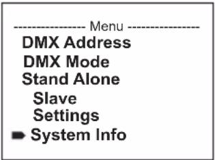
Use the UP and DOWN controls to select the desired submenu item, and press ENTER to display the corresponding information.
| System Info | ||||
| Firmware = Displays device firmware | Main CPU | Vx.xx | ||
| LEDDriver | Vx.xx | |||
| Temperature = Displays temperature of LED unit | LED xx °C | / xx °F | ||
| Unit °C (= | display in degrees Celsius) | |||
| °F (= display in degrees Fahrenheit) | ||||
| Operation Hours | = Displays operating time xx:xx h | Displays total operating time in hours and minutes | ||
MANUAL LOCKING FUNCTION
In addition to the ability to automatically protect the lamp from accidental and unauthorised operation (see "Settings" - "Auto-lock"), the controls can also be locked manually. Press and hold the UP and DOWN controls simultaneously for approximately 5 seconds. If an attempt is made to change settings, "Locked!" will appear in the display, and changing the spotlight's settings via the controls is no longer possible. After approx. 1 minute, the current operating mode is displayed again. To unlock, press and hold the UP and DOWN controls simultaneously for approximately 5 seconds. The display will show the previously displayed information.
ADJUSTING LIGHT HEAD TILT
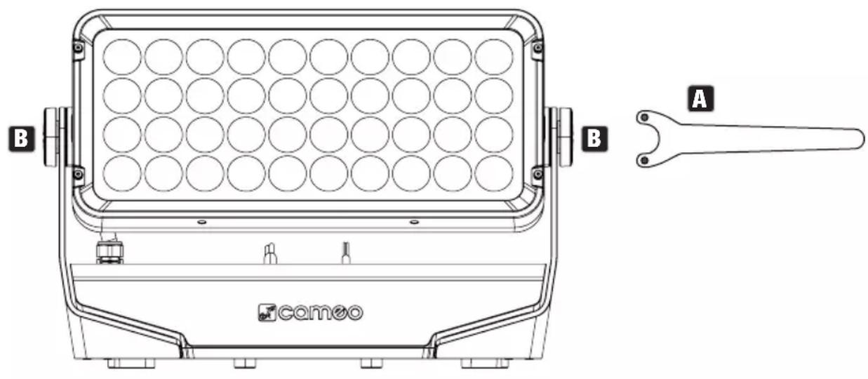
The light head tilt is adjusted using the supplied face spanner (A). Loosen the two-hole screws on both sides of the retaining bracket (B) only so far that the light head moves freely, adjust to the desired light head tilt and re-tighten the two-hole screws. Be careful not to over-tighten the two-hole screws.
INSTALLATION AND TRUSS MOUNTING
Thanks to its integrated plastic feet, the lamp can be positioned in a suitable location on a level surface. Installation on a truss is carried out with the help of two Omega brackets, which are mounted on the underside of the device base with a suitable tool (A). 2 x Omega brackets, 4 x M8 socket screws and washers are included. Suitable truss clamps are optionally available. Ensure firm connections and secure the spotlight to the intended position (B) with a suitable safety cable if required.

HAZARD: Overhead mounting requires extensive experience, including the calculation of the load limit values of the installation material and regular safety inspection of all installation materials and spotlights. If you do not have these qualifications, do not attempt to perform an installation yourself. Refer instead to a qualified professional. There is a risk that devices that are incorrectly mounted and secured may come loose and fall down. This can cause serious injury or death.
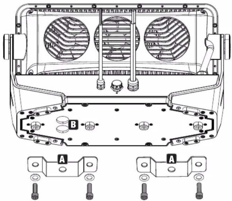
INSTALLATION OF OPTIONAL ACCESSORIES
DIFFUSER AND GLARE SHIELD
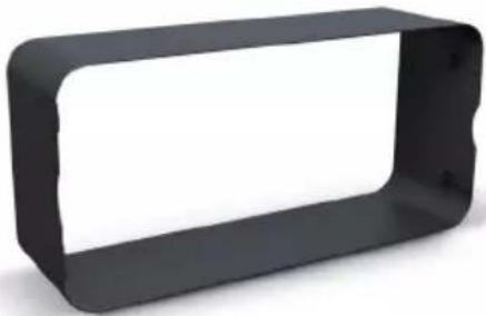
To mount accessories such as the diffuser and glare shield, loosen the 4 socket screws (see markings) using a suitable tool. Install the desired glare shield and, if required, a diffuser in the frame of the glare shield, then screw both to the spotlight using the previously loosened screws. The protection against foreign bodies and water, in accordance with protection class IP67, remains unchanged. Diffusers and glare shields in a range of designs are optionally available (see OPTIONAL ACCESSORIES).
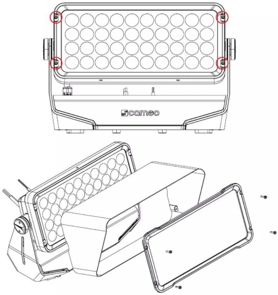
MOUNTING PLATE
Position the mounting plate on the underside of the spotlight base so that the holes in the base plate and the corresponding screw threads in the base are precisely aligned. Now fix the mounting plate to the base using the 4 supplied M4 screws and then secure the mounting plate to the spotlight base using the 4 M8 socket screws supplied with the spotlight.
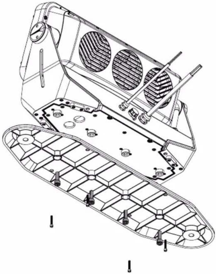
natural_image
Technical line drawing of a mechanical assembly with internal components and mounting holes (no text or symbols)INSTALL SPOTLIGHT WITH OPTIONAL MOUNTING PLATE
When attaching the spotlight to a surface, make sure that the surface is suitable for this purpose and provides sufficient support. Ensure that the installation materials, such as screws and plugs, etc., are suitable for mounting the spotlight and the surface material. Ensure that all screw connections are firmly secured.

HAZARD: Overhead mounting requires extensive experience, including the calculation of the load limit values of the installation material and regular safety inspection of all installation materials and spotlights. If you do not have these qualifications, do not attempt to perform an installation yourself. Refer instead to a qualified professional. There is a risk that devices that are incorrectly mounted and secured may come loose and fall down. This can cause serious injury or death.
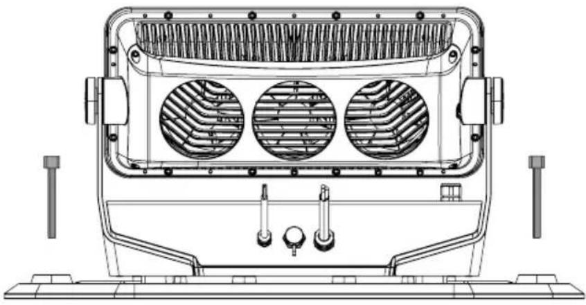
natural_image
Technical line drawing of a front-mounted industrial fan or heat exchanger unit with three circular vented chambers (no text or symbols)CARE, MAINTENANCE AND REPAIR
In order to ensure the long-term, proper functioning of the device, it must be regularly cleaned and, if necessary, maintained. The maintenance requirement depends on the intensity of use and the environment in which it is used. We generally recommend a visual inspection before each operation. Furthermore, we recommend carrying out all the applicable maintenance measures specified below once every 500 operating hours or, in the case of a lower intensity of use, at the latest after one year. Warranty claims may be limited in the event of defects resulting from inadequate maintenance.
CARE (carried out by user)
WARNING! Before carrying out any care or maintenance, the power supply – and, if possible, all device connections – must be disconnected.

PLEASE NOTE! Improper care can lead to impairment of the device or even its destruction.
- Housing surfaces must be cleaned with a clean, damp cloth. Make sure that no moisture can penetrate the device.
- Air inlets and outlets must be regularly cleaned of dust and dirt. If compressed air is used, make sure that damage to the device is prevented (e.g. fans must be blocked in this case, as they could otherwise over-rev.).
- Lines and plug contacts must be cleaned regularly and dust and dirt must be removed.
- In general, no cleaning agents or abrasive agents may be used, otherwise the surface finish may be damaged.
- Devices must generally be stored dry and protected from dust and dirt.
- To ensure correct and safe operation, all accessible or removable lenses and light-emitting apertures must be cleaned regularly.
MAINTENANCE AND REPAIR (by qualified personnel only)
HAZARD! There are live components in the device. Even after disconnecting the mains connection, there may still be residual voltage in the device, for example, due to charged capacitors.

PLEASE NOTE! There are no user-serviceable assemblies in the device.
PLEASE NOTE! Maintenance and repair work may only be carried out by sufficiently qualified specialist personnel. If in doubt, consult a specialist workshop.
PLEASE NOTE! Improperly performed maintenance work may affect the warranty claim.
PLEASE NOTE! For conversion or retrofit sets provided by the manufacturer, it is essential to observe the enclosed installation instructions.
Clean fan
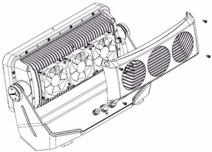
The three IP67-rated fans on the back of the LED unit of the spotlight must be regularly checked for functionality and, if necessary, cleaned. Disconnect the spotlight from the power supply (if necessary, switch off the whole installation). Loosen the 4 socket screws holding the fan cover to the LED unit using a suitable tool. Remove the fan cover from the LED unit, clean the fans and check that the fans can rotate freely. If compressed air is used, make sure that damage to the device is prevented (e.g. fans must be blocked in this case, as they could otherwise over-rev.). Clean the ventilation openings of the fan cover and fasten the cover again with the previously loosened screws.
If a fan should become blocked despite cleaning, take the spotlight out of operation and contact an authorised service centre.
natural_image
Technical line drawing of a mechanical fan assembly with cooling fins and mounting brackets (no text or symbols)OPTIONAL ACCESSORIES
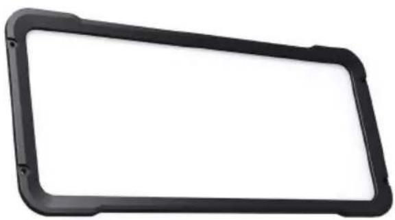
Diffusers
natural_image
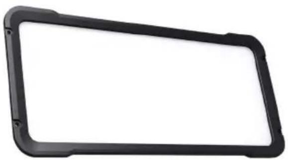
Black rectangular frame with rounded corners and a blank white space (no text or symbols)| Product number Diffusion angle | |
| CLZW600ISMLD20 25° | |
| CLZW600ISMLD40 45° | |
| CLZW600ISMLD100 100° | |
| CLZW600ISMLD6010 60° | x 10° |
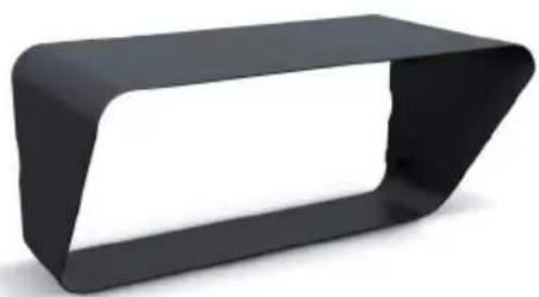
Glare shield (half top hat)
Product number CLZW600IHALFGS
natural_image
3D rendering of a black geometric object with a white cutout, resembling a stylized bench or bracket (no text or symbols)Display module with controls including 2 m connecting cable
Product number CLZIEXDISP
Mounting plate
Product number CLZW600IMP

natural_image
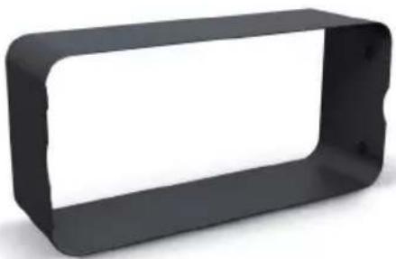
3D rendered image of a black plastic electronic component with mounting holes and a metallic edge (no text or symbols visible)Glare shield (full top hat)
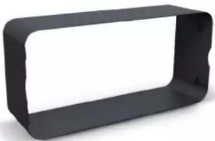
Product number CLZW600IFULLGS
natural_image
3D rendering of a black rectangular metal bracket with rounded corners and a white interior (no text or symbols)TECHNICAL DATA
| PRODUCT NUMBER: CLZW600i | |
| Product type: LED wash light | |
| Type: Outdoor spotlight | |
| Colour spectrum LED: RGBW | |
| No. of LEDs: 40 | |
| LED type: 15 W 4-in-1 SMD | |
| LED PWM frequency: 800 Hz, 1200 Hz, 2000 Hz, 3600 Hz, 12 kHz, 25 kHz (adjustable) | |
| Beam angle: 18° (35° field) | |
| Interfaces: Fixed 5-pin signal line (DMX In and Out), 2 m, with open ends for connection to an external module with OLED display and controls | |
| DMX mode: 2-channel CCT, 3-channel colour macro, 3-channel factory-calibrated, 4-channel user-calibrated, 6-channel factory-calibrated, 8-channel user-calibrated, 8-channel 8-bit, 10-channel, 15-channel | |
| DMX functions: Dimmer, dimmer fine, RGBW, RGBW fine, strobe, dimmer curves, colour temperature correction, dimmer response, colour macros, colour change, colour blending, system settings | |
| Standalone functions: | Colour mixing, colour macros, master/slave operation, auto programs, static (RGBW), tunable white, user colour, timer, strobe |
| System settings: | Rotate display by 180°, display lighting, DMX fail, dimmer curves, dimmer response, colour calibration, LED PWM frequency, fan control, factory reset |
| Control: | DMX512, RDM-enabled |
| Operating elements: | External module with OLED display and mode, enter, up, down (optionally available) |
| Display elements: | External module with OLED display and mode, enter, up, down (optionally available) |
| Operating voltage: | 100–240 V AC / 50–60 Hz |
| Power supply connection: | Fixed power cable H07RN-F, 3 x 1.5 mm2, 2 m, open ends |
| Electrical protection class: | 1 |
| Maximum power consumption: | 565 W |
| Inrush current: | 2.5 A @ 230 V / 5.6 A @ 100 V |
| Light intensity (@ 1 m, without diffuser): | 120,000 lx |
| Luminous flux (RGBW): | 21,000 lm |
| Efficiency: | 37.2 lm/W |
| Power factor: | 0.99 PF (120 V) / 0.96 PF (230 V) |
| Ambient temperature (in operation): | -15°C to +45°C |
| Housing material: die-cast aluminium | |
| Housing colour: Black | |
| Corrosion resistance: C5-M powder coating | |
| Housing cooling: 3 x IP67 fans | |
| Protection class: IP67 | |
| Cable glands: Protection class IP68 | |
| Impact resistance rating: IK08 | |
| Maximum installation height: Unlimited | |
| Projected area (EPA): 0.12 m2 (0.15 m2 with half top hat glare shield and mounting plate) | |
| Operating situation: As required | |
| Minimum distance to normal flammable materials: | 0.5 m |
| Minimum distance to illuminated surface: | 0.5 m |
| Dimensions (W x H x D, without bracket): | 449 x 291 x 161 mm |
| Weight (not including accessories): | 13 kg |
| Accessories supplied: Face spanner. 2 x Omega brackets and 4 x M8 x 25 mounting bolts plus U-washers. 4 x M4 x 18 socket screws for attaching the diffuser and glare shield | |
| Optional accessories: • External module with OLED display and controls incl. 2 m connection cable• Mounting plate with 4 x M4 x 25 socket screws• Diffusers (25°, 45°, 100°, 60° x 10°)• Glare shield half top hat• Glare shield full top hat | |
EXPLANATION OF IP PROTECTION CLASS
- An IP rating only reflects protection from solid objects and water. It does not describe general weather resistance, such as protection from UV radiation and temperature, etc.
- The first identification digit indicates protection from dust, solid objects and contact:
| IP2X | Protected against solid foreign bodies ≥ 12.5 mm in diameter |
| IP3X | Protected against solid foreign bodies ≥ 2.5 mm in diameter |
| IP4X | Protected against solid foreign bodies ≥ 1.0 mm in diameter |
| IP5X | Protected against dust in harmful quantities and completely protected against contact |
| IP6X | Are dust-tight and completely protected against contact |
- The second identification digit indicates protection from water:
| IPX0 no protection |
| IPX1 Protection against dripping water |
| IPX2 Protection against dripping water when the device is tilted up to 15° |
| IPX3 Protection against falling spray water up to 60° from the vertical |
| IPX4 Protection against splashing water on all sides |
| IPX5 Protection against water jets (nozzle) from any angle |
| IPX6 Protection against strong water jets |
| IPX7 Protection against temporary immersion |
- In addition, some device-specific measures such as covers and sealing caps are necessary in order to achieve the specified protection class (e.g. protective caps on unused connections).

The IP rating of the product can be found in the technical data and is printed on the device.
EXPLANATORY NOTES ON IK IMPACT RESISTANCE RATING
The IK impact resistance rating is a measure of the resistance of a housing (in the case of electrical equipment) to impact stress. It is standardised according to CEI EN 50102 and describes how much impact energy (in Joules) the housing can withstand without breaking.
| IK00 No impact resistance | |
| IK01 Impact resistance up to impact energy of 0.14 J | |
| IK02 Impact resistance up to impact energy of 0.2 J | |
| IK03 Impact resistance up to impact energy of 0.35 J | |
| IK04 Impact resistance up to impact energy of 0.5 J | |
| IK05 Impact resistance up to impact energy of 0.7 J | |
| IK06 Impact resistance up to impact energy of 1.0 J | |
| IK07 Impact resistance up to impact energy of 2.0 J | |
| IK08 Impact resistance up to impact energy of 5.0 J | |
| IK09 Impact resistance up to impact energy of 10.0 J | |
| IK10 Impact resistance up to impact energy of 20.0 J | |
| IK10+ Impact resistance up to impact energy of 50.0 J |

The impact resistance rating of the product can be found in the technical data and is printed on the device.
MINIMUM DISTANCE TO ILLUMINATED SURFACE

This symbol with distance specification in metres (m) indicates the minimum distance between the light head and the illuminated surface. In this example the distance is 0.5 m.
MINIMUM DISTANCE TO NORMALLY FLAMMABLE MATERIALS
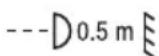
This symbol with distance specification in metres (m) indicates the minimum distance between the light head and normally flammable materials. In this example the distance is 0.5 m.
DISPOSAL

Packaging:
- Packaging can be fed into the reusable material cycle using the usual disposal methods.
- Please separate the packaging in accordance with the disposal laws and recycling regulations in your country.
Device:
- This device is subject to the European Directive on Waste Electrical and Electronic Equipment, as amended. WEEE Directive Waste Electrical and Electronic Equipment. Old appliances do not belong in household waste. The old device must be disposed of via an approved disposal company or a municipal disposal facility. Please observe the applicable regulations in your country!
- Observe all disposal laws applicable in your country.
- As a private customer, you can obtain information on environmentally-friendly disposal options from the seller of the product or the appropriate regional authorities.
MANUFACTURER'S DECLARATIONS
MANUFACTURER'S WARRANTY & LIMITATION OF LIABILITY
Adam Hall GmbH, Adam-Hall-Str. 1, D-61267 Neu Anspach / E-mail Info@adamhall.com / +49 (0)6081 / 9419-0. Our current warranty conditions and limitation of liability can be found at: https://cdn-shop.adamhall.com/media/pdf/Manufacturers-Declarations-CAMEO_DE_EN_ES_FR.pdf. Contact your sales partner for service.
CE CONFORMITY
Adam Hall GmbH hereby confirm that this product meets the following guidelines (where applicable):
Low-Voltage Directive (2014/35/EU)
EMC Directive (2014/30/EU)
RoHS (2011/65/EU)
RED (2014/53/EU)
CE CONFORMITY DECLARATION
Declarations of conformity for products subject to the LVD, EMC, RoHS Directive can be requested from info@adamhall.com. Declarations of conformity for products subject to RED can be downloaded from www.adamhall.com/compliance/.
UKCA- CONFORMITY
Hereby, Adam Hall Ltd. declares that this product meets the following guidelines (where applicable)
Electrical Equipment (Safety) Regulations 2016
Electromagnetic Compatibility Regulations 2016 (SI 2016/1091)
The Restriction of the Use of Certain Hazardous Substances in Electrical and Electronic Equipment
Regulation 2012 (SI 2012/3032)
Radio Equipment Regulations 2017(SI 2016/2015)
UKCA- DECLARATION OF CONFORMITY
Products that are subject to Electrical Equipment(Safety)Regulation 2016, EMC Regulation 2016 or RoHS Regulation can be requested at info@adamhall.com.
Products that are subject to the Radio Equipments Regulations 2017 (SI2017/1206) can be downloaded from www.adamhall.com/compliance/
DEUTSCH
natural_image
Line drawing of a mechanical device with a connector and cable (no text or symbols)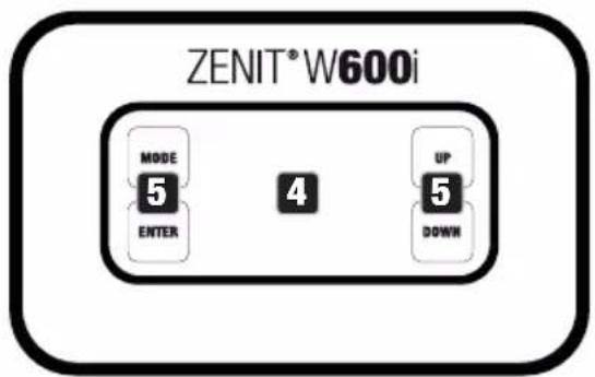
DISPLAY-MODUL
15CH Full Access 10CH Full Access 8CH 8Bit 8CH User-Calibrated 6CH Factory-Calibrated 4CH User-Calibrated 3CH Factory-Calibrated 3CH Color Macro 2CH CCT Factory-Calib
FARBTEMPERATUR (Tunable White)
BENUTZER-PRESETS (User Color)

TIMER-FUNKTION (Timer)
natural_image
Technical line drawing of a vehicle air conditioning unit with labeled components (A and B), showing internal fan structures and mounting hardware (no text or symbols beyond labels)OPTIONALES ZUBEHÖR MONTIEREN
natural_image
Technical line drawings of a camoo-based device with circular components and mounting brackets (no text or symbols)MONTAGEPLATTE
natural_image
Technical line drawing of a mechanical assembly with internal components and mounting holes (no text or symbols)SCHEINWERFER MITTELS OPTIONALER MONTAGEPLATTE INSTALLIEREN
natural_image
Technical line drawing of a front-mounted industrial fan or heat exchanger unit with three circular vented chambers (no text or symbols)natural_image
Technical line drawing of a car air conditioning unit with multiple fans and cooling fins (no text or labels)OPTIONALES ZUBEHÖR
natural_image
Black rectangular frame with rounded corners and a blank white space (no text or symbols)| Artikelnummer Streuwinkel | |
| CLZW600ISMLD20 25° | |
| CLZW600ISMLD40 45° | |
| CLZW600ISMLD100 100° | |
| CLZW600ISMLD6010 60° | x10° |
natural_image
3D rendering of a black geometric object with a white cutout, resembling a stylized bench or bracket (no text or symbols)Montageplatte
natural_image
3D rendered image of a black plastic electronic component with mounting holes and a triangular base (no text or symbols visible)Blendschutz (full top hat)
Artikelnummer CLZW600IFULLGS
natural_image
3D rendering of a black rectangular metal bracket with rounded corners (no text or symbols)TECHNISCHE DATEN
natural_image
Line drawing of a device with a connector and cable, no text or symbols present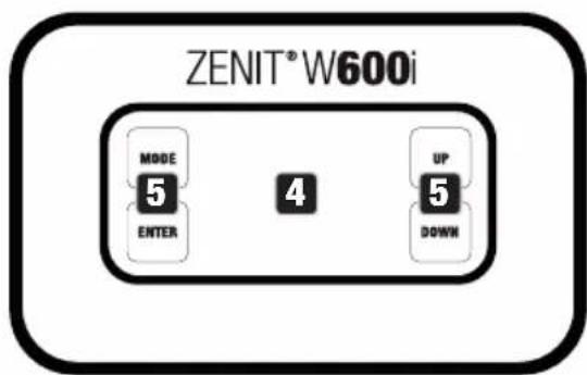
MODULE D'AFFICHAGE
RÉGLAGE DU MODE DE FONCTIONNEMENT STANDALONE
MODE DE FONCTIONNEMENT AUTO (Program 1 – Program 6)
TEMPÉRATURE CHROMATIQUE (Tunable White)
natural_image
Technical line drawing of a vehicle air conditioning enclosure with two fans and labeled components (A and B), no text or symbols present.MONTAGE DES ACCESSOIRES EN OPTION
DIFFUSEUR ET PROTECTION ANTI-ÉBLOUISSEMENT
natural_image
Technical line drawing of a camoo device enclosure with circular grid layout and mounting brackets (no text or symbols)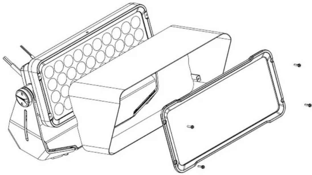
natural_image
Technical line drawing of a mechanical device with circular components and mounting brackets (no text or symbols)PLAQUE DE MONTAGE
natural_image
Technical line drawing of a mechanical assembly with internal components and mounting holes (no text or symbols)INSTALLATION DU PROJECTEUR À L'AIDE DE LA PLAQUE DE MONTAGE EN OPTION
natural_image
Technical line drawing of a vehicle front-mounted air heater with three circular vented chambers (no text or symbols)ENTRETIEN, MAINTENANCE ET RÉPARATION
natural_image
Technical line drawing of a car air conditioning unit with multiple fans and cooling fins (no text or labels)ACCESSOIRES EN OPTION
natural_image
Black rectangular frame with rounded corners and a blank white space (no text or symbols)| Référence Angle de diffusion | |
| CLZW600ISMLD20 25° | |
| CLZW600ISMLD40 45° | |
| CLZW600ISMLD100 100° | |
| CLZW600ISMLD6010 60° | x10° |
Plaque de montage
natural_image
3D rendered image of a black plastic electronic component with mounting holes and a slot (no text or symbols visible)Protection anti-éblouissement (half top hat)
natural_image
3D rendered black geometric object with a white cutout, no visible text or symbolsProtection anti-éblouissement (full top hat)
natural_image
3D rendering of a black rectangular metal bracket with rounded corners and a white interior (no text or symbols)CARACTÉRISTIQUES TECHNIQUES
Directive CEM (2014/30/UE)
RoHS (2011/65/UE)
RED (2014/53/UE)
DÉCLARATION DE CONFORMITÉ CE
natural_image
Line drawing of a device with a connector and cable, no text or symbols present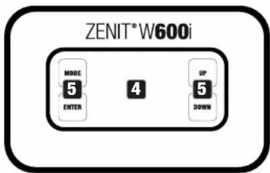
MÓDULO DE PANTALLA
TEMPERATURA DE COLOR (Tunable White)
natural_image
Technical line drawing of a vehicle chassis with internal fan structures and mounting brackets (no text or symbols)MONTAJE DE LOS ACCESORIOS OPCIONALES
DIFUSOR Y PROTECTOR ANTIDESLUMBRAMIENTO
natural_image
Technical line drawing of a mechanical assembly with internal components and mounting holes (no text or symbols)natural_image
Technical line drawing of a vehicle front-mounted air heater with three circular vented chambers (no text or symbols)natural_image
Technical line drawing of a mechanical fan assembly with cooling fins and mounting brackets (no text or symbols)natural_image
Black rectangular frame with rounded corners and a blank white space (no text or symbols)| N.° de articulo Ángulo de dispersión | |
| CLZW600ISMLD20 25° | |
| CLZW600ISMLD40 45° | |
| CLZW600ISMLD100 100° | |
| CLZW600ISMLD6010 60° | x 10° |
Protector antideslumbramiento (half top hat)
natural_image
3D rendering of a black geometric object with a white cutout, resembling a stylized bench or bracket (no text or symbols)Placa de montaje
natural_image
3D rendered image of a black plastic electronic component with mounting holes and a triangular cutout (no text or symbols)Protector antideslumbramiento (full top hat)
natural_image
3D rendering of a black rectangular metal bracket with white interior (no text or symbols)DATOS TÉCNICOS
natural_image
Line drawing of a mechanical device with a cylindrical connector and a rectangular housing (no text or symbols)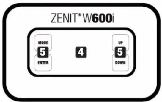
MODUŁ WYŚWIETLACZA
PRZEWÓD SYGNAŁOWY I SIECIOWY
TEMPERATURA BARWOWA (Tunable White)
USTAWIENIA WSTĘPNE UŻYTKOWNIKA (User Color)
FUNKCJA TIMERA (Timer)
natural_image
Technical line drawing of a vehicle chassis with internal fan structures and mounting brackets (no text or symbols)MONTAŻ OPCJONALNYCH AKCESORIÓW
TARCZA DYFUZORA I OSŁONA PRZECIWODBLASKOWA
natural_image
Technical line drawing of a mechanical assembly with internal components and mounting holes (no text or symbols)INSTALĄCJA REFLEKTORA PRZY UŻYCIU OPCJONALNEJ PŁYTY MONTAŻOWEJ
natural_image
Technical line drawing of a vehicle front-mounted air heater with three circular vented chambers (no text or symbols)CZYSZCZENIE, KONSERWACJA I NAPRAWY
natural_image
Technical line drawing of a car air conditioning unit with multiple fans and cooling fins (no text or labels)AKCESORIA DODATKOWE
Dyfuzory
natural_image
Black rectangular frame with rounded corners and a blank white space (no text or symbols)| Numer artykułu Kąt rozproszenia | |
| CLZW600ISMLD20 25° | |
| CLZW600ISMLD40 45° | |
| CLZW600ISMLD100 100° | |
| CLZW600ISMLD6010 60° | x10° |
natural_image
3D rendered image of a black plastic electronic component with mounting holes and a slot (no text or symbols visible)natural_image
3D rendering of a black geometric object with a white cutout, resembling a stylized bench or bracket (no text or symbols)natural_image
3D rendering of a black rectangular metal bracket with white interior (no text or symbols)DANE TECHNICZNE
natural_image
Line drawing of a device with a connector and cable, no text or symbols present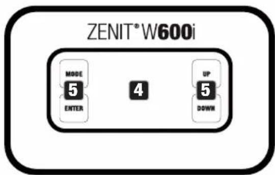
MODULO DISPLAY
PRESET UTENTE (User Color)
natural_image
Technical line drawing of a camoo device with circular grid layout and labeled components (no text or symbols beyond labels)natural_image
Technical line drawing of a vehicle air conditioning enclosure with two fans and labeled components (A and B), no text or symbols present.natural_image
Technical line drawing of a mechanical assembly with internal components and mounting holes (no text or symbols)natural_image
Technical line drawing of a vehicle front-mounted air heater with three circular vented chambers (no text or symbols)natural_image
Technical line drawing of a car air conditioning unit with multiple fans and cooling fins (no text or labels)ACCESSORI OPZIONALI
natural_image
Black rectangular frame with rounded corners and a blank white space (no text or symbols)natural_image
3D rendered image of a black plastic electronic component with mounting holes and a slot (no text or symbols visible)natural_image
3D rendering of a black geometric object with a white cutout, resembling a stylized bench or bracket (no text or symbols)natural_image
3D rendering of a black rectangular metal bracket with rounded corners and a white interior (no text or symbols)DATI TECNICI
| 8 CH User-Calibrated 16 Bit | ||||||
| Ch. Function Values Sub-Group | ||||||
| 1 Red | 000 - 255 0% to 100% | Red | ||||
| 2 Red | fine 000 - 255 0% to 100% | |||||
| 3 Green | 000 - 255 0% to 100% | Green | ||||
| 4 Green | fine 000 - 255 0% to 100% | |||||
| 5 Blue 000 - 255 0% to 100% | Blue | |||||
| 6 Blue fine 000 - 255 0% to 100% | ||||||
| 7 White 000 - 255 0% to 100% | White | |||||
| 8 White fine 000 - 255 0% to 100% | ||||||
| 6 CH Factory-Calibrated 16 Bit | ||||||
| Ch. Function Values Sub-Group | ||||||
| 1 Red | 000 - 255 0% to 100% | Red | ||||
| 2 Red | fine 000 - 255 0% to 100% | |||||
| 3 | Green | 000 - 255 0% to 100% | Green | |||
| 4 | Green fine | 000 - 255 0% to 100% | ||||
| 5 Blue | 000 - 255 0% to 100% | Blue | ||||
| 6 Blue | fine 000 - 255 0% to 100% | |||||
| 4 CH User-Calibrated 8 Bit | ||||||
| Ch. Function Values Sub-Group | ||||||
| 1 Red | 000 - 255 0% to 100% | Red | ||||
| 2 | Green | 000 - 255 0% to 100% | Green | |||
| 3 Blue | 000 - 255 0% to 100% | Blue | ||||
| 4 White | 000 - 255 0% to 100% | White | ||||
| 3 CH Factory-Calibrated 8 Bit | ||||||
| Ch. Function Values Sub-Group | ||||||
| 1 Red | 000 - 255 0% to 100% | Red | ||||
| 2 | Green | 000 - 255 0% to 100% | Green | |||
| 3 Blue | 000 - 255 0% to 100% | Blue | ||||
| 3 CH Color Macros | ||||||
| Ch. Function Values Sub-Group | ||||||
| 1 | Dimmer | 000 - 2 | 55 0% to 100% | Dimmer | ||
| 2 | Strobe functions | 000 - 0 | 05 Strobe open | Multifunctional strobe | ||
| 006 - 0 | 10 Strobe closed | |||||
| 011 - 0 | 33 Pulse random slow -> fast | |||||
| 034 - 0 | 56 Ramp up random slow -> fast | |||||
| 057 - 0 | 79 Ramp down random slow -> fast | |||||
| 080 - 1 | 02 Random strobe effect slow -> fast | |||||
| 103 - 1 | 27 | Strobe break effect, 5s......1s (short burst with break) | ||||
| 128 - 2 | 50 Strobe slow -> fast <1Hz - 20Hz | |||||
| 251 - 2 | 55 Strobe open | |||||
| 3 Color Macros | 000 - 005 Color off | Color Macros | ||||
| 006 - 013 Red | ||||||
| 014 - 021 Amber | ||||||
| 022 - 029 Yellow warm | ||||||
| 030 - 037 Yellow | ||||||
| 038 - 045 Green | ||||||
| 046 - 053 Turquoise | ||||||
| 054 - 061 Cyan | ||||||
| 062 - 069 Blue | ||||||
| 070 - 077 Lavender | ||||||
| 078 - 085 Mauve | ||||||
| 086 - 093 Magenta | ||||||
| 094 - 101 Pink | ||||||
| 102 - 109 Warm White | ||||||
| 110 - 117 White | ||||||
| 118 - 125 Cold White | ||||||
| 126 - 127 Color Jumping stop | ||||||
| 128 - 191 | Color Jumping speed slow -> fast / color 1 -> 12 | |||||
| 192 - 255 | Color Fading speed slow -> fast / color 1 -> 12 | |||||
| 2 CH CCT Factory-Calibrated | ||||||
| Ch. Function Values Sub-Group | ||||||
| 1 Dimmer 000 - 255 0% to 100% | Dimmer | |||||
| 2 Color Temperature | 000 - 005 off | Color Temperature | ||||
| 006 - 006 Warm White | ||||||
| 007 - 046 Warm White - 2700 k | ||||||
| 047 - 047 Bulb White (2700 k) | ||||||
| 048 - 087 2700 k - 3200 k | ||||||
| 088 - 088 Halogen White (3200 k) | ||||||
| 089 - 128 3200 k - 4000 k | ||||||
| 129 - 129 Neutral White (4000 k) | ||||||
| 130 - 169 4000 k - 5600 k | ||||||
| 170 - 170 Studio White (5600 k) | ||||||
| 171 - 210 5600 k - 6500 k | ||||||
| 211 - 211 Daylight White (6500 k) | ||||||
| 212 - 251 6500 k - Cold Daylight | ||||||
| 252 - 255 Cold Daylight | ||||||
EN: (1*) After the adjustments have been made, set the value to 000 to avoid disturbance by endless function call.
DE: (1*) Nachdem die Einstellungen vorgenommen wurden, stellen Sie den Wert auf 000 ein, um Störungen durch endlosen Funktionsaufruf zu vermeiden.
FR: (1*) Une fois les ajustements effectués, réglez la valeur sur 000 pour éviter les perturbations par appel de fonction sans fin.
ES: (1*) Después de realizar los ajustes, establezca el valor en 000 para evitar perturbaciones mediante una llamada de función sin fin.
PL: (1*) Po dokonaniu ustawień ustaw wartość na 000, aby uniknąć zakłóceń przez niekończące się wywołanie funkcji.
IT: (1*) Dopo aver effettuato le regolazioni, impostare il valore su 000 per evitare disturbi causati da una chiamata a funzione infinita.

- ZENIT® W600i
- CONTENTS / INHALTSVERZEICHNIS / TABLE DES MATIÈRES / CONTENIDO / SPIS TREŚCI / CONTENUTO
- ENGLISH
- DEUTSCH
- ITALIANO
- INFORMATION ON THIS USER MANUAL
- INTENDED USE
- DEFINITIONS AND SYMBOL EXPLANATIONS
- SAFETY INSTRUCTIONS
- HAZARD:
- WARNING:
- CAUTION:
- CAUTION! IMPORTANT INFORMATION REGARDING LIGHTING PRODUCTS!
- INSTRUCTIONS FOR INSTALLATION EQUIPMENT
- NOTES FOR INSTALLATION DEVICES
- FEATURES
- CONTROL FUNCTIONS
- DELIVERY CONDITION
- CONNECTIONS, OPERATING AND DISPLAY ELEMENTS
- DMX
- CONNECTION FOR DISPLAY MODULE
- POWER
- DISPLAY MODULE
- OLED DISPLAY
- TOUCH-SENSITIVE CONTROLS
- MODE
- ENTER
- UP and DOWN
- PRESSURE EQUALISATION ELEMENT
- HOUSING FAN
- SIGNAL AND POWER CABLE
- PLEASE NOTE
- OPERATION
- MAIN DISPLAY
- CONFIGURING DMX START ADDRESS (DMX Address)
- CONFIGURING DMX MODE (DMX Mode)
- CONFIGURE STANDALONE MODE
- AUTO MODE (Program 1 to Program 6)
- COLOUR MACROS (Color Macro)
- STATIC MODE (Static)
- COLOUR TEMPERATURE (Tunable White)
- USER PRESETS (User Color)
- TIMER FUNCTION (Timer)
- DEVICE SETTINGS (Settings)
- SYSTEM INFORMATION (System Info)
- MANUAL LOCKING FUNCTION
- ADJUSTING LIGHT HEAD TILT
- INSTALLATION AND TRUSS MOUNTING
- INSTALLATION OF OPTIONAL ACCESSORIES
- DIFFUSER AND GLARE SHIELD
- MOUNTING PLATE
- INSTALL SPOTLIGHT WITH OPTIONAL MOUNTING PLATE
- CARE, MAINTENANCE AND REPAIR
- CARE (carried out by user)
- MAINTENANCE AND REPAIR (by qualified personnel only)
- Clean fan
- OPTIONAL ACCESSORIES
- Glare shield (half top hat)
- Display module with controls including 2 m connecting cable
- Glare shield (full top hat)
- EXPLANATION OF IP PROTECTION CLASS
- EXPLANATORY NOTES ON IK IMPACT RESISTANCE RATING
- MINIMUM DISTANCE TO ILLUMINATED SURFACE
- MINIMUM DISTANCE TO NORMALLY FLAMMABLE MATERIALS
- DISPOSAL
- Packaging:
- Device:
- MANUFACTURER'S DECLARATIONS
- MANUFACTURER'S WARRANTY & LIMITATION OF LIABILITY
- CE CONFORMITY
- CE CONFORMITY DECLARATION
- UKCA- CONFORMITY
- UKCA- DECLARATION OF CONFORMITY
- DISPLAY-MODUL
- FARBTEMPERATUR (Tunable White)
- BENUTZER-PRESETS (User Color)
- TIMER-FUNKTION (Timer)
- OPTIONALES ZUBEHÖR MONTIEREN
- MONTAGEPLATTE
- SCHEINWERFER MITTELS OPTIONALER MONTAGEPLATTE INSTALLIEREN
- OPTIONALES ZUBEHÖR
- Blendschutz (full top hat)
- MODULE D'AFFICHAGE
- RÉGLAGE DU MODE DE FONCTIONNEMENT STANDALONE
- MODE DE FONCTIONNEMENT AUTO (Program 1 – Program 6)
- TEMPÉRATURE CHROMATIQUE (Tunable White)
- MONTAGE DES ACCESSOIRES EN OPTION
- DIFFUSEUR ET PROTECTION ANTI-ÉBLOUISSEMENT
- PLAQUE DE MONTAGE
- INSTALLATION DU PROJECTEUR À L'AIDE DE LA PLAQUE DE MONTAGE EN OPTION
- ENTRETIEN, MAINTENANCE ET RÉPARATION
- ACCESSOIRES EN OPTION
- Protection anti-éblouissement (half top hat)
- Protection anti-éblouissement (full top hat)
- DÉCLARATION DE CONFORMITÉ CE
- MÓDULO DE PANTALLA
- TEMPERATURA DE COLOR (Tunable White)
- MONTAJE DE LOS ACCESORIOS OPCIONALES
- DIFUSOR Y PROTECTOR ANTIDESLUMBRAMIENTO
- Protector antideslumbramiento (half top hat)
- Placa de montaje
- Protector antideslumbramiento (full top hat)
- MODUŁ WYŚWIETLACZA
- PRZEWÓD SYGNAŁOWY I SIECIOWY
- TEMPERATURA BARWOWA (Tunable White)
- USTAWIENIA WSTĘPNE UŻYTKOWNIKA (User Color)
- FUNKCJA TIMERA (Timer)
- MONTAŻ OPCJONALNYCH AKCESORIÓW
- TARCZA DYFUZORA I OSŁONA PRZECIWODBLASKOWA
- INSTALĄCJA REFLEKTORA PRZY UŻYCIU OPCJONALNEJ PŁYTY MONTAŻOWEJ
- CZYSZCZENIE, KONSERWACJA I NAPRAWY
- AKCESORIA DODATKOWE
- MODULO DISPLAY
- PRESET UTENTE (User Color)
- ACCESSORI OPZIONALI
Brand : Cameo
Model : ZENIT W600i
Category : Lighting