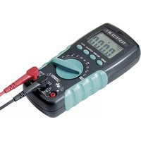
TESTFOX M-1 - Multimeter Phoenix Contact - Free user manual and instructions
Find the device manual for free TESTFOX M-1 Phoenix Contact in PDF.


| Product Type | Digital Multimeter |
| Brand | Phoenix Contact |
| Model | TESTFOX M-1 |
| Dimensions (L x W x H) | 156 x 74 x 44 mm (with hanging device) |
| Weight | 320 g (with hanging device and batteries) |
| Power Supply | 2 batteries 1.5 V type R3 (IEC LR06) |
| Battery Life | Approx. 250 hours (alkaline batteries) |
| Display | LCD 3½ digits, height 16 mm, maximum value 2000 |
| Main Functions | DC/AC voltage, DC/AC current (up to 10 A), resistance, capacitance, frequency, temperature, diode test, continuity test, non-contact voltage indicator |
| DC Voltage Ranges | 200 mV / 2 V / 20 V / 200 V / 1000 V, resolution 100 µV to 1 V |
| AC Voltage Ranges | 200 mV / 2 V / 20 V / 200 V / 750 V, resolution 100 µV to 1 V |
| DC/AC Current Ranges | 2 A / 10 A, resolution 1 mA / 10 mA (TESTFOX M-1) |
| Resistance Ranges | 200 Ω / 2 kΩ / 20 kΩ / 200 kΩ / 2 MΩ / 20 MΩ |
| Capacitance Ranges | 2 nF / 20 nF / 200 nF / 2 µF / 20 µF / 200 µF / 2 mF |
| Frequency Ranges | 2 kHz / 20 kHz / 200 kHz / 2 MHz / 20 MHz |
| Temperature Ranges | -20 °C to 800 °C (with type K adapter) |
| Basic Accuracy (DC Voltage) | ±(0.5 % of reading + 2 digits) |
| Overload Protection | Fuse 10 A / 600 V, 50 kA (TESTFOX M-1) |
| Overvoltage Category | CAT III 600 V, CAT II 1000 V |
| Protection Rating | IP 30 |
| Operating Temperature | 0 °C to 50 °C (depending on humidity) |
| Storage Temperature | -15 °C to +60 °C (batteries removed) |
| Supplied Accessories | 2 safety measuring cables (red/black, 1.4 m), type K temperature adapter, hanging device, case, 2 batteries, spare fuse, user manual |
Frequently Asked Questions - TESTFOX M-1 Phoenix Contact
User questions about TESTFOX M-1 Phoenix Contact
0 question about this device. Answer the ones you know or ask your own.
Ask a new question about this device
Download the instructions for your Multimeter in PDF format for free! Find your manual TESTFOX M-1 - Phoenix Contact and take your electronic device back in hand. On this page are published all the documents necessary for the use of your device. TESTFOX M-1 by Phoenix Contact.
USER MANUAL TESTFOX M-1 Phoenix Contact
Fig. 2: Direct voltage measurement
Fig. 2: Mesure de tension continue
Fig. 2: Medición de tension contínua
Fig. 3: Alternating voltage measurement
Fig. 3: Mesure de tension alternative
Fig. 4: DC current measurement
Fig. 5: AC current measurement
Fig. 6: Resistance measurement
Fig. 8: Continuity testing with buzzer
Fig. 9: Capacity testing
Fig. 10: Frequency measurement
Fig. 11: Temperature measurement
fig. 12: Voltage indicator with buzzer
natural_image
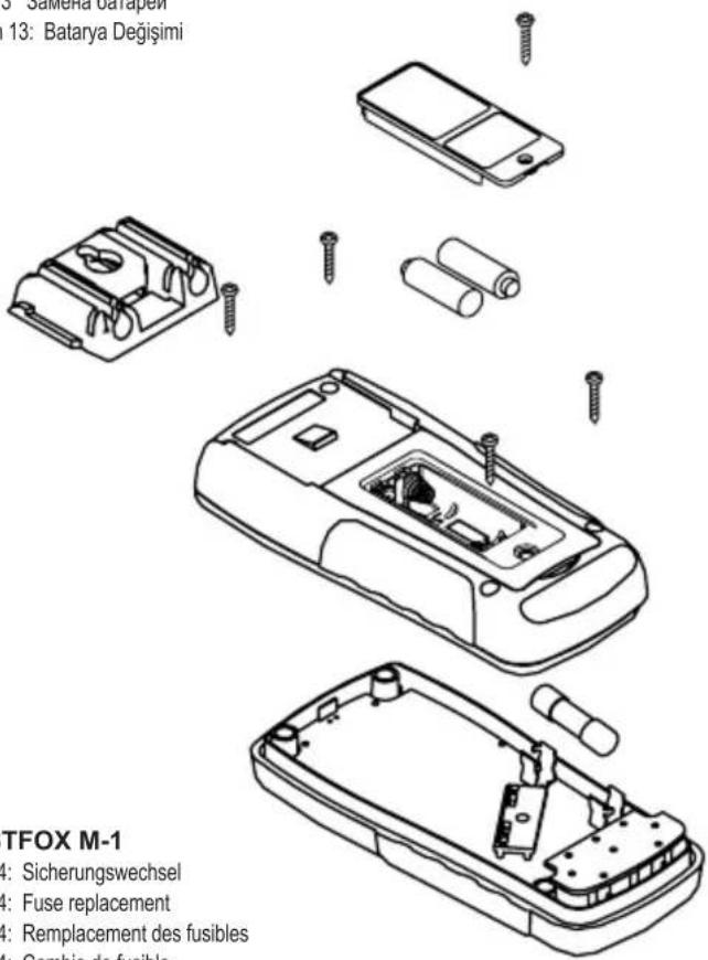
Exploded view diagram of a mobile phone case showing internal components and battery pack (no text or labels)Bild 13: Batteriewechsel
Fig. 13: Battery replacement
Fig. 13: Remplacement de la pile
Fig. 13: Cambio de pila
obr. 13: Výměna baterií
figur 13: Batteriskift
σχήμα 13: Αντικατάσταση μπαταρίας
13 ábra: Telepcsere
ill. 13: Sostituzione batterie
Fig. 13: Vervanging van de batterijen
Rys.13: Wymiana baterii
рис. 13 Замена батареи
Resim 13: Batarya Değişimi
TESTFOX M-1
Fig. 14: Fuse replacement
natural_image
Technical line drawing of a mechanical component with no visible text or symbolsFig. 15: Wrapping up the safety test leads
natural_image
Technical line drawing of a mechanical device with two views: top shows a cylindrical component mounted on a stand, bottom shows a cylindrical housing with horizontal ridges (no text or symbols)- DC voltage measurements
- AC voltage measurements
- DC current measurements (TESTFOX M-1)
- AC current measurements (TESTFOX M-1)
- resistance measurements
- diode tests
- continuity tests
- capacity measurements ( TESTFOX M-1)
- frequency measurements (TESTFOX M-1)
- temperature measurements (TESTFOX M-1)
Table of contents
- User instructions
- Safety instructions
- Scope of delivery
- Device description
- General information
- Ambient conditions
- Electrical specifications
- Measuring with the TESTFOX M/ M-1
- Maintenance
- Using the folding support and the suspension fixture
- Technical data of measuring accessories
- Environmental protection
1. User information
This operating manual is intended for
- skilled electricians and
- electrotechnically trained personnel.
The TESTFOX M/ M-1 is intended for measurements under dry ambient conditions. It must not be used in electrical circuits with a nominal voltage higher than 1000 V DC and 750 V AC (see section 6 „Ambient conditions“ for details). The following symbols are used in this operating manual and on the TESTFOX M/ M-1:

Warning of electrical danger!
Indicates instructions which must be followed to avoid danger to persons.

Important, must comply with documentation!
This symbol indicates that the information provided in the operating manual must be complied with in order to avoid risks.

This symbol on the TESTFOX M/ M-1 indicates that the
TESTFOX M/ M-1 is equipped with protective insulation (protection class II).

This symbol on the TESTFOX M-1 indicates built-in fuses.

This symbol appears on the display to indicate a discharged battery.

This symbol designates the „diode test“ range.

This symbol designates the "continuity test" field.
The buzzer is intended for acoustic result output.

This symbol indicates the „capacity test“ field.

(DC) Direct voltage or current

(AC) Alternating voltage or current

Ground (voltage against ground).
2. Safety instructions
The instrument is built and tested in accordance with
and has left the factory in perfectly safe technical condition.
To preserve this condition and to ensure safe operation of the device, the user must observe the notes and warnings given in these instructions at all times.

The device must be used in electrical circuits of overvoltage category II with a conductor for a maximum of 1000 V to earth or of overvoltage category III with a conductor for a maximum of 600 V to earth only.
Please observe that work on live parts and electrical components of all kinds is dangerous!
Even low voltages of 30 V AC and 60 V DC may be dangerous to human life.

Before starting the current clamp multimeter, always check the device as well as all cables for damages.
If it can be assumed that safe operation is no longer possible, switch the device off immediately and secure it against unintended operation.
Safe operation can be assumed to be no longer possible, if
- the device or the measuring lines exhibit visible damages,
- the device no longer works,
- the device has been stored under unfavourable conditions for a longer period of time,
- the device was exposed to extraordinary stress during transport.

In order to prevent danger
- do not touch the bare measuring probe tips of the measuring lines,
- insert the measuring lines into the respectively designated measuring sockets of the multimeter.
3. Scope of delivery
The scope of delivery of the TESTFOX M/ M-1 comprises:
3.1 One TESTFOX M/ M-1,
3.2 One safety measuring line, red (L = 1.4 m; probe tip ∅ = 4 mm),
3.3 One safety measuring line, black (L = 1.4 m; probe tip ∅ = 4 mm),
3.4 One measuring adapter with wire temperature sensor type K (TESTFOX M-1)
3.5 One rubber suspension fixture,
3.6 One compact protective pouch,
3.7 Two 1.5 V micro (AAA) batteries are integrated into the device,
3.8 One fuse for initial assembly is integrated into the device
( TESTFOX M-1),
3.9 One operating manual.
Parts subject to wear:
- The TESTFOX M/ M-1 is supplied by means of two integrated 1.5 V micro (AAA) batteries (IEC 6 LR 03).
- The TESTFOX M-1 is equipped with a fuse for overload protection:
One quick-acting fuse, nominal current 10 A (600 V), 50 kA
- The safety measuring lines ATL-2 mentioned above (tested accessories) comply with CAT III 1000 V and are approved for a current of 10 A.
4. Device description
See figure 1a, 1b: Device front
The display and operating elements shown in figures 1a and 1b are designated as follows:
① Digital display, displaying measured value and range exceedance,
② Polarity indication,
③ Battery indication, appears in case of discharged battery,
4 MIN/ MAX key, storage of the highest and lowest measured value (TESTFOX M-1),
⑤ VoltSensor key, for determining AC voltage to earth,
6 RANGE key, switch-over between automatic/ manual measuring range,
⑦ HOLD key, storage of the displayed measured value,
8 Rotary switch, for selecting the measuring function,
⑨ Jack (positive 1), for V, Ω, -Hz,
⑩ COM jack, common jack for current/voltage/resistance/frequency/temperature/capacity measurements, continuity and diode tests,
11 Jack (positive ^1 ), for A range, for currents up to 10 A (TESTFOX M-1),
⑫ Suspension fixture
13 LED for voltage indicator
1) This is what the automatic polarity indication for DC current and voltage refers to
5. General information
5.1 General information on the multimeter
5.1.1 The digital display ① is a 3½-digit LC display with a font size of 16 mm and a decimal point. The highest numerical value to be displayed is 2000.
5.1.2 The polarity indication ② works automatically. Only a polarity contrary to the jack definition is indicated with “-”.
5.1.3 The range exceedance is indicated by "0L" or "-0L" and partly by an acoustic warning.
Attention, no indication and warning in case of overload!
5.1.4 The „MAX/ MIN“ key function ④ automatically determines and stores the highest and the lowest measured value. Preselect the measuring range by means of the „RANGE“ key, if necessary. By pressing the key, the following values are displayed:
„MAX“ shows the highest stored value and „MIN“ the lowest stored value. The continuous determination of the MAX/ MIN value can be stopped or started by pressing the „HOLD“ key ⑦. By pressing the „MAX/ MIN“ key for approx. 1 second, you can switch back to normal mode.
5.1.5 The „RANGE“ key 6 is intended for shifting the manual measuring ranges and masking the „AUTO“ symbol on the display at the same time. Select the automatic range selection by pressing the key for approx. 1 second („AUTO“ is shown on the display).
5.1.6 Measured value storage „HOLD“: Press the “HOLD” key ⑦ to store the measuring result. At the same time, the display shows the “HOLD” symbol. Press the key again to switch back to the measuring mode.
5.1.7 The nominal measuring rate of the TESTFOX M/ M-1 is 2 measurements per second for the digital display.
5.1.8 The TESTFOX M/ M-1 can be switched on or off by means of the rotary switch ⑧. Switched off: position „OFF“.
5.1.9 The TESTFOX M/ M-1 switches off automatically after approx. 10 minutes (APO, Auto-Power-Off). It is switched on again if a key or the rotary switch is operated. A buzzer tone indicates that the device is switched off automatically. Automatic switch-off can be deactivated by pressing the „RANGE“ key and by simultaneously switching on the TESTFOX M/ M-1 from the switching position „OFF“.
5.1.10 Temperature coefficient of the measured value: 0.15 x (stated measuring accuracy)/°C < 18 °C or >28 °C, related to the value for the reference temperature of 23 °C.
5.1.11 The TESTFOX M/ M-1 is supplied by means of two 1.5 V micro (AAA) batteries (IEC 6 LR 03).
5.1.12 If the battery voltage falls below the specified operating voltage of the TESTFOX M/ M-1, a battery symbol ③ appears on the display ①.
5.1.13 The battery life is approx. 250 hours (alkaline battery).
5.1.14 Dimensions of the device: (L x W x H) = 156 x 74 x 44 mm with suspension fixture Weight: 320 g with suspension fixture and battery
5.1.15 The safety measuring lines are designed in 4 mm plug-in technology. The enclosed safety measuring lines are explicitly intended for the nominal voltage and the nominal current of the TESTFOX M/ M-1.
5.1.16 The TESTFOX M/ M-1 can be set up by means of a foldable support or can be attached by means of the suspension fixture.
5.1.17 The TESTFOX M/ M-1 is equipped with a detector as voltage indicator at its top side to localize earthed AC voltages.
6. Ambient conditions
- The TESTFOX M/ M-1 is intended for measurements under dry ambient conditions,
- Maximum barometric height for measurements: 2000 m,
- Overvoltage category / installation category: IEC 60664-1/ IEC 61010-1 → 600 V category III; 1000 V category II,
- Contamination class: 2,
- Protection category: IP 30 DIN VDE 0470-1 IEC/EN 60529 IP 30 means: Protection against access to dangerous parts and protection against solid impurities of a diameter > 2.5 mm, (3 – first index). No protection against water, (0 – second index).
- Operating temperature and relative air humidity:
For operating temperatures from 0 °C to 30 °C: relative air humidity less than 80 %,
For operating temperatures from 31 °C to 40 °C: relative air humidity less than 75 %,
For operating temperatures from 41 °C to 50 °C: relative air humidity less than 45 %,
- Storage temperature: The TESTFOX M/ M-1 can be stored at temperatures between - 15 °C and + 60 °C (air humidity of 0 to 80 %). During storage, the battery should be removed.
7. Electrical specifications
Note: The measuring accuracy is specified as the sum of:
- a relative part of the measured value and
- a number of digits (i.e. counting steps of the last digit).
This measuring accuracy applies for temperatures from 18 °C to 28 °C and a relative air humidity less than 80 %.
7.1 DC voltage ranges
The input resistance is 10 MΩ.
| Measuring range ^3 | Resolution | Measuring accuracy | Overload protection |
| 200 mV | 100 μV ± (0.5 % of the measured value + 2 digits) | 1000 V | DC |
| 2 V | 1 mV ± (0.5 % of the measured value + 2 digits) | 1000 V | DC |
| 20 V | 10 mV | ± (0.5 % of the measured value + 2 digits) | 1000 V |
| 200 V | 100 mV | ± (0.5 % of the measured value + 2 digits) | 1000 V |
| 1000 V | 1 V | ± (0.5 % of the measured value + 2 digits) | 1000 V |
7.2 AC voltage ranges
The input resistance is 10 MΩ in parallel 100 pF.
| Measuring range *3 | Resolution | Measuring accuracy *1 within the frequency range 50 Hz - 300 Hz | Overload protection |
| 200 mV | 100 μV ± (2.0 % of the measured value + 5 digits) * | 2 | 750 V_eff |
| 2 V | 1 mV | ± (1.5 % of the measured value + 5 digits) *2 | 750 V_eff |
| frequency range 50 Hz - 500 Hz | |||
| 20 V | 10 mV | ± (1.5 % of the measured value + 5 digits) *2 | 750 V_eff |
| 200 V | 100 mV ± (1.5 % of the measured value + 5 digits) * | 2 | 750 V_eff |
| 750 V | 1 V ± (1.5 % of the measured value + 5 digits) * | 2 | 750 V_eff |
The measured value of the TESTFOX M/M-1 is obtained by mean value rectification and is displayed as r.m.s. value.
The measuring accuracy is specified for a sinusoidal curve. In case of non sinusoidal curves, the accuracy of the displayed value decreases. Thus, an additional error results for the following crest factors:
Crest factor from 1.4 to 3.0 additional error ± 1.5 %
Crest factor from 3.0 to 4.0 additional error ± 3 %
*2 Applies to sinusoidal curves of 50 Hz/ 60 Hz
*3 For automatic range selection (AUTO), the change-over point might be already at a value of 1400!
7.3 DC current ranges (TESTFOX M-1)
Overload protection:
- 10 A (600 V) fuse, quick-acting, 50 kA, at the 10 A input (TESTFOX M-1),
| Measuring range | Resolution | Measuring accuracy | Voltage drop |
| 2 A | 1 mA | ± (1.0 % of the measured value + 3 digits) | max. 2 V |
| 10 A ^-2 | 10 mA | ± (1.0 % of the measured value + 3 digits) | max. 2 V |
7.4 AC current ranges (TESTFOX M-1)
Overload protection:
- 10 A (600 V) fuse, quick-acting, 50 kA at the 10 A input (TESTFOX M-1),
| Measuring range | Resolution | Measuring accuracy “ within the frequency range 50 Hz - 500 Hz | Voltage drop |
| 2 A 1 mA | ± (1.5 % of the measured value + 5 digits) max. 2 V | |
| 10 A ^-2 | 10 mA | ± (1.5 % of the measured value + 5 digits) max. 2 V |
The measured value is obtained by mean value rectification and is displayed as r.m.s. value.
^1 The measuring accuracy is specified for a sinusoidal curve. In case of non sinusoidal curves, the accuracy of the displayed value decreases. Thus, an additional error results for the following crest factors:
Crest factor from 1.4 to 3.0 additional error ± 1.5 %
Crest factor from 3.0 to 4.0 additional error ± 3 %
^2 The maximum permissible operating time is limited from current value ≥ 7 A.
7.5 Resistance measuring range
Overload protection for resistance measurements: 600 V _eff
| Measuring range*3 | Resolution | Measuring accuracy | Max. open-circuit voltage |
| 200 Ω | 0.1 Ω | ± (0.7 % of the measured value + 3 digits) | 1.3 V |
| 2 kΩ 1 Ω | ± (0.7 % of the measured value + 3 digits) | 1.3 V | |
| 20 kΩ | 10 Ω | ± (0.7 % of the measured value + 3 digits) | 1.3 V |
| 200 kΩ | 100 Ω | ± (0.7 % of the measured value + 3 digits) | 1.3 V |
| 2 MΩ | 1 kΩ | ± (1.0 % of the measured value + 3 digits) | 1.3 V |
| 20 MΩ | 10 kΩ | ± (1.5 % of the measured value + 3 digits) | 1.3 V |
*3 For automatic range selection (AUTO), the change-over point might be already at a value of 1400!
7.6 Diode and continuity test
The stated measuring accuracy is applies to a range between 0.4 V and 0.8 V. Overload protection for diode tests: 600 V _eff
The integrated buzzer sounds at a resistance R lower than 25 Ω.
| Measuring range | Resolution | Measuring accuracy | Max. measuring current | Max. open-circuit voltage |
| 10 mV | ± (1.5 % of the measured value + 5 digits) | 1.5 mA | 2.0 V |
7.7 Capacity ranges (TESTFOX M-1)
Conditions: Discharge capacitors and apply them according to the specified polarity.
Overload protection for capacity measurements: 600 V _eff
| Measuring range | Resolution | Measuring accuracy |
| 2 nF | 1 pF | ± (1.9 % of the measured value + 8 digits) |
| 20 nF 10 pF | ± (1.9 % of the measured value + 8 digits) | |
| 200 nF | 100 pF | ± (1.9 % of the measured value + 8 digits) |
| 2 μF | 1 nF | ± (1.9 % of the measured value + 8 digits) |
| 20 μF | 10 nF | ± (1.9 % of the measured value + 8 digits) |
| 200 μF | 100 nF | ± (1.9 % of the measured value + 8 digits) |
| 2 mF | 1 μF | ± (1.9 % of the measured value + 8 digits) |
< 10 digits in case of fluctuating indication
7.8 Frequency ranges (TESTFOX M-1)
Overload protection for frequency measurements: 600 V _eff Minimum pulse width > 25 ns; operating cycle limitation > 30 % and < 70 %
| Measuring range | Resolution | Measuring accuracy for 5 V_eff max. | Sensitivity |
| 2 kHz | 1 Hz | ± (0.01 % of the measured value + 1 digits) | > 1.5 < 5 V_eff |
| 20 kHz 10 Hz | ± (0.01 % of the measured value + 1 digits) | >1.5 < 5 V_eff |
| 200 kHz 100 Hz | ± (0.01 % of the measured value + 1 digits) | >1.5 < 5 V_eff |
| 2 MHz 1 kHz | ± (0.01 % of the measured value + 1 digits) | >2 < 5 V_eff |
| 20 MHz 10 kHz | ± (0.01 % of the measured value + 1 digits) | >2 < 5 V_eff |
7.9 Temperature ranges °C (TESTFOX M-1)
Temperature measurements (TESTFOX M-1) are possible by means of the enclosed temperature measuring adapter only.
Overload protection for temperature measurements: 600 V _eff
| Measuring range Resolution Measuring accuracy |
| -20 °C ~ 0 °C 1 °C ± (2 % + 4 °C) |
| 1 °C ~ 100 °C 1 °C ± (1 % + 3 °C) |
| 101 °C ~ 500 °C 1 °C ± (2 % + 3 °C) |
| 501 °C ~ 800 °C 1 °C ± (3 % + 2 °C) |
7.10 Temperature ranges °F (TESTFOX M-1)
Temperature measurements (TESTFOX M-1) are possible by means of the enclosed temperature measuring adapter only.
Overload protection for temperature measurements: 600 V _eff
| Measuring range Resolution Measuring accuracy | |
| -4 °F ~ 32 °F | 1 °F ± (2 % + 8 °F) |
| 33 °F ~ 212 °F | 1 °F ± (1 % + 6 °F) |
| 213 °F ~ 932 °F | 1 °F ± (2 % + 6 °F) |
| 933 °F ~ 1472 °F | 1 °F ± (3 % + 4 °F) |
8. Measuring by means of the TESTFOX M/ M-1
8.1 Preparing the measurement
Operate and store the TESTFOX M/ M-1 at the specified storage and operating temperatures only!
Do not permanently expose the device to sunlight.
- Check stated nominal voltage and nominal current on the safety measuring lines. Nominal voltage and current of the enclosed safety measuring lines comply with the respective values of the TESTFOX M/ M-1.
- Check insulation of the safety measuring lines. If the insulation is damaged, the safety measuring lines must be replaced immediately.
- Check the safety measuring lines for continuity. If the conductor in the safety measuring line is interrupted, replace the safety measuring lines immediately.
- Before selecting another function by means of the rotary switch 8, disconnect the safety measuring lines from the measuring point.
- Strong sources of interference in the vicinity of the TESTFOX M/ M-1 might involve unstable readings and measuring errors.
8.2 Voltage and current measurement

Do not exceed the maximum permitted voltage with respect to earth potential! Electrical danger!
The highest voltage which may be applied to the
- COM jack 10
- jack for V, Ω, -+, Hz ⑨
- jack for the 10 A range ⑪ (TESTFOX M-1)
of the TESTFOX M/ M-1 against ground is 1000 V.

Electrical danger!
Maximum circuit voltage for a measured current of 500 V! In case of fuse triggering at values above 500 V, damages of the device might be involved. A damaged device might represent an electrical hazard!
8.2.1 Voltage measurement
- Select the desired function (V AC) or (V DC) by means of the rotary switch ⑧ of the TESTFOX M/ M-1.
-
Connect the black safety measuring line to the COM jack 10 of the TESTFOX M/ M-1.
-
Connect the red safety measuring line to the jack for V, Ω, -1, Hz ⑨ of the TESTFOX M/ M-1.
- Bring the safety measuring lines into contact with the measuring points and read the measured value on the digital display ① of the TESTFOX M/ M-1.
See figure 2: DC voltage measurement
See figure 3: AC voltage measurement
8.2.2 Current measurement (TESTFOX M-1)
- Select the desired range and function (A AC) or (A DC) by means of the rotary switch ⑧ of the TESTFOX M-1.
- Connect the black safety measuring line to the COM jack 10 of the TESTFOX M-1.
- Connect the red safety measuring line to the jack for V, Ω, ±1 , Hz ⑨ or to the jack for the 10 A range ⑪ (DC or AC currents up to 10 A) of the TESTFOX M-1.
- Bring the safety measuring lines into contact with the measuring points and read the measured value on the digital display ① of the TESTFOX M-1.
See figure 4: DC current measurement (TESTFOX M-1)
See figure 5: AC current measurement (TESTFOX M-1)
8.3 Resistance measurement
- Select the desired function (Ω) by means of the rotary switch 8 of the TESTFOX M/ M-1
- Connect the black safety measuring line to the COM jack 10 of the TESTFOX M/ M-1.
- Connect the red safety measuring line to the jack for V, Ω, -1, Hz ⑨ of the TESTFOX M/ M-1.
- Bring the safety measuring lines into contact with the measuring points and read the measured value on the digital display ① of the TESTFOX M/ M-1.
See figure 6: Resistance measurement
8.4 Diode test
- Select the desired function ( ) by means of the rotary switch ⑧ of the TESTFOX M/ M-1.
- Connect the black safety measuring line to the COM jack 10 of the TESTFOX M/ M-1.
- Connect the red safety measuring line to the jack for V, Ω, -1, Hz ⑨ of the TESTFOX M/ M-1.
- Bring the safety measuring lines into contact with the diode connections and read the measured value on the digital display ① of the TESTFOX M/ M-1.
- For a standard Si diode applied in conduction direction, a conduction voltage between 0.400 V and 0.900 V is displayed. „000“ indicates a short-circuit inside the diode, „OL“ indicates an interruption inside the diode.
- For a diode applied in reverse direction, „OL“ is indicated. If the diode is defective, „000“ or other values are indicated.
See figure 7: Diode test
8.5 Continuity test with buzzer
- Select the desired function ( ) by means of the rotary switch ⑧ of the TESTFOX M/ M-1.
- Connect the black safety measuring line to the COM jack 10 of the TESTFOX M/ M-1.
- Connect the red safety measuring line to the jack for V, Ω, -1, Hz ⑨ of the TESTFOX M/ M-1.
- Bring the safety measuring lines into contact with the measuring points. If the line resistance between the COM jack 10 and the jack for V, Ω, -1, Hz 9 falls below 25 Ω, the integrated buzzer of the TESTFOX M/ M-1 sounds.
See figure 8: Continuity test with buzzer
8.6 Capacity measurement (TESTFOX M-1)

Before performing capacity measurements, discharge capacitors completely!
Never apply voltage to the capacity measurement jacks! This might damage or destroy the device! A damaged device might represent an electrical hazard!
- Select the desired function () by means of the rotary switch ⑧ of the TESTFOX M-1.
- Determine the polarity of the capacitor and completely discharge the capacitor.
- Connect the black safety measuring line to the COM jack 10 of the TESTFOX M-1.
- Connect the red safety measuring line to the jack for V, Ω, -1, Hz ⑨ of the TESTFOX M-1.
- Bring the safety measuring lines into contact with the discharged capacitor according to ist polarity and read the measured value on the digital display ① of the TESTFOX M-1.
See figure 9: Capacity measurement
8.7 Frequency measurement (TESTFOX M-1)
- Select the desired function (Hz) by means of the rotary switch 8 of the TESTFOX M-1.
- Connect the black safety measuring line to the COM jack 10 of the TESTFOX M-1.
- Connect the red safety measuring line to the jack for V, Ω, -1, Hz ⑨ of the TESTFOX M-1. Please observe the minimum sensitivity for frequency measurements of the TESTFOX M-1!
- Bring the safety measuring lines into contact with the measuring points and read the measured value on the digital display ① of the TESTFOX M-1.
See figure 10: Frequency measurement
8.8 Temperature measurement (TESTFOX M-1)
- Select the desired function (°C or °F) by means of the rotary switch 8 of the TESTFOX M-1.
- Connect the temperature measuring adapter and the temperature measuring line to the COM jack (-) ⑩ and to the jack for V, Ω, -1, Hz (+) ⑨ observing correct polarity.
- Arrange the end of the temperature measuring line in the vicinity of the heat source to be monitored. Read the measured value on the digital display ① of the TESTFOX M-1.
See figure 11: Temperature measurement
8.9 Voltage indicator
The voltage indicator function is possible from each position of the rotary switch. No measuring lines are required as voltage indicator (non-contact detection of an alternating field). The detector is located on the upper part of the device behind the LED. By pressing the „VoltSensor“ key ⑤, the display indication disappears (if the display is switched on). If a phase voltage is localized, this is indicated by an acoustic signal and a red LED signal ⑬. An indication is made in earthed AC current networks only! The phase can be determined by means of a single-pole measuring line.
Practical hint:
Interruptions (cable breaks) in cables lying around openly such as e.g. cable reels, fairy lights etc. can be traced from the feeding point (phase) to the point of interruption.
Functional range: ≥ 230 V
See figure 12: Voltage indicator with buzzer
8.9.1 Phase test
- Connect the red safety measuring line to the jack for V, Ω, -1, Hz ⑨ of the TESTFOX M/ M-1.
- Bring the safety measuring line into contact with the measuring point of the system part and press the „VoltSensor“ key ⑤.
- If the red LED lights and if there is an acoustic signal, the phase of an earthed AC voltage is applied to this measuring point (system part).
9. Maintenance

Before opening the TESTFOX M/ M-1, make sure that the device is free of voltage! Electrical danger!
Working on the opened TESTFOX M/ M-1 under voltage must be carried out by skilled electricians only who must observe special precautions for the prevention of accidents!
Therefore, make sure the TESTFOX M/ M-1 is free of voltage before opening the device:
- First, remove both safety measuring lines from the object to be measured.
- Then, remove both safety measuring lines from the TESTFOX M/ M-1.
- Switch the rotary switch ⑧ to position „OFF“.
9.1 Securing the device
Under certain circumstances, safe operation of the TESTFOX M/ M-1 might no longer be ensured, e.g. in case of:
- visible damages of the housing,
- incorrect measuring results,
- recognizable consequences of prolonged storage under inadmissible conditions and
- recognizable consequences of extraordinary stress due to transport.
In such cases, immediately switch off the TESTFOX M/ M-1, disconnect it from the measuring points and secure it against further use.
9.2 Cleaning
Clean the exterior of the device with a clean dry cloth (exception: special cleaning wipers). Do not use any solvents and/or abrasives to clean the device. Make sure that the battery compartment and the battery contacts are not contaminated by leaking battery electrolyte.
If there are electrolyte contamination or white deposits in the area of the battery or the battery housing, clean these areas as well by means of a dry cloth.
9.3 Battery replacement

Before opening the TESTFOX M/ M-1, make sure that the device is free of voltage! Electrical danger!
The TESTFOX M/ M-1 is supplied by means of two integrated 1.5 V micro (AAA) batteries.
Battery replacement (see figure 13) is required, if the battery symbol ③ appears on the display ①.
Proceed as follows to replace the battery:
- Disconnect the safety measuring lines from the measuring circuit.
- Disconnect the safety measuring lines from the TESTFOX M/ M-1.
- Switch the rotary switch ⑧ to position „OFF“.
- Put the TESTFOX M/ M-1 face down and unscrew the screw of the battery compartment cover.
- Lift off the battery compartment cover from the bottom part of the battery compartment.
- Remove the discharged batteries from the battery compartment.
- Insert the new batteries into the battery compartment observing correct polarity.
- Lock the battery compartment cover into place on the bottom part and tighten the screw.
See figure 13: Battery replacement

Make your contribution for environmental protection! Do not dispose of discharged batteries via the household waste. Instead, return them to a collecting point for discharged batteries or special waste. Please look for information in your community's facilities.
9.4 Fuse replacement (TESTFOX M-1)

Before opening the TESTFOX M-1, make sure that the device is free of voltage! Electrical danger!
The TESTFOX M-1 is protected against overload by means of an integrated fuse (G fusible insert) 10 A (see figure 14). Proceed as follows to replace the fuse:
- Disconnect the safety measuring lines from the measuring circuit.
- Disconnect the safety measuring lines from the TESTFOX M-1.
- Switch the rotary switch ⑧ to position „OFF“.
- Put the TESTFOX M-1 face down and unscrew the screw of the battery compartment cover.
- Lift off the battery compartment cover from the bottom part.
- Remove the batteries from the battery compartment.
- Remove the suspension fixture 12 (lift off the snap-on nose by means of a small slotted screwdriver) from the bottom of the housing.
- Unscrew the four screws from the bottom of the housing.

Do not unscrew any screws from the printed circuit of the TESTFOX M-1!
- Lift off the bottom of the housing from the front part.
-
Lift one end of the defective fuse out of the fuse holder.
-
Completely remove the defective fuse from the fuse holder.
- Insert a new fuse of the same nominal current, of the same triggering characteristics and of the same dimensions.
- Arrange the new fuse in the middle of the holder.
- Carefully place the bottom of the housing back onto the device. When closing the bottom of the housing, make sure that the battery springs in the bottom of the housing slide into the receptacle slots!
- Lock the bottom of the housing into place onto the front part and fasten the four screws.
- Lock the suspension fixture 12 into place on the back of the bottom part of the housing.
- Insert the batteries back into the battery compartment observing correct polarity, close the battery compartment cover and tighten the screws.
See figure 14: Fuse replacement
9.5 Calibration
To maintain accuracy of the measuring results, the device must be recalibrated in regular intervals by our factory service. We recommend recalibrating the device once a year.
10. Using the suspension fixture
- You can store the safety measuring lines by winding them around the device and by engaging the probe tips of the safety measuring lines in a protected way on the suspension fixture 12 (see figure 15).
- You can engage a safety measuring line on the suspension fixture 12 in such a way that the probe Tipp remains free in order to be able to guide the probe tip towards a measuring point together with the TESTFOX M/ M-1.
- The rear support of the device allows an inclined setup of the TESTFOX M/ M-1 (facilitates reading the measured values) or suspension of the device (see figure 16).
- The suspension fixture 12 is equipped with a lug which can be used for suspension.
See figure 15: Winding the safety measuring lines
See figure 16: Setting up the TESTFOX M/ M-1
11. Technical data of the measuring accessories
4 mm safety measuring line ATL 2
- Standard: EN 61010-031,
- Maximum rated voltage to earth ( ) and measuring category: 1000 V CAT III, 600 V CAT IV,
- Maximum rated current: 10 A,
- Protection class II (回), continuous double or reinforced insulation,
- Contamination class: 2,
- Length: 1.4 m, AWG 18,
-
Ambient conditions:
Barometric height for measurements: max. 2000 m,
Temperature: 0°C to +50 °C, humidity: 50 % to 80 % -
Use the measuring lines in perfect condition and according to these operating instructions only, as otherwise the protection provided might be impaired.
- Replace the measuring lines, if the insulation is damaged or if the conductor/connector is interrupted.
- Do not touch the bare contact tips of the measuring lines. Only touch the area intended for your hands!
- Insert the bent terminals into the testing or measuring device.
12. Environmental protection

At the end of product life, dispose of the unserviceable device via appropriate collecting facilities provided in your community.
Mode d'emploi TESTFOX M/ M-1
- TESTFOX M-1
- Table of contents
- User information
- Safety instructions
- Scope of delivery
- Parts subject to wear:
- Device description
- General information
- General information on the multimeter
- Ambient conditions
- Electrical specifications
- DC voltage ranges
- AC voltage ranges
- DC current ranges (TESTFOX M-1)
- AC current ranges (TESTFOX M-1)
- Resistance measuring range
- Diode and continuity test
- Capacity ranges (TESTFOX M-1)
- Frequency ranges (TESTFOX M-1)
- Temperature ranges °C (TESTFOX M-1)
- Temperature ranges °F (TESTFOX M-1)
- Measuring by means of the TESTFOX M/ M-1
- Preparing the measurement
- Voltage and current measurement
- Do not exceed the maximum permitted voltage with respect to earth potential! Electrical danger!
- Electrical danger!
- Voltage measurement
- Current measurement (TESTFOX M-1)
- Resistance measurement
- Diode test
- Continuity test with buzzer
- Capacity measurement (TESTFOX M-1)
- Frequency measurement (TESTFOX M-1)
- Temperature measurement (TESTFOX M-1)
- Voltage indicator
- Phase test
- Maintenance
- Before opening the TESTFOX M/ M-1, make sure that the device is free of voltage! Electrical danger!
- Securing the device
- Cleaning
- Battery replacement
- Fuse replacement (TESTFOX M-1)
- Calibration
- Using the suspension fixture
- Technical data of the measuring accessories
- mm safety measuring line ATL 2
- Environmental protection
- Mode d'emploi TESTFOX M/ M-1
Brand : Phoenix Contact
Model : TESTFOX M-1
Category : Multimeter