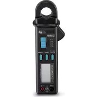
TESTFOX CC-1 - Multimeter Phoenix Contact - Free user manual and instructions
Find the device manual for free TESTFOX CC-1 Phoenix Contact in PDF.


| Product type | Digital clamp multimeter |
| Brand and model | Phoenix Contact TESTFOX CC-1 |
| Dimensions (L x W x H) | 192 x 66 x 27 mm |
| Weight | 205 g |
| Power supply | 2 batteries 1.5 V type CIE LR03 (micro) |
| Display | LCD 3 3/4 digits, 3999 counts, 13 mm height |
| Main functions | AC/DC voltage measurement, AC/DC current measurement, resistance, continuity test with buzzer, True RMS, HOLD/MAX function, zero adjustment (ZERO) |
| DC voltage ranges | 400 mV to 600 V, accuracy ±0.5% + 2 to 5 digits |
| AC voltage ranges | 400 mV to 600 V, accuracy ±1.5% + 5 digits, True RMS |
| DC current ranges | 0 to 300 A DC, accuracy ±2.5% + 2 digits |
| AC current ranges | 0 to 300 A AC, accuracy ±2.0% to 4.0% + digits, True RMS |
| Resistance ranges | 400 Ω to 40 MΩ, accuracy ±0.9% to 2.5% + digits |
| Continuity check | Buzzer activated for resistance < 50 Ω to 300 Ω |
| Electrical safety | Overvoltage category II 600 V, III 300 V, double insulation (class II), IP30 |
| Maximum jaw opening | 25 mm (conductor diameter max 22 mm) |
| Auto power off | After approx. 30 minutes |
| Operating temperature | 0 °C to 50 °C (depending on humidity) |
| Maintenance and cleaning | Clean with a clean, dry cloth. Do not use solvents. Replace batteries if the battery symbol appears. Remove batteries for prolonged storage. |
| Spare parts and repairability | Safety test leads included (1.4 m). Battery replacement possible. Calibration recommended annually. |
| General information | User manual provided. Use in dry environment only. Maximum altitude 2000 m. |
Frequently Asked Questions - TESTFOX CC-1 Phoenix Contact
User questions about TESTFOX CC-1 Phoenix Contact
0 question about this device. Answer the ones you know or ask your own.
Ask a new question about this device
Download the instructions for your Multimeter in PDF format for free! Find your manual TESTFOX CC-1 - Phoenix Contact and take your electronic device back in hand. On this page are published all the documents necessary for the use of your device. TESTFOX CC-1 by Phoenix Contact.
USER MANUAL TESTFOX CC-1 Phoenix Contact
Fig. 6: AC/ DC current measurement
Fig. 7: Battery replacement
Fig. 7: Remplacement des piles
Fig. 7: Cambio de pila
TRUE RMS Digital Current Clamp Multimeter for -alternating-currentmeasurement
- AC-voltage measurement
- DC-current measurement
- resistance measurement
- continuity testing
Contents:
- Notes for user
- Notes on safety
- Scope of delivery
- Description of unit
- General data
- Ambient conditions
- Electrical data
- Measuring with the TESTFOX CC-1
- Maintenance
- Technical data of the measuring accessories
11.Environmentalnote
1. Notes for user
This Operating Manual is intended for:
- qualified electricians, competent persons and
- electrotechnically trained persons.
The TESTFOX CC-1 is designed for measurements in dry surroundings and must not be used in circuits with rated voltages higher than 600 V (for more details, see section 6 "Ambient conditions").
The following symbols are used in the Operating Manual and on the TESTFOX CC-1 itself:

Application around and removal from HAZARDOUS LIVE conductors is permitted.

This symbol indicates an electrical hazard.

This symbol indicates sources of danger when using the TESTFOX CC-1 (see documentation).

This symbol on the TESTFOX CC-1 indicates that the unit is protection insulated (safety class II).

This symbol appears in the display for a discharged battery

This symbol indicates the continuity-testing application. The buzzer provides an audible signal.

DC-voltage or current

AC-current or voltage

Earth (voltage to earth)
Note
After unmark the adhesive label „Warnung...“ (on battery compartment lid) the English text appears.
2. Safety note
The instrument is built and tested in accordance with
DIN VDE 0411 part 1/ EN 61010-1
DIN VDE 0411 part 2-032/ EN 61010-2-032
DIN VDE 0411 part 2-033/ EN 61010-2-033
DIN VDE 0411 part 031/ EN 61010-031
and has left the factory in perfectly safe technical condition.
To maintain this condition and ensure safe operation of the multimeter, the user must observe the notes and warnings given in these instructions at all times. Improper handling and non-observance of the warnings might involve severe injuries or danger to life.

WARNING! Be extremely careful when working with bare conductors or main line carrier! Contact with live conductors will cause an electric shock!

The unit may be used only in power circuits within the over-voltage category II with a conductor for 600 V max. to earth, or within overvoltage category III with a conductor for 300 V against ground.
Only use suitable measuring leads for this. With measurements within measurement category III, the projecting conductive part of a contact tip of the measuring leads must not be longer than 4 mm.
Prior to carrying out measurements within measurement category III, the push-on caps provided with the set and marked with CAT III and CAT IV must be pushed onto the contact tips. The purpose of this measure is user protection.
Remember that work on electrical components of all kinds is dangerous. Even low voltages of 30 V AC and 60 V DC may be dangerous to human life.

Before starting the multimeter up, always check it as well as all cables and wires for signs of damage.
Should it appear that safe operation of the multimeter is no longer possible, it should be shut down immediately and secured to prevent it being switched on accidentally.
It may be assumed that safe operation is no longer possible:
- if the instrument or the measuring leads show visible signs of damage, or
- if the multimeter no longer functions, or
- after long periods of storage under unfavourable conditions, or
- after being subjected to rough transport,
- if the device or the measuring lead are exposed to moisture.

In order to avoid danger,
- do not touch the bare prod tips of the measuring leads,
- insert the measurement leads in the appropriately designated measuring sockets on the multimeter
3. Scope of delivery
The following items make up the standard TESTFOX CC-1 package:
3.1 One digital multimeter
3.2 One safety measuring leads (black)(L = 1.4 m)
3.3 One safety measuring leads (red) L = 1.4 ~m
3.4 One compact protection case
3.5 Two 1.5 V micro-batteries (installed in the multimeter when supplied)
3.6 One Operating Manual
Note on consumable parts:
- The TESTFOX CC-1 is supplied by two 1.5 V micro-batteries (2 x 1.5 V IEC LR 03)
- The above mentioned safety leads (tested spare part) are approved in accordance with CAT III 1000 V and for a current up 10 A.
4. Description of tester unit
The TESTFOX CC-1 is a digital current clamp multimeter with a measuring head fitted with a Hall sensor.
See fig. 1: Front panel
The display and operating elements shown in fig. 1 are as follows:
① Housing
② Sliding switch for selecting the required functions.
- OFF
- AC-voltage measurement (AC) and DC-voltage measurement (DC) These functions alternate when the function button marked with AC/DC is pressed. The digital display ③ indicates the current function.
- AC-current measurement (AC) and DC-current measurement (DC) These functions alternate when the function button marked with AC/DC is pressed. The digital display ③ indicates the current function.
- Resistance measurement and continuity measurement with buzzer These functions alternate when the function button marked with / is pressed. The digital display ③ indicates the current function.
3 Digital display (liquid-crystal type) with following indications:
- measurement reading with max. indication 3999
-polarityindication
-decimalpoint
- symbol for discharged battery
- type of voltage selected (AC or DC voltage)
- type of current selected (AC or DC current)
- the measurement value retained (hold function) or the automatically retained peak measurement value (MAX function)
- the measurement function selected by indication of the extended/non-extended measurement units of current and resistance
- selected continuity test with buzzer.
4 Function button AC/DC - Ω/ ..... The digital display ③ shows "DC", "AC", "Ω", ".....".
- Forselection between measurement of DC voltage/current or AC voltage/current or
- Resistance measurement and continuity test.
5 HOLD/MAX button (hold function and automatic peak-value storage)
- The first press of the button causes the currently indicated measurement value to be held (indicated by "HOLD" in the digital display ③, no updating of measurement value).
- The second press of the button leads to continuous measurement.
- Pressing the button (for 2 sec.) during switch-on initiates the peak-value storage (MAX) function. A second press of the button does not lead to continuous measurement.
- The first press of the button causes the peak value during the switched-on measuring time to be stored (indicated by "MAX" in the digital display ③). For all ranges except continuity test. Switch back (continuous measurement) by pressing MAX button (2 sec.).
- The function is switched off by pressing the OFF button.
6 ZERO button (zero setting button) for zero adjustment in current measurement. Can also be used for all ranges for differential measurement (zero setting possible for any value). Indicated by "REL" in the digital display.
7 COM socket: joint socket for voltage and resistance measurements and continuity test, marked black
8 ∀Ω socket (positive): joint socket for voltage and resistance measurements and continuity test, marked red
9 Opening lever, for opening and closing the current prongs
10 Prong guard, protects user from accidental contact with conductor
⑪ Measurement prongs, for inserting and gripping the single conductor containing AC current.
5. General data
5.1 General data on multimeter
5.1.1 The digital display is designed as a 3 3/4 digit liquid-crystal indicator with 13 mm digit height and decimal point. The highest value displayed is 3999.
5.1.2 The polarity indication ③ functions automatically. Contrary to the measurement-wire definition, only one pole is indicated as “-”.
5.1.3 The range overload will be displayed with "OL" or "-OL" and sometimes with an acoustic signal.
Attention: no display or warning by complete overload.
5.1.4 The nominal measuring rate of the digital display of the TESTFOX CC-1 is approx. 2 measurements per second.
5.1.5 The TESTFOX CC-1 switches off automatically after approx. 30 minutes. It can only be switched on again by means of the switch. The buzzer sounds to signal that the unit has switched off automatically.
5.1.6 Temperature coefficient of measurement value for voltage and resistance measurements: 0.15 x (stated measurement accuracy) °C < 18 °C or > 28 °C with reference to the value at the reference temperature of 23 °C.
5.1.7 Temperature coefficient of measurement value for current measurements:
0.2 x (stated measurement accuracy) °C < 20 °C or > 26 °C with reference to the value at the reference temperature of 23 °C.
5.1.8 The TESTFOX CC-1 is supplied by 2 1.5 V batteries (IEC LR03/ "Micro").
5.1.9 When the battery voltage drops under the intended operating voltage of the TESTFOX CC-1, a battery symbol appears in the display.
5.1.10 The service life of the battery is approx. 60 hours (alkali battery).
5.1.11 Dimensions of unit (length x width x height) = 192 x 66 x 27 mm.
Weight of unit: 205 g
5.1.12 The safety measuring leads and measurement tips supplied are specially suited to the rated voltage of the TESTFOX CC-1. The measuring tips can be protected by caps.
5.1.13 Widest prong opening: 25 mm
5.1.14 Largest wire diameter: 22 mm
6. Ambient conditions
- The TESTFOX CC-1 is designed only for measuring in dry surroundings.
- Maximum barometric height during measurement: 2000 m
- Overvoltage category / set-up category: IEC 60664-1/IEC 61010-1 → 300 V category III, 600 V category II,
- Degree of contamination: 2
- Protection Class: IP 30 (DIN VDE 0470-1 IEC/ EN 60529)
IP 30 means: Protection against access to dangerous parts and protection against solid impurities of a diameter >2.5 mm, (3 - first index). No protection against water, (0 - second index).
- Operating temperature and relative humidity for voltage and resistance measurements:
At operating temperature of 0 °C to 30 °C: relative humidity under 80% At operating temperature of 30 °C to 40 °C: relative humidity under 75%
At operating temperature of 40 °C to 50 °C: relative humidity under 45%
- Operating temperature and relative humidity for current measurements: At operating temperature of 0 °C to 30 °C: relative humidity under 80% At operating temperature of 30 °C to 40 °C: relative humidity under 75%
- The TESTFOX CC-1 can be stored at temperatures from - 20 °C to + 60 °C. The batteries must be removed from the unit.
7. Electrical data
Note: The measurement accuracy is stated as the sum of
- a relative proportion of the measurement value and
- a number of digits (i.e. numerical steps of the last place).
This measurement accuracy applies for a temperature of 23^ ± 5^ ( 23^ ± 3^ for current measurement) and a maximum relative humidity of 80% .
The TESTFOX CC-1 has an automatic switch-over of measurement range. Previous setting is therefore not required.
7.1 DC voltage range
The input resistance is ≥ 10 M .
| Measuring range | Resolution | Measurement accuracy | Overload protection |
| 400,0 mV | 100 μV | ± (0,5 % of reading + 5 digits) | 600 V_eff 600 V DC voltage |
| 4,000 V | 1 mV | ± (0,5 % of reading + 2 digits) | 600 V_eff 600 V DC voltage |
| 40,00 V | 10 mV | ± (0,5 % of reading + 2 digits) | 600 V_eff 600 V DC voltage |
| 400,0 V | 100 mV | ± (0,5 % of reading + 2 digits) | 600 V_eff 600 V DC voltage |
| 600 V | 1 V | ± (0,5 % of reading + 2 digits) | 600 V_eff 600 V DC voltage |
7.2 AC voltage range
The input resistance is ≥ 10 M parallel 100 pF. The measuring value is gained and indicated as effective value (True RMS, AC coupling). Its calibration is adapted for a sinusoidal curve form. With deviations from this form, the display value becomes less accurate. The additional error for the following crest factors is as follows:
crest factor of 1.4 to 2.0: additional error ± 1.0%
crest factor of 2.0 to 2.5: additional error ± 2.5%
crest factor of 2.5 to 3.0: additional error ± 4.0%
| Measuring range Resolution | Measurement accuracy | Overload protection |
| 400,0 mV 100 μV | ± (2,0 % of reading + 5 digits)*in frequency range 50 Hz - 60 Hz | 600 V_eff 600 V DC voltage |
| 4,000 V 1 mV | ± (1,5 % of reading + 5 digits)in frequency range 40 Hz - 300 Hz | 600 V_eff 600 V DC voltage |
| 40,00 V 10 mV | ± (1,5 % of reading + 5 digits)in frequency range 40 Hz - 500 Hz | 600 V_eff 600 V DC voltage |
| 400,0 V 100 mV | ± (1,5 % of reading + 5 digits)in frequency range 40 Hz - 500 Hz | 600 V_eff 600 V DC voltage |
| 600 V 1 V | ± (1,5 % of reading + 5 digits)in frequency range 40 Hz - 500 Hz | 600 V_eff 600 V DC voltage |
* When input is opened, fluctuating up to 30 digits; measuring range ≥ 1 mV
7.3 Resistance range
No-load voltage approx. 0.3 V, max. test current 0.2 mA
| Measuring range Resolution | Measurement accuracy | Overload protection |
| 400 Ω 100 mΩ | ± (1,2 % of reading + 6 digits)*1 | 600 Veff600 V DC voltage |
| 4,000 kΩ 1 Ω | ± (0,9 % of reading + 3 digit)*2 | 600 Veff600 V DC voltage |
| 40,00 kΩ 10 Ω | ± (0,9 % of reading + 3 digit)*2 | 600 Veff600 V DC voltage |
| 400,0 kΩ 100 Ω | ± (1,2 % of reading + 3 digit)*2 | 600 Veff600 V DC voltage |
| 4,000 MΩ 1 kΩ | ± (1,2 % of reading + 3 digit)*2 | 600 Veff600 V DC voltage |
| 40,00 MΩ 10 kΩ | ± (2,5 % of reading + 5 digit)*1 *3 | 600 Veff600 V DC voltage |
^1 in end area of display only, + 6 digits
^2 in end area of display only, + 3 digits
^*3 maximum start-up time until display appears, 20 sec.
7.4 Continuity test
No-load voltage approx. 3 V, max. test current 0.1 mA
The built-in buzzer sounds when resistance is less than 50 Ω - 300 Ω.
7.5 DC current ranges
Measurement accuracy at a temperature of 23 °C ± 3 °C
| Measuring range Resolution | Measurement accuracy | Overload protection | |
| 40.0 A 10 mA ± (2.5 % of reading + 2 digit) | 400 A | ||
| 40.0 - 200.0 A | 100 mA | ± (2.5 % of reading + 2 digit) | 400 A |
| 200.0 - 300.0 A | 100 mA | ± (3.0 % of reading + 2 digit) | 400 A |
7.6 AC current ranges
Measurement accuracy at a temperature of 23 ^ ± 3 ^ . The measuring value is gained and indicated as effective value (True RMS, AC coupling). Its calibration is adapted for a sinusoidal curve form. With deviations from this form, the display value becomes less accurate. The additional error for the following crest factors is as follows:
crest factor of 1.4 to 2.0: additional error ± 1.0%
crest factor of 2.0 to 2.5: additional error ± 2.5%
crest factor of 2.5 to 3.0: additional error ± 4.0%
| Measuring range Resolution | Measurement accuracy | Overload protection | |
| 0 - 4.0 A | 10 mA | ± (2.0 % of reading + 5 digit)^* for frequencies 50 - 60 Hz ± (3.0 % of reading + 7 digit)^* for frequencies 40 - 1 kHz | 400 A |
| 4.00 - 40.00 A | 10 mA | ± (2.5 % of reading + 3 digit)^* for frequencies 50 Hz - 60 Hz ± (3.5 % of reading + 5 digit)^* for frequencies 40 Hz - 1 kHz | 400 A |
| 40.0 - 200.0 A 100 mA | ± (2.5 % of reading + 3 digit)for frequencies 50 Hz - 60 Hz± (3.5 % of reading + 5 digit)for frequencies 40 Hz - 1 kHz | 400 A |
| 200.0 - 300.0 A 100 mA | ± (4.0 % of reading + 3 digit)for frequencies 50 Hz - 60 Hz± (6.0 % of reading + 5 digit)for frequencies 40 Hz - 1 kHz | 400 A |
* measuring range ≥ 0,1 A
7.7 Maximum HOLD
The measuring accuracy of the MAX-Hold display is the stated measuring accuracy in % + 10 digits for the next measuring range. When passing to the measuring range after next, the error increases to + 20 digits etc. (Example: starting figure 100 mV - 120 V = + 30 digits). When measuring resistance, a MAX hold indication is only possible in the range from 400 Ω to 400 kΩ.
8. Measuring with the TESTFOX CC-1
8.1 Preparation for measuring
Store and use the TESTFOX CC-1 only under the correct temperature conditions stated. Always avoid longer exposure to sunlight.
- Check the rated voltage and current stated on the safety measuring leads with tips. The rated voltage and current of the safety measuring leads and tips comply with the TESTFOX CC-1.
- Check the insulation of the measuring leads and tips. If the insulation is damaged, replace the safety measuring leads immediately.
- Check the continuity of the safety measuring leads. If the leads is disconnected at any point, remove it immediately.
- Before selecting another function with the sliding switch ② or the function button ④, the safety measuring leads and tips must be disconnected from the measuring point.
- Strong sources of interference close to the TESTFOX CC-1 may produce unstable readings and measurement errors.
8.2 Voltage measurement

Always observe the maximum voltage to earth potential! Electrical hazard!
The maximum voltage which may be applied to the sockets
- COM socket, black ⑦,
-
V-Ω socket (positive) 8 for voltage and resistance measurements and continuity testing (marked red)
of the TESTFOX CC-1 against ground, amounts to 600 V. -
Select the desired function with the sliding switch ② and the function button ④ of the TESTFOX CC-1.
- Contact the black safety measuring lead with the COM-socket ⑦ (black).
- Contact the red safety measuring lead with the V-Ω socket ⑧ (red).
- Bring the black and red measuring tips into contact with the measurement points. Read the measured value on the digital display ③.
Note:
- In small voltage measuring ranges, the zero-volt indication does not appear (due to interference) when the safety measuring leads are open. Make sure that the TESTFOX CC-1 is fully functional by short-circuiting the measuring tips.
See fig. 2: DC-voltage measurement
See fig. 3: AC-voltage measurement
8.3 Resistance measurement
- Select the desired function with the sliding switch ② and the function button ④ of the TESTFOX CC-1.
- Contact the black safety measuring lead with the COM-socket ⑦ (black).
- Contact the red safety measuring lead with the V-Ω socket ⑧ (red).
- Bring the black and red measuring tips into contact with the measurement points. Read the measured value on the digital display ③.
Note:
- To obtain a correct measurement, ensure that no voltage is applied to the measuring point.
- With small resistances, the measuring result can be improved by measuring the resistance of the safety measuring leads beforehand by short-circuiting the measuring tips and subtracting the reading obtained from the resistance measured.
See fig. 4: Resistance measurement
8.4 Continuity testing with buzzer
- Select the area marked with the buzzer symbol with the sliding switch ② and the function button ④ of the TESTFOX CC-1.
- Contact the black safety measuring lead with the COM-socket ⑦ (black).
- Contact the red safety measuring lead with the V-Ω socket 8 (red).
- Bring the black and red measuring tips into contact with the measurement points. If the resistance between the measurement points is less than 50 Ω, the buzzer incorporated in the TESTFOX CC-1 sounds.
See fig. 5: Continuity testing with buzzer
8.5 Current measurement
8.5.1 Preparation for measurement
Store and use the TESTFOX CC-1 only under the correct temperature conditions stated. Always avoid long exposure to sunlight.
- Strong sources of interference close to the TESTFOX CC-1 may produce unstable readings and measurement errors.

Do not apply voltage to the output contacts of the TESTFOX CC-1. If necessary, remove the safety measuring leads connected. When measuring DC current, observe correct polarity.
8.5.2 Current measurement
- Select the desired measuring function with the sliding switch ② and the function button ④.
- Press the "ZERO" button to set the TESTFOX CC-1 to the starting point.
- Operate the opening lever ⑨. Grip the single wire containing the current to be measured with the prongs of the TESTFOX CC-1.
- Read the value in the digital display ③.
See fig. 6: AC/ DC current measurement
9. Maintenance

Before opening the TESTFOX CC-1, ensure that it is not connected to a source of voltage! Electrical hazard!
Any work required on the TESTFOX CC-1 when it is under voltage must be done only by a qualified electrician. Special steps must be taken to prevent accidents.
Before opening the TESTFOX CC-1, remove it from all sources of voltage as follows:
- Remove first the black and the red measuring tip from the measurement object.
- Then remove the black and red safety measuring leads from the TESTFOX CC-1.
- Move the sliding switch to the position "OFF".
9.1 Making the unit safe
Under certain circumstances, the safety of the TESTFOX CC-1 can no longer be guaranteed. This may be the case if:
- there are visible signs of damage on the unit,
- errors occur in measurements,
- the unit has been stored for a long period of time under the wrong conditions, and
- if the unit has been subjected to rough handling during transport.
In these cases, the TESTFOX CC-1 must be switched off immediately, removed from the measuring points and secured to prevent it from being used again.
9.2 Cleaning
Clean the outside of the unit with a clean dry cloth. (Exception: any type of special cleaning cloth). Never use solvents or abrasives to clean the clamp meter. Ensure that the battery compartment and the battery contacts have not been contaminated by electrolyte leakage. If any electrolyte or white deposits are seen in the battery compartment or battery housing, remove these with a dry cloth.
9.3 Battery replacement

Before opening the TESTFOX CC-1, ensure that it is not connected to a source of voltage! Electrical hazard!
The TESTFOX CC-1 is powered by two 1.5 V batteries. The batteries must be replaced (see fig. 8) when the battery symbol appears in the display 3.
To replace the batteries, proceed as follows:
- Remove the black and red measuring tips from the measurement circuit.
- Remove the black and red safety measuring leads from the TESTFOX CC-1.
- Lay the TESTFOX CC-1 on its front and unscrew the screw on the cover of the battery compartment.
- Push the cover of the battery compartment to the side out of its guide.
- Remove the discharged batteries from the battery holder.
- Insert the new batteries into the battery holder. Make sure that they are connected to the correct battery poles.
- Push the cover of the battery compartment into its correct position and replace the screw.
See fig. 7: Replacing the batteries.

Remember the environment! Do not dispose of used batteries with domestic waste. Dispose of them at a battery-collection point or as toxic waste. Your local authority will give you the information you need.
9.4 Calibration
To maintain the specified precision of the measurement results, the instrument must be recalibrated at regular intervals by our factory service. We recommend a recalibration interval of one year.
10. Technical data of the measuring accessories
- Standard: EN 61010-031,
- Maximum rated voltage to earth ( ± ) and measuring category:
With push-on caps: 1000 V CAT III, 600 V CAT IV,
Without push-on caps: 1000 V CAT II,
- Maximum rated current: 10 A,
- Protective class II (回), continuous double or reinforced insulation,
- Contamination class: 2,
- Length: 1.4 m, AWG 18,
-Environmentalconditions:
Maximum barometric elevation for making measurements: 2000 m,
Temperatures: 0 °C to + 50 °C, humidity 50 % to 80 %
- Only use the test leads if in perfect condition and according to this manual, since the protection provided could otherwise be impaired.
-Throwthetest leads out if the insulation is damaged or if there is a break in the cable/ plug. - Do not touch the bare contact tips of the test leads. Only grab the area appropriate for hands!
- Insert the angled terminals in the testing or measuring device.
11.Environmentalnote
At the end of the product's useful life, please dispose of the device at collection points provided in your community.
- Contents:
- Notes for user
- Note
- Safety note
- Scope of delivery
- Description of tester unit
- General data
- General data on multimeter
- Ambient conditions
- Electrical data
- DC voltage range
- AC voltage range
- Resistance range
- Continuity test
- DC current ranges
- AC current ranges
- Maximum HOLD
- Measuring with the TESTFOX CC-1
- Preparation for measuring
- Voltage measurement
- Always observe the maximum voltage to earth potential! Electrical hazard!
- Note:
- Resistance measurement
- See fig. 4: Resistance measurement
- Continuity testing with buzzer
- Current measurement
- Current measurement
- Maintenance
- Making the unit safe
- Cleaning
- Battery replacement
- Calibration
- Technical data of the measuring accessories
- 11.Environmentalnote
Brand : Phoenix Contact
Model : TESTFOX CC-1
Category : Multimeter