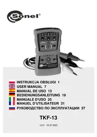
TKF-13 - Electrical tester Sonel - Free user manual and instructions
Find the device manual for free TKF-13 Sonel in PDF.


| Product type | Phase sequence tester / Electrical tester |
| Brand | Sonel |
| Model | TKF-13 |
| Dimensions | 130 x 72 x 31 mm |
| Weight | 150 g approx. |
| Power supply | Alkaline battery 6LR61 (9 V) |
| Operating voltage range | 120 to 760 V AC between phases |
| Frequency range | 2 to 70 Hz |
| Measurement category | III 600 V (EN 61010-1) |
| Protection rating | IP42 |
| Operating temperature | -10 to 45 °C |
| Storage temperature | -20 to 60 °C |
| Automatic shutdown | Approximately 5 minutes |
| Low battery indicator | Flashing LED at ~10% charge |
| Phase rotation direction test | Yes (R and L LEDs) |
| Motor rotation direction test (wired) | Yes, by manual rotation of the shaft |
| Motor rotation direction test (wireless) | Yes, by placing the device 2–3 cm from the running motor |
| Cleaning and maintenance | Soft damp cloth with common detergents; no solvents |
| Safety | Double insulation, compliant with EN 61010-1 |
| Manufacturer | SONEL S.A., Poland (customer service: +48 74 884 10 53) |
| Repairs | Only by the manufacturer |
Frequently Asked Questions - TKF-13 Sonel
User questions about TKF-13 Sonel
0 question about this device. Answer the ones you know or ask your own.
Ask a new question about this device
Download the instructions for your Electrical tester in PDF format for free! Find your manual TKF-13 - Sonel and take your electronic device back in hand. On this page are published all the documents necessary for the use of your device. TKF-13 by Sonel.
USER MANUAL TKF-13 Sonel
INSTRUKCJA OBSŁUGI 1
USER MANUAL 7
MANUAL DE USO 13

• Naciskając

1 Safety 8
2 Phase rotation direction test....9
3 Motor shaft rotation direction (using leads)....9
4 Motor shaft rotation direction (connectionless)....10
5 Power supply turn-off....11
6 Battery charge signalling....11
7 Replacement of batteries....11
8 Cleaning and maintenance ....11
9 Storage....11
10 Dismantling and utilization....11
11 Technical data....12
12 Manufacturer....12
We appreciate your having purchased our phase sequence and motor rotation direction tester. The TKF-13 tester is a modern high-quality, simple and safe device. However it is recommended to get acquainted with the present manual in order to avoid measuring errors and prevent possible problems related to operation of the meter.

The manufacturer reserves the right to modify the appearance, equipment and technical data of the device.
1 Safety
The TKF-13 tester complies with the safety requirements specified in the norm EN 61010-1. In order to protect yourself and the device do observe the rules described in the present manual.

Warning:
- Do not perform tests in a humid environment, which contains explosive or inflammable gases (materials), water vapour or dust.
- Having carried the device from a cold environment to a warm one, wait 0.5 hour before you proceed to perform measurements for the purpose of acclimatisation, if necessary wipe out the condensed water vapour.
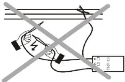
- During measurements do not touch the metal parts of the socket, lead terminals, fastening elements, circuits, etc.
- Make sure you are properly insulated from the tested object.
- Do not perform measurements using an out-of-order device, whose casing or leads are damaged (broken, cracked, deformed, contaminated, etc.).
- The TKF-13 tester may be operated exclusively by qualified personnel who are properly authorised to perform work on electric installations. Should the device be operated by unauthorised personnel, the device may be damaged and there may be a serious danger for the operator.
- The tester may be connected to the mains solely by means of dedicated leads provided by the manufacturer. Solely such leads guarantee compliance with safety regulations.
- If phase-to-phase voltage exceeding 760 V AC will be connected to the device, the tester may be damaged and there may be a risk for the operator.
- If the device will be used for any other purpose than those specified in the present operating manual, the tester may be damaged and there may be a serious risk for the operator.
2 Phase rotation direction test
- Press to turn the tester on. The green diode should go ON signalling that the device is ready for operation.
- Connect measurement probes to the TKF-13 tester.
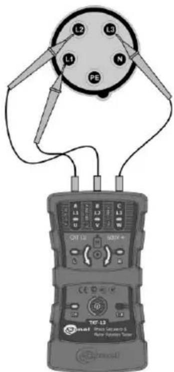
- Connect measurement probes to the points where there is the expected three-phase voltage (see the illustration below).
- If the phases at the given measurement points are compliant with the L1, L2, L3 description, the R diode of the tester will go on; otherwise the L diode will go on.
- The light of the given neon lamp (L1, L2, L3) signalises a voltage exceeding 100 V between the corresponding probe and one of the remaining probes.

Incorrect indications of the tester may be caused by one of the following:
- connection of two probes to one phase,
- connection of one of the probes to the neutral lead,
- lack of connection of one of the probes to the mains.
3 Motor shaft rotation direction (using leads)
- Disconnect the motor from the mains.
- Press to turn the tester on. The green diode should go ON signalling that the device is ready for operation.
- Connect measurement probes to the TKF-13 tester.
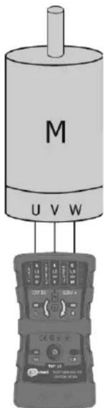
- Connect measurement probes to the tested motor (see the adjacent illustration).
- Rotate the motor shaft energetically in the desired direction.
- The light of the R diode means the connection to the U, V and W motor terminals of phases L1, L2 and L3, respectively, will cause rotation of the motor in the direction the shaft spun during the test.
- The light of the L diode means the connection to the U, V and W motor terminals of phases L1, L2 and L3, respectively, will cause rotation of the motor in the opposite direction to the direction the shaft spun during the test.
- Make sure the shaft rotates in the desired direction once the motor has been connected to the power supply source performing a phase sequence test (see Chapter 2).
4 Motor shaft rotation direction (connectionless)
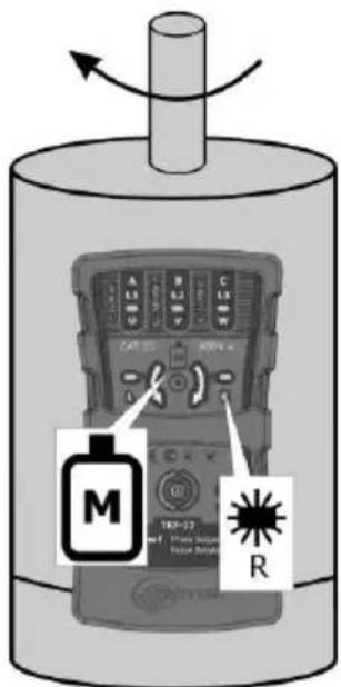

- Press to turn the tester on. The green diode should go ON signalling that the device is ready for operation.
- Put the rear part of the TKF-13 tester to a working motor along its axis (the position of the axis in accordance with the adjacent illustration). The distance between the tester and the motor should not exceed 2-3 cm.
- The light of the R diode means the motor shaft spins clockwise. The light of the L diode means the motor shaft spins anticlockwise.
- Lack of indications (diodes L and R are off) may mean the motor is not working or the signal is too weak.

- In case of certain single-phase inductive motors, indications may be hindered.
- The device has not been designed for the purpose of tests of single-phase commutator motors.
- The device has not been designed for the purpose of tests of motors powered through electronic power converters (inverters).
Below there is a diagram illustrating the minimum motor diameter for the given revolution and the frequency of the mains at which the indications of the tester are reliable.
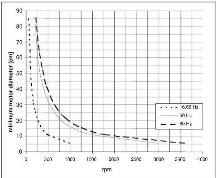
line
| rpm | 16.66 Hz | 50 Hz | 60 Hz | | ---- | -------- | ----- | ----- | | 0 | 85 | 85 | 85 | | 500 | 30 | 40 | 50 | | 1000 | 10 | 20 | 30 | | 1500 | 5 | 15 | 20 | | 2000 | 5 | 10 | 15 | | 2500 | 5 | 8 | 12 | | 3000 | 5 | 7 | 10 | | 3500 | 5 | 6 | 8 | | 4000 | 5 | 5 | 6 |5 Power supply turn-off
If within five minutes the L or R diode does not go on, the tester is automatically turned off, and the ON diode goes off.

It is not possible to turn the power supply off manually.
6 Battery charge signalling
- When the tester detects the battery charge amounts to 10% of its full charge, the battery charge diode starts to blink once a second. Measurements are still possible.
- If the battery is discharged, then the battery charge diode is it continuously and it is impossible to perform measurements. It is necessary to replace batteries. If the battery is not replaced, then after five minutes the tester will be automatically turned off.
7 Replacement of batteries
- Disconnect the measurement probes from the mains.
- Remove the elastic protection from the casing.
- Unscrew the rear part of the casing and remove it.
- Remove the battery from the tester and disconnect it.
- Connect a new battery, screw the rear flap and place the elastic protection upon the casing.
8 Cleaning and maintenance

NOTE!
Use solely the maintenance techniques specified by the manufacturer in this use manual.
The tester may be cleaned with a soft, damp cloth using all-purpose detergents.
Do not use any solvents or cleaning agents which might scratch the casing (powders, pastes, etc.).
The electronic system of the meter does not require maintenance..
9 Storage
In the case of storage of the device, the following recommendations must be observed:
• Make sure the tester is dry.
- Should the tester be stored for a prolonged period of time, the battery will be removed.
10 Dismantling and utilization
Worn-out electric and electronic equipment should be gathered selectively, i.e. it must not be placed with waste of another kind.
Worn-out electronic equipment should be sent to a collection point in accordance with the law of worn-out electric and electronic equipment.
Before the equipment is sent to a collection point, do not dismantle any elements.
Observe the local regulations concerning disposal of packages, worn-out batteries and rechargeable batteries.
11 Technical data
a) Type of insulation in accordance with EN 61010-1.....double
b) Measurement category in accordance with EN 61010-1 ....III 600 V
c) Ingress protection in accordance with EN 60529 IP42
d) Frequency range 2 ÷ 70 Hz
e) Nominal phase-to-phase voltage range 127 ÷ 690 V AC
f) Phase-to-phase working voltage range 120 ÷ 760 V AC
g) Motor voltage range.... 1 ÷ 760 V AC
h) Measurement current (per each phase) ....<3.5 mA
i) Working temperature....-10÷45°C
j) Storage temperature....-20 ÷ 60°C
k) Battery charge diode blinking rate......approximately 1 s
I) Time before automatic turn-off......approximately 5 min
m) Tester power supply ....alkaline battery 6LR61 (9 V)
n) Dimensions.... 130 x 72 x 31 mm
o) Mass of the tester (with battery, without leads)......ca. 150 g

The device does not have the character of a standard and therefore is not subject to calibration. The proper form of control for this type of instrument is checking.
12 Manufacturer
The manufacturer of the device and provider of guarantee and post-guarantee service:
SONEL S.A.
Wokulskiego 11
58-100 Świdnica
Poland
tel. +48 74 884 10 53 (Customer Service)
e-mail: customerservice@sonel.com
web page: www.sonel.com

NOTE!
Service repairs must be performed only by the manufacturer.
MANUAL DE USO
• Durch Drücken von


Premendo

- Safety
- Warning:
- Phase rotation direction test
- Motor shaft rotation direction (using leads)
- Motor shaft rotation direction (connectionless)
- Power supply turn-off
- Battery charge signalling
- Replacement of batteries
- Cleaning and maintenance
- NOTE!
- Storage
- Dismantling and utilization
- Technical data
- Manufacturer
- MANUAL DE USO
Brand : Sonel
Model : TKF-13
Category : Electrical tester