DTR 8510 - Measuring equipment CHAUVIN ARNOUX - Free user manual and instructions
Find the device manual for free DTR 8510 CHAUVIN ARNOUX in PDF.


User questions about DTR 8510 CHAUVIN ARNOUX
0 question about this device. Answer the ones you know or ask your own.
Ask a new question about this device
Download the instructions for your Measuring equipment in PDF format for free! Find your manual DTR 8510 - CHAUVIN ARNOUX and take your electronic device back in hand. On this page are published all the documents necessary for the use of your device. DTR 8510 by CHAUVIN ARNOUX.
USER MANUAL DTR 8510 CHAUVIN ARNOUX
1.1. RÉCEPTION DU COLIS
text_image
Format Date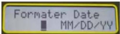
text_image
Formater Date ■ MM/DD/YYFigure 4-6
text_image
Activer OUI NONFigure 4-10
text_image
PRI :0019920 SEC :0007200Figure 4-13
REMARQUE :
text_image
Effacer MémoireFigure 4-18
text_image
Lire MémoireFigure 4-20
text_image
Circuit X: --- Circuit H:Figure 5-3

chemical
Electrical circuit diagram showing a transformer with primary and secondary windings labeled HR/HB, HB/HR, P, S, XR/XB, XB/XR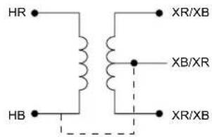
text_image
HR HB XR/XB XB/XR XR/XB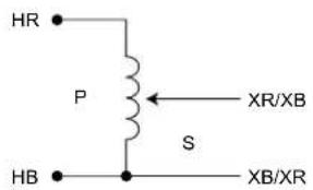
text_image
HR P S HB XR/XB XB/XRMesures - INCORRECTES
text_image
HB P S HR XR/XB XB/XR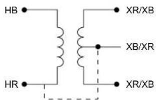
text_image
HB HR XR/XB XB/XR XR/XB6.2. BRANCHEMENTS POLyPHASéS
| N° de REF | - TRANSFORMATEUR - | TYPE XFMR | PHASE | ENROULEMENT HAUTE TENSION | ENROULEMENT BASSE TENSION | RAPPORT DE TRANSFORMATION | |
| ENROULEMENT HAUTE TENSION | ENROULEMENT BASSE TENSION | ||||||
| 1 | 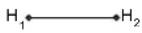 | 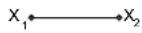 | 1 ∅ STD | 1 ∅ | H_1-H_2 | X_1-X_2 | _HV_X |
| 2 |  |  | Δ - Δ STD | A | H_1-H_3(A) | X_1-X_3(a) | _HV_X |
| B | H_2-H_1(B) | X_2-X_1(b) | |||||
| C | H_3-H_2(C) | X_3-X_2(c) | |||||
| 3 |  |  | Δ - Δ REV | A | H_1-H_3(A) | X_1-X_3(a) | _HV_X |
| B | H_2-H_1(B) | X_2-X_1(b) | |||||
| C | H_3-H_2(C) | X_3-X_2(c) | |||||
| 4 |  | 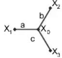 | Δ - Y STD | A | H_1-H_3(A) | X_1-X_0(a) | _H · [3]V_XV_X |
| B | H_2-H_1(B) | X_2-X_0(b) | |||||
| C | H_3-H_2(C) | X_3-X_0(c) | |||||
| 5 |  | 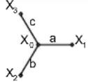 | Δ - Y REV | A | H_1-H_3(A) | X_1-X_0(a) | _H · [3]V_XV_X |
| B | H_2-H_1(B) | X_2-X_0(b) | |||||
| C | H_3-H_2(C) | X_3-X_0(c) | |||||
| 6 | 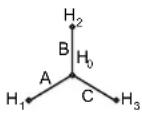 | 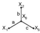 | Y - Y STD | A | H_1-H_0(A) | X_1-X_0(a) | _HV_X |
| B | H_2-H_0(B) | X_2-X_0(b) | |||||
| C | H_3-H_0(C) | X_3-X_0(c) | |||||
| 7 | 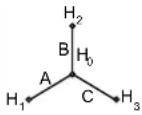 | 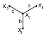 | Y - Y REV | A | H_1-H_0(A) | X_1-X_0(a) | _HV_X |
| B | H_2-H_0(B) | X_2-X_0(b) | |||||
| C | H_3-H_0(C) | X_3-X_0(c) | |||||
| 8 | 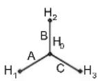 | 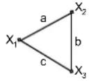 | Y - Δ STD | A | H_1-H_0(A) | X_1-X_2(a) | _HV_X · [3]3 |
| B | H_2-H_0(B) | X_2-X_3(b) | |||||
| C | H_3-H_0(C) | X_3-X_1(c) | |||||
| 9 | 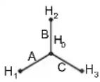 |  | Y - Δ REV | A | H_1-H_0(A) | X_1-X_2(a) | _HV_X · [3]3 |
| B | H_2-H_0(B) | X_2-X_3(b) | |||||
| C | H_3-H_0(C) | X_3-[3](c) | |||||
7.1. INSTALLATION DE DATAVIEW®

NE PAS BRANCHER L'APPAREIL A L'ORDINATEUR AVANT D'INSTALLER LE LOGICIEL ET LES PILOTES.
text_image
Setup English Financials Spanish Install Exit Select an option from the list below, then select the Install button. Options DataView Version 3.06.0009 Adobe Reader Dataview Update Hardware Upgrades Documents Description Installs the English version of DataView onto this computer. This version of DataView supports the following instruments: Ground Tester (Model 6470-B, 6471 and 6472) Megohemeter (Model 1060, 5060 and 5070) Micro-Ohmeter (Model 6240 and 6250) Power Mole (Model 8220) Power Quality Logger (Model PQL100 and PQL120) PowerPad (Model 3945 and 3945-B) PowerPad II (Model 6335) PowerPad Jr (Model 8230) Sentinel Data Logger Simple Logger II DTR Model 8510Figure 7-1
text_image
DataView - InstallShield Wizard Select Features Select the features setup will install Select the features you want to install, and deselect the features you do not want to install OTR Ground Integrity Mouse Ground Textiles Installation Textiles Magiohmometer MicroDiameter Power Quality Logger PowerPad PowerPad II (Model 8335) PowerPad Jr Sentinel Data Logger Simple Logger II Watermeter 8220 PDF (%Change) Description OTR support file 31.57 MB of space required on the C drive 172882.03MB of space available on the C drive < Back Next > CancelFigure 7-2
text_image
DataView - InstallShield Wizard Do not connect the AEMC USB Instrument (or cable) until after the installation of the drivers and the DataView software has finished. If the AEMC USB Instrument (or cable) is connected to the computer now then disconnect, it from the computer before proceeding. OKFigure 7-3

text_image
Connection Communications port DTR Model 0510 (SN 128511HKDV) Communication rate 115200 OK Cancel HelpFigure 7-4
text_image
FTP Control Panel - Untitled FTP Control Panel: Untitled FTP Control Panel: Untitled FTP Control Panel: Untitled FTP Control Panel: Untitled FTP Control Panel: Untitled FTP Control Panel: Untitled FTP Control Panel: Untitled FTP Control Panel: Untitled FTP Control Panel: Untitled FTP Control Panel: Untitled FTP Control Panel: Untitled FTP Control Panel: Untitled FTP Control Panel: Untitled FTP Control Panel: Untitled FTP Control Panel: Unt titled FTP Control Panel: Untitled FTP Control Panel: Untitled FTP Control Panel: Untitled FTP Control Panel: Untitled FTP Control Panel: Untitled FTP Control Panel: Untitled FTP Control Panel: Untitled FTP Control Panel: Untitled FTP Control Panel: Untitled FTP Control Panel: Untitled FTP Control Panel: Untitled FTP Control Panel: Untitled FTP Control Panel: Untitled FTP Control Panel: Untitled ftp10000000000000000000000000000000000000000000000000000000000000000000000000000000000000000000000000000 FTP Control Panel: Untitled FTP Control Panel: Untitled FTP Control Panel: Untitled FTP Control Panel: Untitled FTP Control Panel: Untitled FTP Control Panel: Untitled FTP Control Panel: Untitled FTP Control Panel: Untitled FTP Control Panel: Untitled FTP Control Panel: Untitled FTP Control Panel: Untitled FTP Control Panel: Untitled FTP Control Panel: Untitled FTP Control Panel: Untitled FP1234678888888888888888888888888888888888888888888888888888888888888888888888888888888888888888888888888888Figure 7-7
text_image
Date/Time Date 11/ 8/2010 OK Time 4:33:30 PM Cancel Synchronize with PC ClockFigure 7-9
text_image
Run Test Test Type VT / PT CT Test Mode Ratio Cont/Ratio Test Filter Fast Normal Slow Primary 13000 Secondary 120 Test Result Measurement Date: 11/8/2010 - 4:58:21 PM Object: 1 Test: 1 Test type: VT/PT Test mode: Ratio Filter: Normal Turn ratio: 115.05:1 Deviation: 0.04 % Excitation current: 0 mA Primary voltage: 13800 V Secondary voltage: 120 V Object: 1 Text 1 Start Save CloseFigure 7-10
Thank you for purchasing a digital transformer ratiometer DTR® 8510.
For best results from your instrument:
■ read these operating instructions carefully,
■ comply with the precautions for use.

WARNING, risk of DANGER! The operator must refer to these instructions whenever this danger symbol appears.

Equipment protected by double insulation.

Caution! Risk of electric shock. The voltage at the parts marked with this symbol may be dangerous.

Important instructions to read and understand completely.

Important information to acknowledge.

Battery.

Fuse.

USB socket.

Earth.

The CE marking indicates conformity with European directives, in particular LVD and EMC.

The rubbish bin with a line through it indicates that, in the European Union, the product must undergo selective disposal in compliance with Directive WEEE 2002/96/EC. This equipment must not be treated as household waste.
Definition of measurement categories:
■ Measurement category IV corresponds to measurements taken at the source of low-voltage installations.
Example: power feeders, counters and protection devices.
■ Measurement category III corresponds to measurements on building installations.
Example: distribution panel, circuit-breakers, machines or fixed industrial devices.
■ Measurement category II corresponds to measurements taken on circuits directly connected to low-voltage installations.
Example: power supply to electro-domestic devices and portable tools.
CONTENTS
1. PRECAUTIONS FOR USE......44
1.1. Receiving Your Shipment 44
2. PRODUCT FEATURES....45
2.1.Description....45
2.2. Control Features....46
2.3. Cable Identification 47
3. SPECIFICATIONS....48
3.1. DTR® 8510 Specifications .... 48
3.2. Battery Charger Specifications....49
4. DISPLAY FUNCTIONS 50
4.1. Program Flow 50
4.2.Top Level Menu 50
4.3. Configure Instrument....50
4.4. Recall Data....57
5. OPERATION 59
5.1.Power Up 59
5.2. Running a Test....59
5.3. Tips for Making Precise Ratio Measurements 63
5.4. Ratio Test - 1:1 64
6. CONNECTIONS....65
6.1. Connection Diagrams....65
6.2. Polyphase Connections 66
7. DATAVIEW® SOFTWARE....67
7.1. Installing DataView ^® 67
7.2. Opening the Control Panel....69
7.3. Using the Control Panel 70
7.4. Configuring the DTR® 8510....71
7.5. Running a Test....72
7.6. Downloading a Test....73
7.7. Saving the Measurement Records 74
7.8. Report Generation....74
8. MAINTENANCE....76
8.1. Charging the Batteries 76
8.2. Cleaning 77
8.3. Metrological check....78
8.4. Repair....78
9. APPENDIX: DISPLAYMESSAGES....79
10. WARRANTY 80
11. TO ORDER......81
11.1. Replacement parts 81
1. PRECAUTIONS FOR USE
These safety warnings are provided to ensure the safety of personnel and proper operation of the instrument.
This instrument is protected from accidental voltages of not more than 50 V with respect to earth. The guaranteed level of protection of this equipment may be compromised if used in a manner not specified by the manufacturer.
- Read the instruction manual completely and follow all safety information before attempting to use or service this instrument.
■ The Digital Transformer Ratiometer DTR510 is designed for use on de-energized ("dead") transformers only. Make sure the test sample is completely disconnected from AC power and is fully discharged.
■ Only qualified personnel should use the DTR\$510.
The DTR8510 must not be used in a manner in which any of its components (including test cables) are relied upon to provide protection from electric shock. No high voltage insulation/protection is provided by any component of the DTR® 8510. Always make sure the circuit is fully discharged before attaching any test cables.
■ Do not touch, adjust, or reposition test cables while the DTRs conducting a test.
■ Use caution on any apparatus: potentially high voltages and currents may be present and pose a shock hazard.
■ Safety is the responsibility of the user.
■ Only use the charging unit supplied with the instrument to recharge the battery.
■ Never open the instrument while it is connected to AC power or when test cables are connected to transformers, equipment, circuits, etc.
1.1. RECEIVING YOUR SHIPMENT
Upon receiving your shipment, make sure that the contents are consistent with the packing list. Notify your distributor of any missing items. If the equipment appears to be damaged, file a claim immediately with the carrier and notify your distributor at once, giving a detailed description of any damage. Save the damaged packing container to substantiate your claim.
2.1. DESCRIPTION
The Digital Transformer Ratiometer DTR ^® 8510 is a lightweight, rugged, portable instrument designed for onsite testing of power, potential and current transformers.
Operation of the DTR ^® 8510 is fully automatic. No user calibration, range selection, hand cranking or tedious balancing is required.
During each test cycle, the DTR® 8510 automatically checks for:
■ H/X lead reversal
■ Continuity of tested circuits/windings (if configured)
■ Short circuit conditions (high current)
Upon completion of a test cycle, the DTR® 8510 displays:
■ Turns Ratio: The ratio of the primary to secondary voltage at the transformer terminals due to test excitation.
■ Excitation Current: The RMS excitation current in the H winding due to test excitation during negligible loading of the associated X winding.
■ Polarity: Indicates the polarity (phase) of X relative to H.
■ Deviation: Indicates the deviation from nameplate ratio in %.
Turns Ratio, Excitation Current, Polarity and Deviation are useful parameters in diagnosing and predicting a variety of faults that occur in power, potential and current transformers.
The DTR ^® 8510 will display the following messages:
■ Incorrect Lead Connections
■ H/X Reversal (accidental step-up misconnection)
■ Short (excess excitation current)
■ Open Circuits
■ Circuit Continuity
■ Low Battery
In addition, the DTR ^® 8510 allows the user to store the data in automatic or manual mode after each test eliminating the need to write down the test results. Each measurement record is date and time stamped providing complete test information.
The user can also save Nameplate voltages and compare the results as the data is being gathered. The data can later be downloaded to a PC and analysed using the DataView ^® software package which is included with the product.
DataView® allows full control of the instrument.

The DTR ^® 8510 utilizes an advanced, low-voltage, step-down measurement technique in which the high voltage “H” windings are subjected to test excitation. This results in greater operator safety and the ability to test a much wider array of transformer types and sizes.
2.2. CONTROL FEATURES
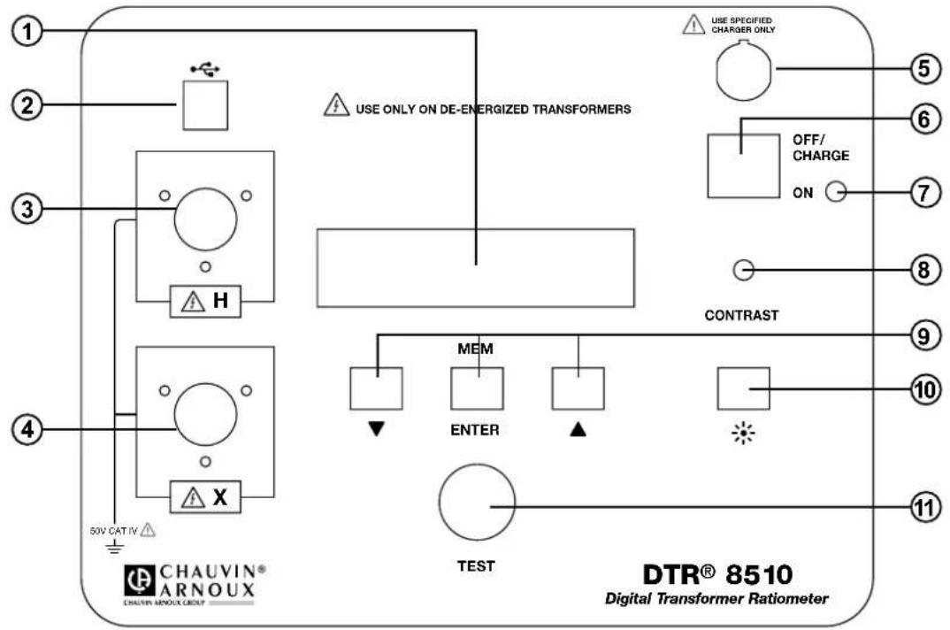
text_image
USE ONLY ON DE-ENERGIZED TRANSFORMERS USE SPECIFIED CHARGER ONLY OFF/CHARGE ON CONTRAST MEM ENTER TEST DTR® 8510 Digital Transformer Ratiometer- Display: Displays data, status and control features of the instrument.
- USB Connector: Allows connection to a computer for instrument configuration set-up and status check, downloading of the stored data using the DataView® software and running a test.
- High-side "H" Cable Connector (primary): Connection for the primary side of the transformer.
- Low-side "x" Cable Connector (secondary): Connection for the secondary side of the transformer.
- Battery Charge Input Connector: Allows the smart charger to charge the batteries.
- Power Switch: Turns the instrument ON or OFF (if the charger is not connected). If the charger is connected, the batteries charge in OFF/CHARGE position.
- Operation and Battery Low Indicator: Green LED indicates that the instrument is on and blinks when the batteries are getting low (<12 V). The instrument will completely shut down when the batteries are below 8.7 V.
- Display Contrast Adjustment: Allows adjustment of the display contrast.
- Function Keys: Allows navigation of the menu and functions of the instrument.
- Backlight (*) Control Button: Turns the display backlight ON or OFF.
- Test Button: Runs the selected test when pressed and released.
2.3. CABLE IDENTIFICATION
Primary (H) Cable:
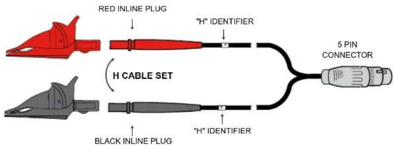
text_image
RED INLINE PLUG "H" IDENTIFIER H CABLE SET BLACK INLINE PLUG "H" IDENTIFIER 5 PIN CONNECTORSecondary (X) Cable:
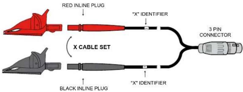
text_image
RED INLINE PLUG "X" IDENTIFIER X CABLE SET BLACK INLINE PLUG "X" IDENTIFIER 3 PIN CONNECTOREach cable is clearly marked. The Primary (H) cable has a 5-pin connector and the Secondary (X) cable has a 3-pin connector. They cannot inadvertently be connected incorrectly.
3. SPECIFICATIONS
Reference Conditions: 23^ ± 5^ (30 to 50% RH) range. Add 25 ppm/ ^ from -10 to 18°C and 28 to 50°C to all accuracy specifications. No external electrical or magnetic fields. Output current ≤ 150 mA for VT/PT and ≤ 50 mA for CT. Calibration cycle is 1 year.
3.1. DTR® 8510 SPECIFICATIONS
| ELECTRICAL | ||
| Ratio Range (VT/PT) | Autoranging: 0.8000 to 8000:1 | |
| Accuracy (VT/PT) | Ratio Range Accuracy (% of Reading) | |
| 0.8000 to 9.9999 ± 0.2% | ||
| 10.000 to 999.99 ± 0.1% | ||
| 1000.0 to 4999.9 ± 0.2% | ||
| 5000.0 to 8000.0 ± 0.25% | ||
| Ratio Range (CT) | Autoranging: 0.8000 to 1000.0 | |
| Accuracy (CT) | Ratio Range Accuracy (% of Reading) | |
| 0.8000 to 1000.0 ± 0.5% | ||
| Excitation Signal | VT/PT Mode: 32 Vrms maxCT Mode: Auto Level 0 to 1 A, 0.1 to 4.5 Vrms | |
| Excitation Current Display | Range: 0 to 1000 mAAccuracy: ± (2% of Reading + 2 mA) | |
| Excitation Frequency | 70 Hz | |
| Display | Dual line alpha-numeric LCD, 16x2 characters with contrast adjustment and backlight control. Day/night visible. | |
| Measurement Method | In accordance with IEEE Std C57.12.90TM | |
| Power Source | Two 12V, 5x2, 1650 mAH NiMH rechargeable battery packs | |
| Battery Life | Up to 10 hrs of continuous operation. Low battery indication. | |
| Battery Charger | Universal input (90 to 264 Vrms input) smart recharger | |
| Charging Time | < 4 hrs | |
| Data Storage | 99 objects with 99 tests each | |
| Date/ Time | Battery-backed, Real-time clock | |
| Communication | USB. 2.0 compliant, optically isolated, 115.2 kB | |
| Software | DataView® analysis software included | |
| MECHANICAL | ||
| Dimensions | 272 x 248 x 130 mm (10.70 x 9.76 x 5.12") | |
| Weight | 3.7kg (8.1 lbs) | |
| Connection | XLR connectors | |
| Leads | 4.6 m (15 ft+) H & X shielded with large color-coded industrial alligator clips in carrying bag | |
| Enclosure | Heavy duty Polypropylene case, UL 94 V0 | |
| Vibration | IEC 68-2-6 (1.5 mm to 55 Hz) | |
| Shock | IEC 68-2-27 (30 G) | |
| Drop | IEC 68-2-32 (1 m) | |
| Index of Protection | IP 40 (Instrument lid open) per EN 60529IP 53 (Instrument lid closed) per EN 60529 | |
| ENVIRONMENTAL | |
| Operating Temperature | -10° to 50°C |
| Storage Temperature | -20° to 60°C |
| Relative Humidity | 10 to 85% RH @ 35°C |
| Altitude | Up to 2000 meters (6560 ft) |
| SAFETY | |
| Safety Rating | EN 61010-1; 50 V CAT IV; Pollution Degree 2 |
| Double Insulated | Yes |
| CE Marking | Pending |
Specifications are subject to change without notice.
3.2. BATTERY CHARGER SPECIFICATIONS
| ELECTRICAL | |
| No-load Voltage | 41 V ±2 V |
| Fast Charge Current | 0.9 A ± 70 mA |
| Top-off Charge | 130 mA ± 40 mA |
| Charge Termination Options | -dV, dT/dt |
| Input Rating | 90 to 264 Vac /47 to 63 Hz |
| Maximum Output Power | 35 W |
| Trickle Charge Current | 50 mA ± 25 mA |
| Leakage Current (from battery with mains off) | < 1 mA |
| MECHANICAL | |
| Dimensions | 107 x 67 x 36.5 mm (4.22" x 2.64" x 1.44") |
| Weight | 250 g (0.55 lbs) |
| Input Connection | 2-pin IEC 320-C7 |
| Output Connection | NiMH: 3 PIN DIN |
| ENVIRONMENTAL | |
| Operating Temperature | -20° to 40°C |
| SAFETY | |
| Insulation Class | II |
| Electrical Safety Approval | EN 60601-1, EN 60950, EN 60335-2-29 |
| EMC Standards | EN 61000-6-3 (Emission), EN 61000-6-1 (Immunity) |
Specifications are subject to change without notice.
4.1. PROGRAM FLOW
In order to use the instrument efficiently, it is important to understand the program flow.
- Pressing the ▼ and ▲ keys simultaneously allows going up one level (if there is a level) in the program flow. (Vertical navigation moving up a level).
■ Pressing the ▼ or ▲ key allows navigation within the level. (Horizontal navigation). - Pressing the ENTER key allows the selection and display of choices one level below (if there is a level) in the program flow. (Vertical navigation moving down a level).
4.2. TOP LEVEL MENU
The instrument has a top level control as shown in Fig. 4-1.
The user can navigate around the ring by pressing the ▼ or ▲ key.
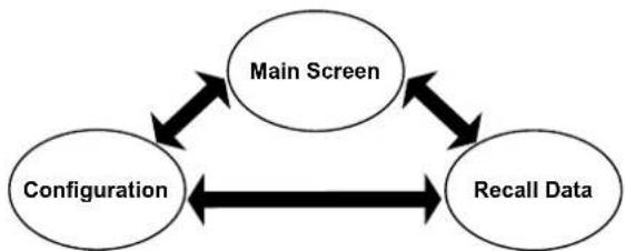
flowchart
graph TD
    A["Main Screen"] <--> B["Configuration"]
    B <--> C["Recall Data"]
    C <--> A
Figure 4-1
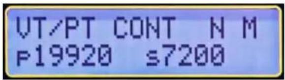
Once the instrument is turned on, it initializes and then displays the Main Screen:
text_image
VT/PT CONT N M F19920 ≤7200Figure 4-2
■ Main Screen: Displays the Test Type, Test Mode, Filter [Fast (F), Normal (N) or Slow (S)], Storage Mode [Auto (A) or Manual (M)] and the Present Nameplate values (if enabled).
■ Configure Instrument: Configures the instrument (see § 4.3).
■ Recall Data: Stored data can be selected and displayed (see § 4.4).

NOTE: The program flow is two or three levels deep at various points. The available choices for a level can be viewed by pressing the ▼ or ▲ keys.
The ENTER key is used to select the following functions:
■ Enter configuration menu.
■ Enter Recall Data menu.
■ Initiate storage of test results, accept location parameters and store the Measurement Record.
4.3. CONFIGURE INSTRUMENT
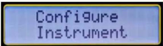
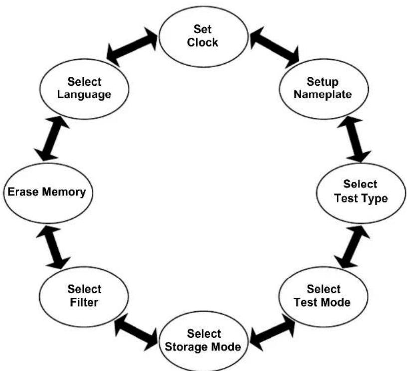
With the display showing Configure Instrument, press the ENTER key. The configuration ring (see Figure 4-4) can be navigated around using the ▼ or ▲ key.
text_image
Configure InstrumentFigure 4-3
■ Set Clock: Allows the setting of Time and Date.
■ Setup Nameplate: Allows selection and editing of Present Nameplate voltages or ratios. Predefined ratios can only be edited through DataView®.
■ Select Test Type: Allows the selection of Test Type (VT/PT or CT).
■ Select Test Mode: Allows selection of the Test Mode (Ratio or Continuity/ Ratio in VT/PT Mode).
■ Select Storage Mode: Allows the selection of data storage mode (Automatic or Manual).
■ Select Filter: Allows selection of filter (Fast, Normal, Slow). See § 4.3.6.
■ Erase Memory: Allows deletion of all the stored measurement records
■ Select Language: Allows selection of language on the display (English, French, German, Italian, Spanish, Portuguese)

NOTE: To move one level up and return to Configure Instrument, press the ▼ and ▲ keys simultaneously.
flowchart
graph TD
    A["Set Clock"] --> B["Setup Nameplate"]
    B --> C["Select Test Type"]
    C --> D["Select Test Mode"]
    D --> E["Select Storage Mode"]
    E --> F["Select Filter"]
    F --> G["Erase Memory"]
    G --> H["Select Language"]
    H --> A
Figure 4-4
4.3.1. SET CLOCK
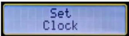
- Within the top level of Configure Instrument, press the ▼ or ▲ key until Set Clock appears on the display, then press ENTER.
text_image
Set ClockFigure 4-5
The Set Clock configuration allows you to format the following:
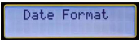
Date Format: Allows the formatting of the date. (MM/DD/YY, DD/MM/YY, YY/MM/DD).
text_image
Date Format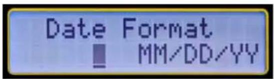
text_image
Date Format MM/DD/YYFigure 4-6
Time Format: Allows the formatting of the time (12 or 24 hours).
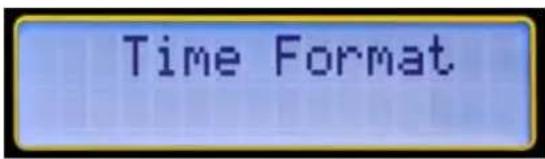
text_image
Time Format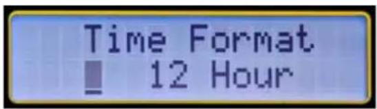
text_image
Time Format ■ 12 HourFigure 4-7
Set Date and Time: Allows the setting of the date and time in the selected format.
Note: Time must be set in the 24-hour format. It will be displayed with AM/PM if the 12-hour format is chosen.
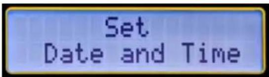
text_image
Set Date and Time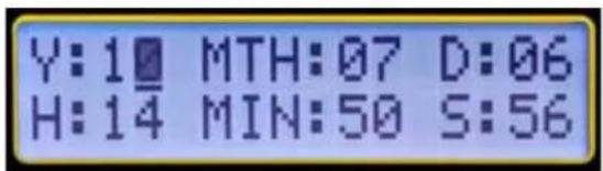
text_image
Y:10 MTH:07 D:06 H:14 MIN:50 S:56Figure 4-8
Example: To set the time to 2:50 PM, set the hour to 14 and the minutes to 50.
To maneuver between the Set Clock configuration settings, perform the following:
- Within the top level of Configure Instrument, press the ▼ or ▲ key until Set Clock appears on the display, then press ENTER to configure the date.
- Use the ▼ or ▲ keys to view the choices. Press ENTER to make a selection. Once the format is selected, the display returns to Date Format.
- Use the ▼ or ▲ keys to navigate to the other date and time options or press both ▼ and ▲ keys together to return to the top level.
4.3.2. SETUP NAMEPLATE
Nameplate values are primary and secondary voltages (or ratios) associated with a given transformer. This information is available on the Nameplate of the transformer. The measured results will be compared with selected (edited) Nameplate values and Deviation will be displayed and stored in % relative to these values.
The DTR ^® 8510 allows the storage of 10 Nameplate voltages or ratios which can be individually selected for a given test.
NOTE:
The Nameplate list of up to 10 transformers can be written to and saved only using DataView® software. The values in the list can be edited for use but cannot be saved from the front panel.
■ The keys on the front panel can select any one of the 10 transformer Nameplate values. Once the transformer values are selected, they can be edited to a new value using the ▼, ▲ and ENTER keys. When the new values are selected (even if they are not edited to new values), it becomes the Present Nameplate and will be used for all subsequent VT/PT and CT measurements. Deviation will be reported and stored using these values.
■ The Present Nameplate values will be retained in memory even if the instrument is turned OFF and turned ON. However, it will not be saved in the list from which it was originally selected.
The user can select another Nameplate from the list in the future and may or may not edit the values. As soon as the new Nameplate values are selected (and/or edited), it becomes the new Present Nameplate.
■ The Present Nameplate values are displayed in the Main Screen.
■ Each Measurement Record will record the Present Nameplate along with other associated parameters and will be available when the data is downloaded.
■ The Ratio of the nameplate values must be between 1 and 32767.
The Nameplate needs to be enabled. If the Nameplate is not enabled, the Deviation % will not be reported after the measurements. Subsequently, the stored values will not have Nameplate and Deviation % in the Measurement Record.

NOTE: The Main Screen will display the Present Nameplate only if it is Enabled. If it is not Enabled, it will display “---” for Primary and Secondary.
To configure the settings for the Nameplate, perform the following:
- Within the top level of Configure Instrument, press the ▼ or ▲ key until Setup Nameplate appears on the display, then press ENTER.
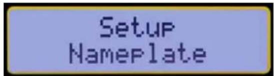
text_image
Setup NameplateFigure 4-9
- The display will show Enable with Yes and No choices. Press the ▼ key to select Yes (Enable Nameplate).

text_image
Enable YES NOFigure 4-10
- The display will now show the following screen:
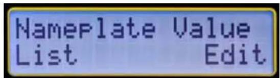
text_image
Nameplate Value List EditFigure 4-11
- Select List by pressing the ▼ key. The list can then be scrolled from 0 to 9 Nameplate values by using the ▼ or ▲ key. Select the desired Nameplate by pressing ENTER. The display will return to Setup Nameplate.
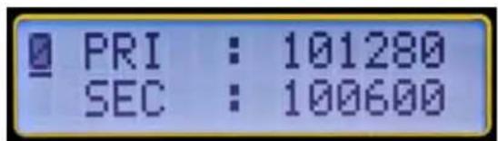
text_image
PRI : 101280 SEC : 100600Figure 4-12
- Press ENTER, then Yes (▼) on Enable.
- Select Edit by pressing the ▼ key. The values in the Present Nameplate can be edited digit by digit by selecting each digit with the ▼ or ▲ and then pressing the ENTER key. When the last digit on the Secondary is selected, the display returns to Setup Nameplate.
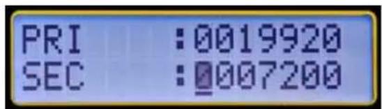
text_image
PRI :0019920 SEC :0007200Figure 4-13
NOTE:
■ Selecting one transformer from the list will replace the values in the Present Nameplate immediately. The values can then be changed in the Edit mode if needed.
■ Selecting Edit will allow the user to modify the values in the Present Nameplate.
■ The Edit process changes the values in the Present Nameplate only. The values previously stored would remain the same. The stored List values can only be changed in DataView®.
In order to write the Present Nameplate value, you must press ENTER until Setup Nameplate is displayed. Otherwise, the ratio will not be entered. If the up/down arrows are pressed after setting the ratio, then it performs a cancel operation and the changes will not be saved.

REMEMBER: In order to move one level up and return to Configure Instrument, press the ▼ and ▲ keys simultaneously. Text text text text.
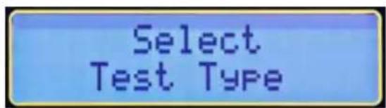
4.3.3. SELECT TEST TyPE
- From the top level of Configure Instrument, press the ▼ or ▲ key until Select Test Type appears on the display, then press ENTER.
text_image
Select Test TypeFigure 4-14
- Select VT/PT or CT using ▼ or ▲ and press ENTER. The display will return to Select Test Type.

NOTE: Once the Test Type is selected, it is retained until changed by the user. If the instrument is turned OFF and turned ON, the Test Type will be the same as last selected.
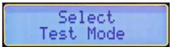
4.3.4. SELECT TEST MODE
- From the top level of Configure Instrument, press the ▼ or ▲ key until Select Test Mode appears on the display, then press ENTER.
text_image
Select Test ModeFigure 4-15
- Select Ratio or CONT/Ratio test using ▼ or ▲ and press ENTER. The display will return to Select Test Mode.
CONT/Ratio: Performs a Continuity test followed by Ratio test only in VT/PT. Continuity test is not available (N/A) in CT mode.
Ratio test: Performs only the Ratio test in the VT/PT or CT mode.

NOTE: Test Mode can also be selected from the Main Screen by pressing ENTER, which toggles the selection of CONT and Ratio.
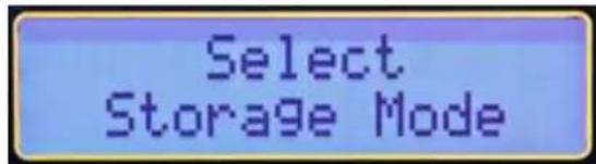
4.3.5. SELECT STORAGE MODE
- From the top level of Configure Instrument, press the ▼ or ▲ key until Select Storage Mode appears on the display, then press ENTER.
text_image
Select Storage ModeFigure 4-16
- Select Auto or Manual using ▼ or ▲ and press ENTER. The display will return to Configure Instrument > Select Storage Mode.
NOTE:
In Manual mode, the user has a choice at the end of a test whether to store the Measurement Record or not. The user also has a choice of where to store the Measurement Record. So it is possible for the user to store the Measurement Record at various locations leaving gaps in the storage memory map.
All Measurement Records will be downloaded no matter where they are stored in the memory.
In Auto mode, the instrument will store the Measurement Record at the end of a test starting with the first available location. All the subsequent Measurement Records will be stored sequentially.
If the previously stored Measurement Record is encountered, the Auto store mode will skip over and store the new Measurement Record in the next available location.

NOTE: If the DTR® 8510 is connected to a computer, Auto mode will be disabled. The Measurement Record will not be saved in the instrument but will be sent to the computer.
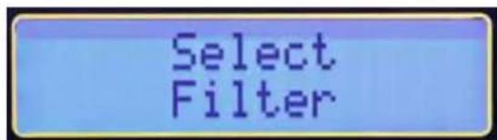
4.3.6. SELECT FILTER
- From the top level of Configure Instrument, press the ▼ or ▲ key until Select Filter appears on the display, then press ENTER.
text_image
Select FilterFigure 4-17
- Select Fast, Normal or Slow using ▼ or ▲ and press ENTER. The display will return to Configure Instrument > Select Filter.

NOTE: The DTR ^® 8510 offers the user a choice of three digital filters for measurement, depending upon the external electrical noise. These are sophisticated digital filters in the design which offer maximum noise rejection for repeatable measurements.
Digital Filters:
The digitalization of signal is done with Sigma-Delta ( - ) modulator. The output is a high frequency bit stream which is fed to a digital filter. The filtering of signal is performed with sophisticated sinc (Sinx/x) filter. The primary function of the filter is to remove the quantification noise introduced during the modulation process.
The filter limits the band of the allowed frequency to significantly lower than one-half of the frequency of the modulator itself. This reduces the 1-bit output of a comparator in a band-limited, very low noise output. The cut-off frequency and the decimated data rate are appropriately programmed in the internal registered and the output is arithmetically averaged to provide an accurate final answer.
High decimation results in lower noise but at a slower throughput rate. The calculation of arithmetic mean is a quick process at high clock speeds of the microprocessors.
The DTR ^® 8510 improves the quality of measurements in the following ways:
■ Low noise electronics
■ Shielded electronics and cables.
■ Differential measurements to reduce common-mode effects.
■ Ratiometric calculations to reduce dynamic errors.
VT/PT
| Fast Normal Slow | |||
| Approx Measurement Time | 6.5 S 9 S 19 S | ||
| Uses | Electrically Quiet Environment | In Most Applications | Electrically Very Noisy Environment |
CT
| Fast Normal Slow | |||
| Approx Measurement Time 14 S 16 S | 43 S | ||
| Uses Electrically Quiet | Environment | In Most Applications | Electrically Very Noisy Environment |
4.3.7. ERASE MEMORY
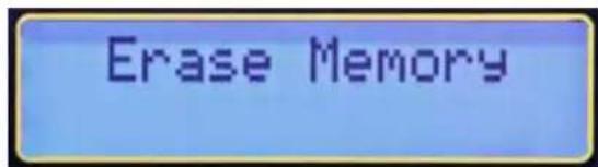
- Press the ▼ or ▲ key until Erase Memory appears on the display, then press ENTER.
text_image
Erase MemoryFigure 4-18
- Select Yes or No using ▼ or ▲ and press ENTER. The display will return to Erase Memory.

CAUTION: Once the memory is erased, the stored data cannot be recovered. Download the data, if desired, before the Erase Memory function is executed.
4.3.8. SELECT LANGUAGE
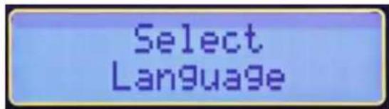
- Press the ▼ or ▲ key until Select Language appears on the display, then press ENTER.
text_image
Select LanguageFigure 4-19
- Select a language using ▼ or ▲ and press ENTER. The display will return to Select Language.
The following languages are available:
■ English
French
German
Italian
■ Spanish
Portuguese
Once the language is chosen, all the menu items, error messages etc. will be displayed in this language. The configuration retains the language if the instrument is turned OFF and then turned ON.

NOTE: The language can also be selected immediately at start up. Press and hold the TEST button while turning the unit ON. After initialization, the instrument will display the currently active language. Release the TEST button. The desired language can now be selected.
4.3.9. RESTORING FACTORY DEFAULTS
The factory default settings are shown in the following table:
| Parameter Default Value | |
| Test Mode Ratio | |
| Test Type VT/PT | |
| Filter Normal | |
| Storage Mode Manual | |
| Language English | |
| Nameplate Disable | |
| Nameplate Values | 19920:720019920:480019920:240019920:216019920:1207200:24007200:21607200:1202400:1202160:120 |
Table 4-1
To set the instrument back to the factory default configuration:
- Turn the DTR ^® 8510 OFF.
- Press and hold the ▲ button.
- Turn the DTR ^® 8510 ON.
- Release the ▲ button when the instrument beeps.

NOTE: The previously stored Measurement Records will remain in the memory and the language will remain the same as before the default configuration was loaded.
4.4. RECALL DATA
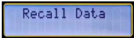
- From the Main Screen, press the ▼ or ▲ key until Recall Data appears on the display, then press ENTER.
text_image
Recall DataFigure 4-20
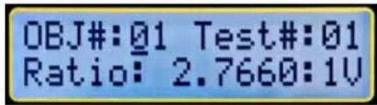
The Measurement Record in OBJECT #01 and TEST #01 will be displayed, as well as the Ratio.

NOTE: The V after the Ratio indicates the VT/PT test type. C would be displayed if the Ratio was from a CT test.
text_image
OBJ#:01 Test#:01 Ratio: 2.7660:1VFigure 4-21
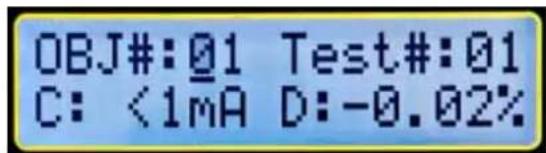
- Press the TEST button to move to second screen, which will display Current and Deviation %.
text_image
OBJ#:01 Test#:01 C: <1mA D:-0.02%Figure 4-22
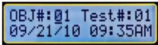
- Press the TEST button to move to the third screen to display the Date and Time.
text_image
OBJ#:01 Test#:01 09/21/10 09:35AMFigure 4-23
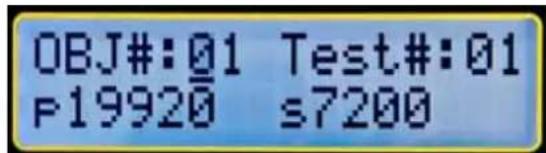
- Press the TEST button to move to the fourth screen to display the Primary and Secondary voltages of the Present Nameplate at the time the measurement was made.
text_image
OBJ#:01 Test#:01 P19920 s7200Figure 4-24
-
Press the TEST button again to return to the first screen.
-
Select any OBJECT and any TEST using the ▼ or ▲ key and the ENTER key to view the Measurement Record at any location.
NOTE:
■ The DTR510 can store 99 OBJECTs. Each OBJECT can store up to 99 TESTs.
In Manual mode, the user can select the location to store the Measurement Record. The Measurement Records do not have to necessarily be sequentially stored. So, during a Recall Data operation, it is important for the user to know where the data is

WARNING: The DTR® 8510 is designed for use on de-energized ("dead") transformers only. Make sure the test sample is completely disconnected from AC power and is fully discharged.
5.1. POWER UP
Turn the power switch to the ON position.
At power up, the instrument goes through an initialization process:
■ Beeps once
■ Displays "Initializing...Please Wait" for a short duration
■ Displays the Company Name and Firmware version number
■ Displays Date and Time for a short duration
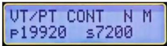
■ The instrument rests at the Main Screen which displays Test Type, Test Mode, Filter, Storage Mode and the present Nameplate values (Fig. 5-1)
■ The Green power LED on the front panel turns on solid
text_image
VT/PT CONT N M P19920 ≤7200Figure 5-1
NOTE:
If the batteries are insufficiently charged:
■ The Green LED will blink if there is some battery capacity left. The instrument will be operational under this condition.
The display will show Low Battery and the Green LED will blink if the battery packs have no capacity left. The instrument cannot be used for testing under these circumstances. The batteries must be recharged before use (see § 8.1).
5.2. RUNNING A TEST
5.2.1. VT/PT TEST
In this paragraph, an example of running a test using the following configuration (see § 4.3 for how to configure the instrument) is shown:
■ Set Date/Time: July 4, 2010. 6:00 PM
■ Set values in Nameplate:
Primary Voltage:19920; Secondary Voltage: 7200
■ Select Type: VT/PT
■ Select Test Mode: CONT/Ratio
■ Storage Mode: Manual
■ Set Filter: Normal
■ Set Language: English
- Typical Connection
RATIO 2.767 : 1
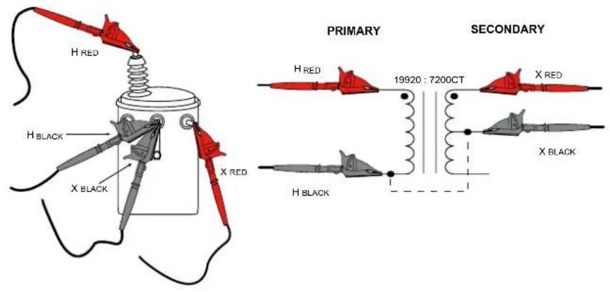
text_image
H RED H BLACK X BLACK X RED PRIMARY SECONDARY H RED 19920 : 7200CT X RED X BLACK H BLACK- Alternate Connection
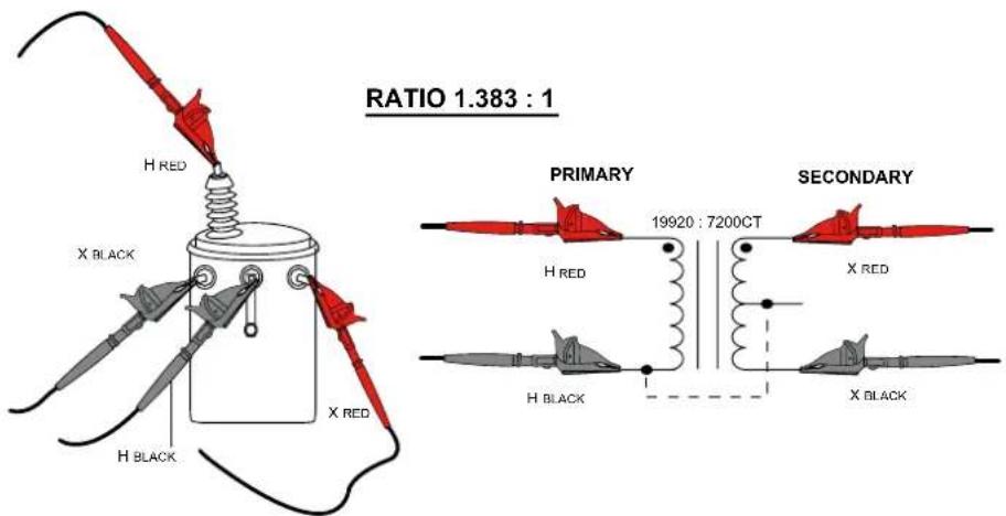
text_image
RATIO 1.383 : 1 H RED X BLACK H BLACK X RED PRIMARY 19920 : 7200CT H RED X RED H BLACK X BLACK SECONDARYFigure 5-2
- Connect the Primary (H) and Secondary (X) cables to the appropriate connectors on the DTR ^® 8510 and the transformer under test (see Fig. 5-2).
- Press TEST button. The test will run continuity first and then run the ratio test.
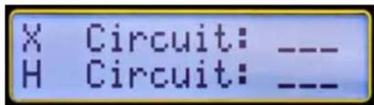
text_image
X Circuit: --- H Circuit:__Figure 5-3

WARNING: It is important to make sure the Primary (H) and the Secondary (X) cables are connected properly BEFORE running the test. This is especially true for the high turn-ratio transformers since dangerous high voltage may appear on the DTR® 8510 terminals.
NOTE:
■ Continuity checks for the integrity of the cable connections only. It does not check for H/X reverse polarity.
If the continuity for the Primary connections is within specified limits, the display shows ---- or equivalent to a Closed Switch. If the continuity for the Primary connections is outside the specified limits, the display shows --/-- or equivalent to an Open Switch.
■ During the Ratio test, the instrument will check for H/X reverse polarity, short (excessive current) etc. before conducting Ratio test.
In this example, the display will appear as shown below.
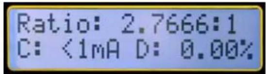
text_image
Ratio: 2.7666:1 C: <1mA D: 0.00%Figure 5-4
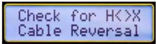
If the H/X were reversed, the instrument will display the following error message and terminate the test.
text_image
Check for H<>X Cable ReversalFigure 5-5
NOTE:
If there were a polarity reversal, the Ratio would be displayed negative and it would be blinking. This means either the connections are reversed on a given side or the transformer is wound backwards relative to the marking.
■ The test may be run as many times as needed by pressing the TEST button.
■ An active test can be cancelled at any time by pressing the TEST button.
■ Make sure that the HRED lead is always connected such that it does not short to the XRED or XBLACK lead directly or through earth ground. See § 6 for more connection details.
5.2.2. STORING THE MEASUREMENT RECORD (MANUAL AND AUTO MODE)
The storage mode you are in depends on what you selected when configuring the instrument (see § 4.3) before running a test.
5.2.2.1. Manual Mode
When Manual mode is selected, the Measurement Record storage is optional to the user.
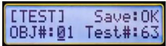
- To store the active measurement using Manual mode, press the MEM (ENTER) button. The display looks as shown below:
text_image
[TEST] Save:OK OBJ#:@1 Test#:63Figure 5-6
-
Select the OBJ and Test location using the ▼ or ▲ key and press ENTER.
-
Press ENTER or TEST to store the Measurement Record.
NOTE:
■ After the test is run, the new location is automatically increased sequentially from the last stored location.
If a given location is not available for storage, the Save field will display N/A.
In order to NOT STORE the Measurement Record, simply press the TEST button after the measurement is completed.
5.2.2.2. Auto Mode
When Auto mode is selected, the instrument requires no user input.
At the end of the test, the Measurement Record is stored in the location next to the first available location and then will store sequentially.

NOTE: If the previously stored Measurement Record is encountered, the Auto store mode will skip over and store the new Measurement Record in the next available location.
5.2.3. VT/PT ExCITATION CURRENT
Excitation current, displayed in milli-amperes (mA) is the RMS current in the Primary (H) winding due to test excitation. The loading on the Secondary (X) winding due to the DTR ^® 8510 is negligible.
■ The DTR8510 uses a maximum of 32 Vrms excitation voltage for testing. The displayed excitation current will almost always be a small fraction of transformer no-load excitation at full (rated) voltage. Most transformers will require less than 100 mA.
If you are presently using a ratiometer that employs secondary (X) side excitation (e.g. common hand-cranked instruments) in step-up mode, the current may be much higher than what the DTR® 8510 displays.
This is normal and results directly from the fact that in most step-down transformers, the Primary (H) side has a much higher impedance than its associated Secondary (X) winding.
5.2.4. VT/PT CONTINUITY TEST
The Continuity Test function of the DTR® 8510 serves as a useful means of identifying open primary and secondary windings, high resistance connections, open circuit breakers and blown fuses. When selected, the DTR® 8510 checks for continuity between its Secondary (X) and Primary (H) cables.
■ The DTR510 will indicate OPEN for circuits >4 kΩ and CONT for circuits <4 kΩ. Check these values. A small fraction of transformers (High inductance or high winding Ohmic DC resistance) may appear open.
The instrument checks for Secondary (X) connections first. Even if it is found open, it continues to check Primary (H) connections. Regardless of the outcome, the instrument proceeds to perform pre-test checks. Following the pre-test checks, if either X or H or both were found to be OPEN, the instrument will display the appropriate error message. Pressing the TEST button again will start a new Continuity test (assuming the user fixed the connection problem) again. If it passes the Continuity test, Ratio test will be executed.
■ Transformers with winding arrangement multiple, parallel paths (e.g., Delta type) may read CONT even if one or more windings may be OPEN.
5.2.5. CT TEST
In this paragraph, an example of running a test using the following configuration (see § 4.3 for how to configure the instrument) is shown:
■ Set Date/Time: July 4, 2010. 6:00 PM
■ Set values in Nameplate:
Primary Voltage:19920; Secondary Voltage: 7200
■ Select Type: VT/PT
■ Select Test Mode: CONT/Ratio
■ Storage Mode: Manual
■ Set Filter: Normal
■ Set Language: English
Note: CT test does not allow a CONT/Ratio option. It only runs a Ratio test.

WARNING: The DTR® 8510 is designed for use on de-energized ("dead") transformers only. Make sure the test sample is completely disconnected from AC power and is fully discharged.
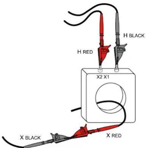
- Connect the Primary (H) cable to the appropriate connectors on the DTR ^® 8510 and the transformer under test. Connect the Secondary (X) cable as a loop through the current transformer hole as shown in the figure.
text_image
H RED H BLACK X2 X1 X BLACK X REDFigure 5-7
- Press the TEST button. During the Ratio test, the instrument will check for H/X reverse polarity, short (excessive current) etc. before conducting Ratio test.
NOTE:
■ If the H/X is reversed, the instrument will display the error message (see Fig. 5-5) as in VT/PT test and terminate the test.
If there were a polarity reversal, the Ratio would be blinking with a negative sign. This means either the connections are reversed on a given side or the transformer is wound backwards relative to the marking.
■ The test can be cancelled at any time by pressing the TEST button during the operation.
■ The CT test ramps up the voltage in steps. At the end of the test, it ramps down the voltage.
There are certain low mass, low ratio CT's for which the DTR8510 may not be able to provide correct ratio. The error message will be "High Excitation Current".
As in VT/PT, the CT test may be run as many times as needed by pressing the TEST button.
The measurement records can be saved in Manual or Auto mode as in VT/PT mode.
The CT remains active until the configuration is changed. Powering the instrument down and turning it back on will not change the Test Type.
5.3. TIPS FOR MAKING PRECISE RATIO MEASUREMENTS
The DTR® 8510 is designed for step-down transformers. It sources low voltage on the primary. It starts with a fraction of the final source voltage and checks the secondary voltage.
If it exceeds the primary by a pre-determined value, the safety feature stops the measurement. The recommended procedure is to reverse the leads in these circumstances so that the primary of the transformer is connected to the H cables and the secondary of the transformer is connected to the X cables.

CAUTION: It is important to check that the H cables are connected to the primary side and the X cables are connected to the secondary side of the transformer before the test begins.
■ Always verify the integrity of the cable connections and reposition the clips as necessary for robust and low-resistance connections. Inspect the transformer terminals for dielectric coatings, fungus, dirt or corrosion.
■ Running a continuity test before the ratio test will provide a useful way to check windings and connections.
■ When testing polyphase transformers, keep in mind that in some cases, the measured ratios must be multiplied or divided by 3 . Refer to § 6 for polyphase connection diagrams and associated ratio equations.
5.4. RATIO TEST - 1:1
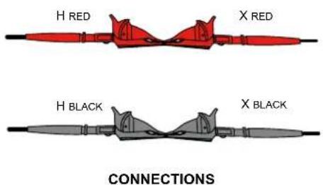
A simple test can be conducted to test functionality of the DTR® 8510.
-
Connect the H RED to XRED cable and separately connect the HBLACK to XBLACK. This connection simulates a 1:1 transformer.
-
Run VT/PT test.
In this connection mode, the test results should yield a ratio nearly equal to 1.0000. If it does not, the DTR ^® 8510 may require repair or re-calibration.
text_image
H RED X RED H BLACK X BLACK CONNECTIONS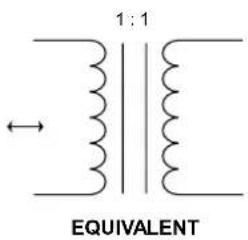
text_image
1:1 EQUIVALENTFigure 5-8
6. CONNECTIONS
6.1. CONNECTION DIAGRAMS
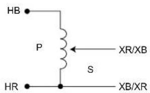
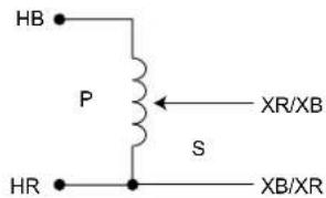
Make sure that the HRED lead is always connected such that it does not short to the XRED or XBLACK lead directly or through earth ground.
In the diagrams below, the top three are good connections but the bottom two should be avoided.
Measurements - OK
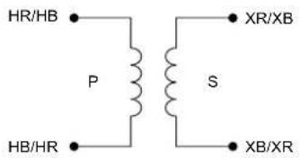
chemical
Electrical circuit diagram showing a transformer with primary and secondary windings labeled HR/HB, HB/HR, P, S, XR/XB, XB/XR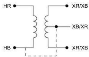
text_image
HR HB XR/XB XB/XR XR/XB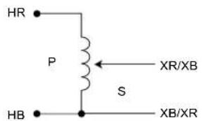
text_image
HR P S HB XR/XB XB/XRMeasurements - NOT OK
text_image
HB P XR/XB S HR XB/XR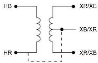
text_image
HB HR XR/XB XB/XR XR/XB6.2. POLyPHASE CONNECTIONS
| REF NO. | - TRANSFORMER - | XFMR TYPE | PHASE | HIGH VOLTAGE WINDING | LOW VOLTAGE WINDING | TURNS RATIO | |
| HIGH VOLTAGE WINDING | LOW VOLTAGE WINDING | ||||||
| 1 | 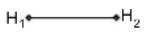 | 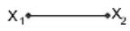 | 1 ∅ STD | 1 ∅ | H_1-H_2 | X_1-X_2 | _HV_X |
| 2 |  |  | Δ - Δ STD | A | H_1-H_3 (A) | X_1-X_3 (a) | _HV_X |
| B | H_2-H_1 (B) | X_2-X_1 (b) | |||||
| C | H_3-H_2 (C) | X_3-X_2 (c) | |||||
| 3 | 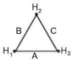 |  | Δ - Δ REV | A | H_1-H_3 (A) | X_1-X_3 (a) | _HV_X |
| B | H_2-H_1 (B) | X_2-X_1 (b) | |||||
| C | H_3-H_2 (C) | X_3-X_3 (c) | |||||
| 4 |  | 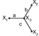 | Δ - Y STD | A | H_1-H_3 (A) | X_1-X_0 (a) | _H · [3]V_XV_X |
| B | H_2-H_1 (B) | X_2-X_0 (b) | |||||
| C | H_3-H_2 (C) | X_3-X_0 (c) | |||||
| 5 |  | 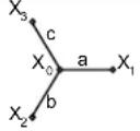 | Δ - Y REV | A | H_1-H_3 (A) | X_1-X_0 (a) | _H · [3]V_XV_X |
| B | H_2-H_1 (B) | X_2-X_0 (b) | |||||
| C | H_3-H_2 (C) | X_3-X_0 (c) | |||||
| 6 | 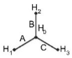 | 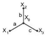 | Y - Y STD | A | H_1-H_0 (A) | X_1-X_0 (a) | _HV_X |
| B | H_2-H_0 (B) | X_2-X_0 (b) | |||||
| C | H_3-H_0 (C) | X_3-X_0 (c) | |||||
| 7 | 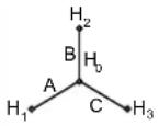 | 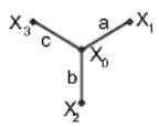 | Y - Y REV | A | H_1-H_0 (A) | X_1-X_0 (a) | _HV_X |
| B | H_2-H_0 (B) | X_2-X_0 (b) | |||||
| C | H_3-H_0 (C) | X_3-X_3 (c) | |||||
| 8 | 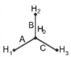 |  | Y - Δ STD | A | H_1-H_0 (A) | X_1-X_2 (a) | _HV_X · [3]3 |
| B | H_2-H_0 (B) | X_2-X_3 (b) | |||||
| C | H_3-H_0 (C) | X_3-X_1 (c) | |||||
| 9 | 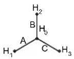 |  | Y - Δ REV | A | H_1-H_0 (A) | X_1-X_2 (a) | _HV_X · [3]3 |
| B | H_2-H_0 (B) | X_2-X_3 (b) | |||||
| C | H_3-H_0 (C | X_3-X_1 (c) | |||||
7.1. INSTALLING DATAVIEW®

DO NOT CONNECT THE INSTRUMENT TO THE PC BEFORE INSTALLING THE SOFTWARE AND DRIVERS.
Minimum Computer Requirements:
■ Windows XP / Windows Vista & Windows 7 (32/64 bit)
■ 256MB of RAM for Windows XP
1GB of RAM for Windows Vista & Windows 7 (32 bit)
2GB or RAM for Windows Vista & Windows 7 (64 bit)
■ 80MB of hard disk space (200MB recommended)
■ CD-ROMdrive
Windows is a registered trademark of Microsoft Corporation in the United States and other countries.
NOTE: When installing, the user must have Administrative access rights during the installation. The users access rights can be changed after the installation is complete.
DataView ^® must be reinstalled for each user in a multi-user system.
1. Insert the DataView ^® CD into your CD-ROM drive.
If auto-run is enabled, the Setup program will start automatically. If auto-run is not enabled, select Run from the Start menu and type in D:\SETUP (if your CD-ROM drive is drive D. If this is not the case, substitute the appropriate drive letter).

NOTE: If installing onto a Vista based computer the User Account Control dialog box will be displayed. Select the Allow option to proceed.
2. A Set-up window, similar to the one below, will appear.
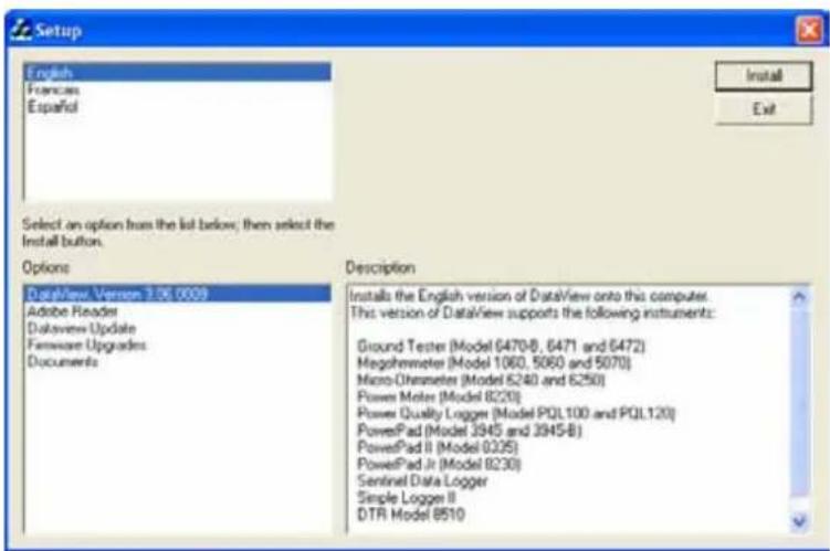
text_image
Setup English Francaes Español Install Exit Select an option from the list below, then select the Install button. Options DataView Version 3.06.0009 Adobe Reader DataView Update Firmware Upgrades Documents Description Installs the English version of DataView onto this computer. This version of DataView supports the following instruments: Ground Tester (Model 6470-B, 6471 and 6472) Megohemeter (Model 1060, 5060 and 5070) Micro-Character (Model 6240 and 6250) Power Meter (Model 8220) Power Quality Logger (Model PQL100 and PQL120) PowerPad (Model 3945 and 3945-B) PowerPad II (Model 8335) PowerPad Jr (Model 8230) Sentinel Data Logger Simple Logger II DTR Model 8510Figure 7-1
There are several different options to choose from. Some options ^(*) require an internet connection.
■ DataView, Version x.xx.xxxx - Installs DataView® onto the PC.
*Adobe Reader - Links to the Adobe® website to download the most recent version of Adobe® Reader to the computer. Adobe® Reader is required for viewing PDF documents supplied with DataView® that are accessible from the Help menu.
■ *DataView Updates - Links to the online AEMC® software updates to check for new software version releases.
■ *Firmware Upgrades - Links to the online AEMC® firmware updates to check for new firmware version releases.
- Documents - Shows a list of instrument related documents that you can view. Adobe® Reader is required for viewing PDF documents supplied with DataView®.
- DataView, Version x.xx.xxxx option should be selected by default. Select the desired language and then click on Install.
- The Installation Wizard window will appear. Click Next.
- To proceed, accept the terms of the license agreement and click Next.
- In the Customer Information window, enter a Name and Company, then click Next.
- In the Setup Type window that appears, select the Complete radio button option, then click Next.
- In the Select Features window that appears, deselect the instrument's control panel that you do not want to install, then click Next.

NOTE: The PDF-XChange option must be selected to be able to generate PDF reports from within DataView®.
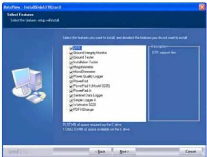
text_image
DataView - InstallShield Wizard Select Features Select the features setup will install. Select the features you want to install, and deselect the features you do not want to install QTR Ground Integrity Monika Ground Tester Installation Tester Megohorometers MicroOrimeter Power Quality Logger PowerPad PowerPad II (Model 0335) PowerPad Jr Sentinel Data Logger Simple Logger II Watermeter 8200 PDF-VIChange 31.52 MB of space required on the C drive 172882.03 MB of space available on the C drive Description: QTR support file Install / No < Back Next > CancelFigure 7-2
-
In the Ready to Install the Program window, click on Install.
-
If the instrument selected for installation requires the use of a USB port, a warning box will appear, similar to Figure 7-3. Click OK.

text_image
DataView - InstallShield Wizard Do not connect the AEMC USB Instrument (or cable) until after the installation of the drivers and the DataView software has finished. If the AEMC USB Instrument (or cable) is connected to the computer now then disconnect it from the computer before proceeding. OKFigure 7-3

NOTE: The installation of the drivers may take a few moments. Windows may even indicate that it is not responding, however it is running. Please wait for it to finish.
- When the drivers are finished installing, the Installation Successful dialog box will appear. Click on OK.
- Next, the Installation Wizard Complete window will appear. Click on Finish.
- A Question dialog box appears next. Click Yes to read the procedure for connecting the instrument to the USB port on the computer.

NOTE: The Set-up window remains open. You may now select another option to download (e.g. Adobe® Reader), or close the window.
- Restart your computer, then connect the instrument to the computer.
- Once connected, the Found New Hardware dialog box will appear. Windows will complete the driver installation process automatically.
Shortcuts for DataView ^® and each instrument control panel selected during the installation process have been added to your desktop.

NOTE: If you connected your instrument to the computer before installing the software and drivers, you may need to use the Add/Remove Hardware utility to remove the instrument driver before repeating the process.
7.2. OPENING THE CONTROL PANEL
The Control Panel can be opened from the DTR icon or from DataView ^® .
To open the Control Panel using the desktop icon:
■ Double-click the DTR Icon that was created during installation, located on the desktop.
■ The Connection window will appear. Click OK.
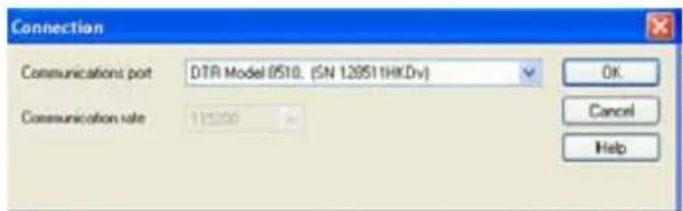
text_image
Connection Communications port DTR Model 0510. (SN 129511HKDv) Communication rate 115200 OK Cancel HelpFigure 7-4
To open the Control Panel from DataView®:
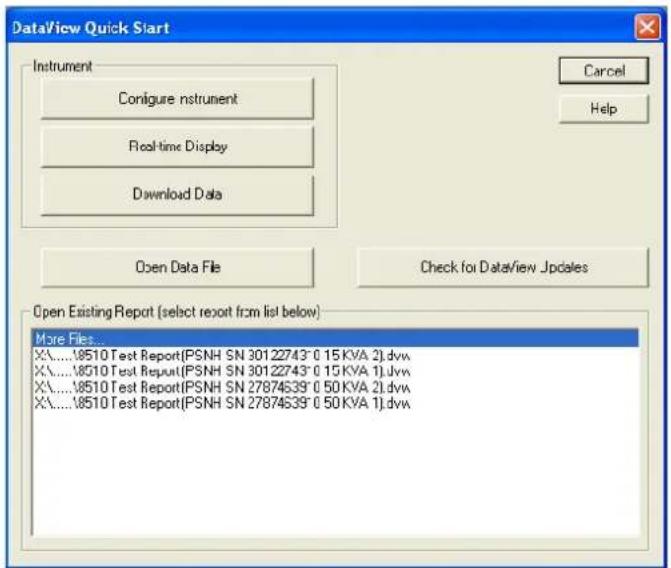
Double-click on the DataView icon on your desktop. The DataView ^® splash screen with a logo and relevant information will be displayed for a few seconds and then the Quick Start dialog box will appear (see Fig. 7-5).
text_image
DataView Quick Start Instrument Configure instrument Real-time Display Download Data Open Data File Check for DataView Updates Open Existing Report (select report from list below) More Files X:\...\18510 Test Report\PSNH SN 30122743° 0.15KVA 2].dvy X:\...\18510 Test Report\PSNH SN 30122743° 0.15KVA 1].dvy X:\...\18510 Test Report\PSNH SN 27874539° 0.50KVA 2].dvy X:\...\18510 Test Report\PSNH SN 27874539° 0.50KVA 1].dvyFigure 7-5
Select Configure Instrument. The Select Instrument dialog box will appear.
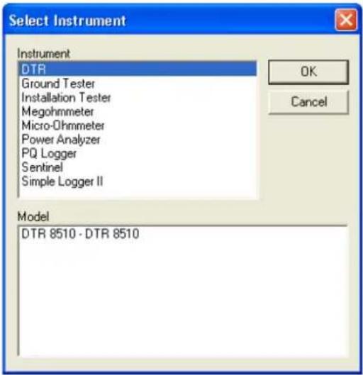
text_image
Select Instrument Instrument DTR Ground Tester Installation Tester Megohmmeter Micro-Ohmmeter Power Analyzer PQ Logger Sentinel Simple Logger II Model DTR 8510 - DTR 8510 OK CancelFigure 7-6
Select DTR and press OK. The Connection dialog box will appear (see Fig. 7-4).
The Connection window specifies the connected instrument in the communications drop-down list.
If multiple units are attached, select the desired unit with its associated serial number from the drop-down list. Once the desired instrument has been selected, click OK and the DTR® 8510 Control Panel and Configuration window will open (see Fig. 7-8).
7.3. USING THE CONTROL PANEL
The Control Panel is used for instrument operation and configuration.
To open the Control Panel refer to § 7.2.
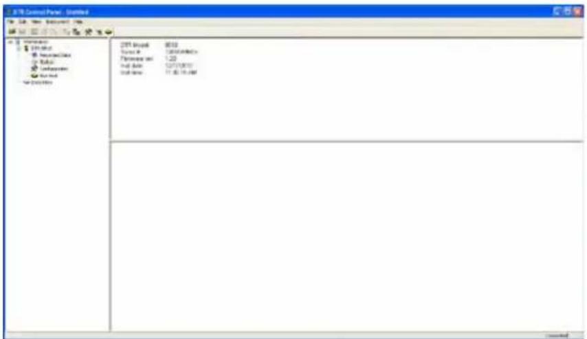
text_image
FTP Control Panel - Untitled FTP Control Panel: Untitled FTP Control Panel: Untitled FTP Control Panel: Untitled FTP Control Panel: Untitled FTP Control Panel: Untitled FTP Control Panel: Untitled FTP Control Panel: Untitled FTP Control Panel: Untitled FTP Control Panel: Untitled FTP Control Panel: Untitled FTP Control Panel: Untitled FTP Control Panel: Untitled FTP Control Panel: Untitled FTP Control Panel: Untitled FTP Control Panel: Unt titled FTP Control Panel: Untitled FTP Control Panel: Untitled FTP Control Panel: Untitled FTP Control Panel: Untitled FTP Control Panel: Untitled FTP Control Panel: Untitled FTP Control Panel: Untitled FTP Control Panel: Untitled FTP Control Panel: Untitled FTP Control Panel: Untitled FTP Control Panel: Untitled FTP Control Panel: Untitled FTP Control Panel: Untitled FTP Control Panel: Untitled ftp10000000000000000000000000000000000000000000000000000000000000000000000000000000000000000000000000000 FTP Control Panel: Untitled FTP Control Panel: Untitled FTP Control Panel: Untitled FTP Control Panel: Untitled FTP Control Panel: Untitled FTP Control Panel: Untitled FTP Control Panel: Untitled FTP Control Panel: Untitled FTP Control Panel: Untitled FTP Control Panel: Untitled FTP Control Panel: Untitled FTP Control Panel: Untitled FTP Control Panel: Untitled FTP Control Panel: Untitled FP1234678888888888888888888888888888888888888888888888888888888888888888888888888888888888888888888888888888Figure 7-7
The main menu at the top of the screen lists the following commands:
File
Open - Opens a DTR *.icp file
Save - Saves the report file in the appropriate folder
Save as - Permits the user to save the report at the location of his choice
Create DataView Report - Generates report for the open test results
Print Test - Prints the result of the test
Print Preview - Provides a preview of the selected test to be printed
Print All Tests - Prints all the tests in the selected Object
Print - Prints the selected real-time window
Print Preview All Tests - Provides a preview of all tests to be printed
Print Setup - Displays a Print Setup window allowing you to select a destination printer and change various printing options
Exit - Closes the control panel
Edit
Edit - Edits the session information for the selected test in the opened *.icp file
Delete - Deletes the current test from the *.icp file
View
Toolbar - Allows selection to view the toolbar
Status bar - Allows selection to view the status bar
Split - Allows splitting the screen to view the information
Instrument
Connect - Establishes a connection with the instrument
Disconnect - Closes the connection with the instrument
Configure - Displays the instrument configuration window
Download - Downloads recorded data stored in the DTR® 8510
Run Test - Allows running a test from the computer
Help
Help Topics - Displays the Control Panel help topic
About DTR - Displays a dialog box providing the current version number of the DTR® 8510 and DataView® software
7.4. CONFIGURING THE DTR® 8510
To Configure the DTR® 8510, perform the following steps:
- Open the Control Panel and connect to the instrument. To open the Control Panel refer to § 7.2
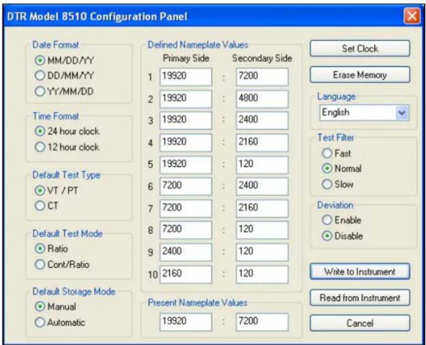
- Next, select Configure from the Instrument menu or click on the Configure icon ✗. The Configure Instrument dialog box will be displayed.
text_image
DTR Model 8510 Configuration Panel Date Format MM/DD/YY DD/MM/YY YY/MM/DD Time Format 24 hour clock 12 hour clock Default Test Type VT / PT CT Default Test Mode Ratio Cont/Ratio Default Storage Mode Manual Automatic Defined Nameplate Values Primary Side Secondary Side 1 19920 : 7200 2 19920 : 4800 3 19920 : 2400 4 19920 : 2160 5 19920 : 120 6 7200 : 2400 7 7200 : 2160 8 7200 : 120 9 2400 : 120 10 2160 : 120 Present Nameplate Values 19920 : 7200 Set Clock Erase Memory Language English Test Filter Fast Normal Slow Deviation Enable Disable Write to Instrument Read from Instrument CancelFigure 7-8
Date Format: Allows selection of the Date Format as MM/DD/YY or DD/MM/YY or YY/MM/DD.
Time format: Allows selection of Time format as 24-hour or 12-hour format.
Default Test Type: Allows selection of VT/PT or CT test.
Default Test Mode: Allows selection of test for Ratio only or Cont/Ratio (Continuity and Ratio) mode.
Default Storage Mode: Allows selection of storage of each Measurement Record in Manual or Automatic mode.
Default Nameplate Values: Allows the user to store the most frequently used nameplate values (or ratio values).
Present Nameplate Values: Allows the selection of the present nameplate values. The Deviation (%) will be calculated based on the Present Nameplate values for each measurement.
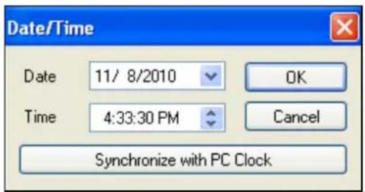
Set Clock: Allows setting the clock on the instrument manually or synchronized with the clock in the computer.
text_image
Date/Time Date 11/ 8/2010 OK Time 4:33:30 PM Cancel Synchronize with PC ClockFigure 7-9
Erase Memory: Allows the memory to be completely erased.
Language: Allows the selection of English, French, German, Italian or Portuguese.
Write To Instrument: Allows the present configuration values to be written in the instrument.

NOTE: None of the changes made on the configuration screen take effect until Write to Instrument command is executed.
Read from Instrument: Allows the present configuration to be read.
Cancel: Cancels the process to modify the configuration and closes the dialog box.

NOTE: Parameters changed after Write to Instrument was executed will be lost.
7.5. RUNNING A TEST
- Open the Control Panel and connect to the instrument.
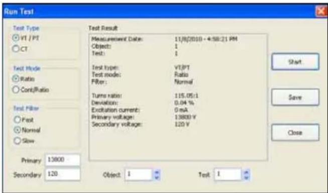
- Next, select Run Test from the Instrument menu or click on the Run Test icon 🙏 on the side or top menu.
text_image
Run Test Test Type VT / PT CT Test Mode Ratio Cont/Ratio Test Filter Post Normal Slow Primary 13000 Secondary 120 Test Result Measurement Date: 11/8/2010 - 4:58:21 PM Object: 1 Test: 1 Test type: VT/PT Test mode: Ratio Filter: Normal Turn ratio: 115.05:1 Deviation: 0.04 % Excitation current: 0 mA Primary voltage: 13800 V Secondary voltage: 120 V Object: 1 Test 1 Start Save CloseFigure 7-10
The user can select Test Type, Test Mode, Test Filter, Present Nameplate values and where the Measurement Record would be stored.
- Press Start to run the test. The result (Measurement Record) of the Test will be displayed in the center.
NOTE:
If the DTR8510 is in Autosave mode, the connection to the computer will disable the automatic saving of the Measurement Record.
■ If the Test needs to be cancelled while testing is in progress, press the TEST button on the instrument or CANCEL button on the screen.
■ If new Test Type, Test Mode, test Filter and/or Present Nameplate values are selected, the Configuration will be changed to reflect them in this and the following tests.
- Press Save to save the Measurement Record in the selected Object and Test locations, then press Close to close the dialog box.

NOTE: Pressing Save in the dialog box only saves the test to the instrument, NOT the computer. To save the test on the computer, select Save from the File menu.
7.6. DOWNLOADING A TEST
This selection permits downloading of the stored Measurement Records from the instrument.
To download a test:
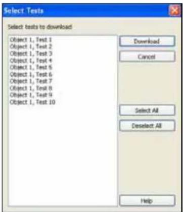
- Click on the Download icon 📄 in the toolbar, or click on Recorded Data on the side menu. The Select Tests dialog box will appear:
text_image
Select Tests Select tests to download Object 1, Test 1 Object 1, Test 2 Object 1, Test 3 Object 1, Test 4 Object 1, Test 5 Object 1, Test 6 Object 1, Test 7 Object 1, Test 8 Object 1, Test 9 Object 1, Test 10 Download Cancel Select All Deselect All HelpFigure 7-11
This dialog box displays the content of the memory. No Measurement Records are downloaded as yet.
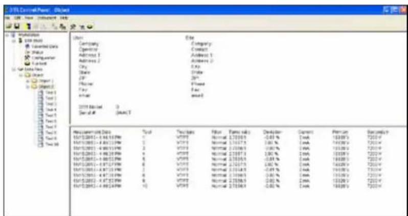
- Select the Measurement Records individually or press Select All. Press Download to get the data to the computer.
text_image
3P Control Power: Global File Edit View Help Name Company Company Operator Contact Address 1 Address 2 Address 2 Address 3 City Ex State Drive SP 20" Phone Fixed Fax Email 3P Control 0 Serial # (SAACT) Reconciliation Data Tool Truckbox Filter Type risks Developer Current Version Selection UST/08/2015-4.96117PM 1 VTPF Normal 275653 -0.01% CMA 18300V 7200V UST/08/2015-4.96117PM 2 VTPF Normal 275653 -0.01% CMA 18300V 7200V UST/08/2015-4.96117PM 3 VTPF Normal 275653 -0.01% CMA 18300V 7200V UST/08/2015-4.96117PM 4 VTPF Normal 275653 -0.01% CMA 18300V 7200V UST/08/2015-4.96117PM 5 VTPF Normal 275653 -0.01% CMA 18300V 7200V UST/08/2015-4.96117PM 6 VTPF Normal 275653 -0.01% CMA 18300V 7200V UST/08/2015-4.96117PM 7 VTPF Normal 275653 -0.01% CMA 18300V 7200V UST/08/2015-4.96117PM 8 VTPF Normal 275653 -0.01% CMA 18300V 7200V UST/08/2015-4.96117PM 9 VTPF Normal 275653 -0.01% CMA 18300V 7200VFigure 7-12
7.7. SAVING THE MEASUREMENT RECORDS
- Select Save or Save As from the File menu. The Save As dialog box will appear:
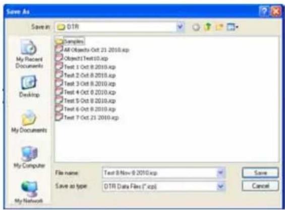
text_image
Save As Save in: OTR Samples All Objects - Oct 21 2010 (.cp) Object1 Text10 (.cp) Test 1 Oct 8 2010 (.cp) Test 2 Oct 8 2010 (.cp) Test 3 Oct 8 2010 (.cp) Test 4 Oct 8 2010 (.cp) Test 5 Oct 8 2010 (.cp) Test 6 Oct 8 2010 (.cp) Test 7 Oct 21 2010 (.cp) File name: Text 8-Nov-8 2010 (.cp) Save as type: OTR Data Files (*.cpx) Save CancelFigure 7-13
- Save the file in the default location of "My Documents\DataView\DataFiles\DTR" or select a different folder to save to.
To generate a report, a file needs to be open.
- Select Open from the File menu. If necessary, navigate to the appropriate folder where the .icp file is located, select it and press Open.
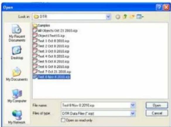
text_image
Open Look in: DTR Samples All Objects Oct 21 2010.kp Object 1 Text 10.kp Text 1 Oct 8 2010.kp Text 2 Oct 8 2010.kp Text 3 Oct 9 2010.kp Text 4 Oct 8 2010.kp Text 5 Oct 8 2010.kp Text 6 Oct 8 2010.kp Text 7 Oct 21 2010.kp Text 8 Nov 8 2010.kp File name: Text 8 Nov 9 2010.kp Files of type: DTR Data Files (*.kpc) Open as read-only My Recent Documents Desktop My Documents My Computer My NetworkFigure 7-14
Once the file is open, select Create DataView Report from the File menu or click on the Create DataView Report icon. A report will appear on the screen.
| Index | Date | Time | Object Name | Name | Turns Ratio Deviation | Current | Primary | Secondary | |
| 1 | 11/15/2010 | 4:44:18.000 PM | Object | Test 1 | 2.7665:1 | -0.01 % | 0 mA | 19920 V | 7230 V |
| 2 | 11/15/2010 | 4:45:32.000 PM | Object | Test 2 | 2.7667:1 | 0.00 % | 0 mA | 19920 V | 7230 V |
| 3 | 11/15/2010 | 4:46:19.000 PM | Object | Test 3 | 2.7666:1 | -0.00 % | 0 mA | 19920 V | 7230 V |
| 4 | 11/15/2010 | 4:46:36.000 PM | Object | Test 4 | 2.7667:1 | 0.00 % | 0 mA | 19920 V | 7230 V |
| 5 | 11/15/2010 | 4:46:50.000 PM | Object | Test 5 | 2.7665:1 | -0.01 % | 0 mA | 19920 V | 7230 V |
| 6 | 11/15/2010 | 4:47:07.000 PM | Object | Test 6 | 2.7667:1 | 0.00 % | 0 mA | 19920 V | 7230 V |
| 7 | 11/15/2010 | 4:47:21.000 PM | Object | Test 7 | 2.7664:1 | -0.01 % | 0 mA | 19920 V | 7230 V |
| 8 | 11/15/2010 | 4:47:36.000 PM | Object | Test 8 | 2.7666:1 | -0.00 % | 0 mA | 19920 V | 7230 V |
| 9 | 11/15/2010 | 4:47:50.000 PM | Object | Test 9 | 2.7666:1 | -0.00 % | 0 mA | 19920 V | 7230 V |
| 10 | 11/15/2010 | 4:48:04.000 PM | Object | Test 10 | 2.7666:1 | -0.00 % | 0 mA | 19920 V | 7230 V |
Figure 7-15
NOTE:
All downloaded files and reports are saved in the default location of "My Documents" or "Documents" for each user.
■ DataView and Control Panel (CP) are fully integrated programs for instrument control and data analysis/report generation. CP can download the Measurement Records previously stored in the DTR® 8510 memory. These Measurement Records can be stored in the *.icp format. Reports can be generated by a single click on the "icon" or create DataView Report from the File menu. When a report is created, a database file *.dvb is automatically created.
■ DataViewcan also call the CP or the CP of other instruments.
■ DataView cannot open *.icp files.
■ When a report is created from the CP, a report can be stored. In the process a *.dvw file is generated.
■ DataView can also create a report from the available database files. A *.dvb file is automatically created when the CP creates a report from *.icp file.
■ When a report is created, a *.dvw file is created. This report can be directly opened from DataView®.

NOTE: For more information about using DataView ^® , refer to the DataView ^® manual that is included on the installation CD. This manual can also be found online at www.aemc.com on our software download page for DataView ^® .
8. MAINTENANCE

The manufacturer cannot be held liable for any accident that occurs following a repair not performed by its customer service department or by an approved repairer.
8.1. CHARGING THE BATTERIES
The DTR® 8510 is supplied with an external smart charging unit. In order to charge the NiMH battery packs, the instrument switch must be in the OFF/CHARGE position.
Connect the charger unit output cable to the 3-pin DIN connector on the front panel of the instrument and connect the AC power cord to the AC receptacle.
The charging starts as soon as the power is applied, the process is automatic and will terminate on its own upon completion.

CAUTION:
■ Do not use any other charger.
■ Do not connect DC power supply. Damage will occur to the instrument.
■ The DTR510 must be charged indoors.
■ Disconnect the charger upon completion of the charging process. NiMH battery manufacturers do not allow trickle charge for a long time on a recurring basis.
Note:
■ The DTR8510 Power Switch must be in the OFF/CHARGE position in order for the unit to charge.
■ The DTR8510 cannot be used to test while it is charging.
There is no indication on the front panel about the status of charging or its completion. The Status LED is on the charger unit itself (see Figure 8-1).
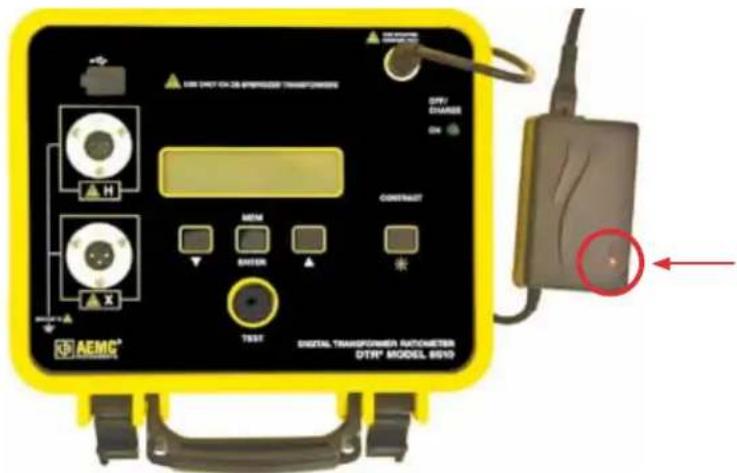
text_image
AEMC® H X TEST DIGITAL TRANSPORTER AUTOMETER DTR® MODEL 8610 CONTRAIT METH CENTER * NETT ON ON ON ON ON ON ON ON ON ON ON ON ON ON ON ON ON ON ON ON ON ON ON ON ON ON ON ON ON ON ON ON ON ON ON ON ON ON ON ON ON ON ON ON ON ON ON ON ON ON OnFigure 8-1
| Charge Cycle and Status LED Indication on the Charger | |
| LED MODE | |
| Orange Battery not connected | |
| Orange Battery initialization & analysis | |
| Red Fast Charge | |
| Green with Intermittent Orange Flash Top-off charge | |
| Green Trickle charge | |
| Alternating Red-Green Error | |
Table 8-1
The smart charger has the following features:
■ Multiple charge detection methods -dV (typical) and dT/dt.
Typically, the indication that the battery is fully charged is detected by a slight drop in its voltage (-dV). However, if the batteries are unused for a long time, they may display the same drop in voltage in the early part of the charge cycle even if they are not fully charged. This is a false indication. In order to prevent the termination of charge cycle due to this false indication, there is an integral timer built in the charger which will disregard the -dV for the first minutes of the charge cycle.
The battery packs are built with a thermistor. The smart charger constantly monitors the battery pack temperature. A built-in temperature charge control (+dT/dt) secures optimal charge.
■ Safety timer termination.
In case the batteries do not exhibit sufficient -dV/dt for the charger to detect, there is an internal safety timer which is custom-programmed for the battery packs used in the DTR® 8510.
■ Fast charging cycle.
This charge cycle supplies a maximum 900mA charge until -dV is detected.
■ Integral start timer to prevent initial, false -dV detection.
A few battery cells may have a voltage drop (-dV) in the first part of the charge cycle. This is especially true for battery cells which have been idle for a long period of time. Because of this, a start-timer built into the charger prevents -dV detection in the first minutes of the charger cycle.
■ Reverse polarity/short circuit protection.
The charger is protected against reverse polarity by an automatically resettable polyswitch fuse on the output.
■ LED status indicator (see Table 8-1).
■ Universal input voltage.
With the use of a proper power cord, the charger can be connected to standard AC receptacle anywhere in the world without the need for an external transformer.
Functionality:
Charging begins when the charger is connected to the DTR ^® 8510 and the power switch is in the OFF position. The LED will be orange before the fast charge starts. The LED will change to red when the fast charge cycle begins. When the cells are fully charged and the voltage drops (because of the -dV signal from the cells), the charger will go into a top-off charge mode before switching to trickle charge mode.
During the top-off charge session, the LED will be green with short, intermittent orange flashes. When the top-off charge is complete, the charger will go into trickle charge mode, changing the LED color to green. The charge current is now reduced to a safe level. However, trickle charging in excess of 12 hours on routine basis could be damaging for NiMH batteries.
If the safety timer disconnects before -dV, the top-off charge will not be engaged. The charger will then go directly to trickle charge mode and the LED will turn green. If the battery voltage is far below normal, the charger will stop the fast charge current and switch to trickle charge mode. The LED will then indicate an “error” by flickering green and red. The battery packs and/or the charger may need to be replaced.
If the line power is turned off, the charger will reset and start a new charge cycle when it is turned on again.
8.2. CLEANING

Disconnect the instrument from any source of electricity.
Use a soft cloth, dampened with soapy water. Rinse with a damp cloth and dry rapidly with a dry cloth or forced air. Do not use alcohol, solvents, or hydrocarbons.
8.3. METROLOGICAL CHECK
Like all measuring or testing devices, the instrument must be checked regularly.
This instrument should be checked at least once a year. For checking and calibration, contact one of our accredited metrology laboratories (information and contact details available on request), at our Chauvin Arnoux subsidiary or the branch in your country.
8.4. REPAIR
For all repairs before or after expiry of warranty, please return the device to your distributor.
9. APPENDIX: DISPLAY MESSAGES
Check for H<>X Cable Reversal
The DTR ^® 8510 may have detected a potentially hazardous step-up condition while attempting to test the transformer as connected. Verify connections.
High Excitation Current
Check test cable connections for inadvertent short circuits. Check for shorted transformer windings.
Low Battery
As the batteries are drained during use, the green LED will begin to flash when the battery voltage reaches a pre-determined threshold. The tests can be run as usual during this time but the batteries will soon need to be charged.
As the batteries reach a predetermined threshold, LOW BATTERY indication will appear on the display. All the buttons will be non-operational now. The batteries must be recharged in order to continue testing.

NOTE: The DTR® 8510 charges in < 4 hours. The instrument can not be used to test when the batteries are charging.
X Circuit CONT or OPEN
The ---- indication is for CONT (Closed switch). It indicates a good connection.
The --/-- indication is for OPEN (Open switch). It indicates a poor or open connection.
The message "Check X Connection" will be displayed.
H Circuit CONT or OPEN
The ---- indication is for CONT (Closed switch).
The --/-- indication is for OPEN (Open switch)
The message "Check H Connection" will be displayed.
Note: If both H and X connections are open, "Check H X connection" will be displayed.
Low X Signal
Check Secondary (X) cables for inadvertent short.
Check to make sure the Secondary (X) cable is connected properly at the instrument panel.
Secondary (X) winding may be shorted or the transformer circuit breaker may be open or the ratio may be higher than the instrument can measure.
Low H Signal
Check Primary (H) cables for inadvertent short.
Check to make sure the Primary (H) cable is connected properly at the instrument panel.
Primary (H) winding may be shorted.
Memory is Full! Data NOT stored
The instrument memory is full and there is no more location left for additional storage.
Memory Error! Service Required
Measurement Records cannot be stored or recalled because the memory cannot be accessed. Factory service is needed. However, the DTR ^® 8510 can be used to make measurements in a normal manner.
10. WARRANTY
Except as otherwise stated, our warranty is valid for twelve months starting from the date on which the equipment was sold. Extract from our General Conditions of Sale provided on request.
The warranty does not apply in the following cases:
■ Inappropriate use of the equipment or use with incompatible equipment;
■ Modifications made to the equipment without the explicit permission of the manufacturer's technical staff;
■ Work done on the device by a person not approved by the manufacturer;
■ Adaptation to a particular application not anticipated in the definition of the equipment or not indicated in the user's manual;
■ Damage caused by shocks, falls, or floods.
11. TO ORDER
Digital Transformer Ratiometer DTR ^® 8510 P01157702
Delivered with a carrying bag containing :
■ a power cord,
■ a set of measuring cables,
■ an external battery charger 90-260V,
■ a battery user instruction sheet,
■ a Dataview software on a CD-ROM,
■ an USB-A/B cord,
■ an user's manual in 5 languages.
11.1. REPLACEMENT PARTS
Carrying bag P01298066
USB-A/B cord P01295293
A set of measuring cables P01295143A
text_image
PRI :0019920 SEC :0007200Abb. 4-13
ANMERKUNG:
chemical
Electrical circuit diagram showing a transformer with primary and secondary windings labeled HR/HB, HB/HR, P, S, XR/XB, XB/XR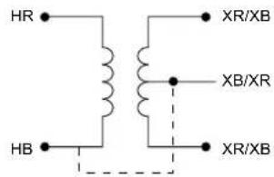
text_image
HR HB XR/XB XB/XR XR/XB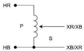
text_image
HR P S HB XR/XB XB/XRMessungen - FALSCH
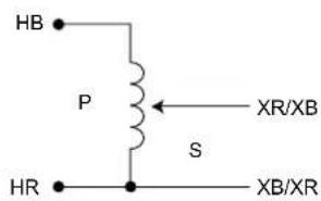
text_image
HB P XR/XB S HR XB/XR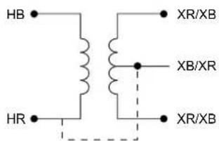
text_image
HB HR XR/XB XB/XR XR/XBtext_image
Setup English Franzicas Español Install Exit Select an option from the list below, then select the Install button. Options DataView Version 3.06.0009 Adobe Reader Database Update Hardware Upgrades Documents Description Installs the English version of DataView onto this computer. This version of DataView supports the following instruments: Ground Tester (Model 6470-8, 6471 and 6472) Megohemeter (Model 1060, 5060 and 5070) Micro-Objectmeter (Model 6240 and 6250) Power Meters (Model 8230) Power Quality Logger (Model PQL100 and PQL120) PowerPad (Model 3945 and 3945-8) PowerPad II (Model 8335) PowerPad Jr (Model 8230) Sentinel Data Logger Simple Logger II DTR Model 8510Abb. 7-1
text_image
DataView - InstallShield Wizard Select Features Select the features setup will install Select the features you want to install, and deselect the features you do not want to install QTR Ground Integrity Monitor Ground Texter Installation Texter Magichromates MicroDynamics Power Quality Logger PowerPad PowerPad II (Model 8325) PowerPad Jr Sentinel Data Logger Simple Logger II Watermates 8220 PDF-VSChange 01.57 MB of space required on the C drive 172882.03 MB of space available on the C drive Description QTR support files Install... < Back Next > CancelAbb. 7-2
text_image
DataView - InstallShield Wizard Do not connect the AEMC USB Instrument (or cable) until after the installation of the drivers and the DataView software has finished. If the AEMC USB Instrument (or cable) is connected to the computer now then disconnect it from the computer before proceeding. OKAbb. 7-3

text_image
Connection Communications port DTR Model (510. (SN 129511HKDv) Communication rate 115200 OK Cancel HelpAbb. 7-4
text_image
FTP Control Panel - Untitled FTP Control Panel: Untitled FTP Control Panel: Untitled FTP Control Panel: Untitled FTP Control Panel: Untitled FTP Control Panel: Untitled FTP Control Panel: Untitled FTP Control Panel: Untitled FTP Control Panel: Untitled FTP Control Panel: Untitled FTP Control Panel: Untitled FTP Control Panel: Untitled FTP Control Panel: Untitled FTP Control Panel: Untitled FTP Control Panel: Untitled FTP Control Panel: Unt titled FTP Control Panel: Untitled FTP Control Panel: Untitled FTP Control Panel: Untitled FTP Control Panel: Untitled FTP Control Panel: Untitled FTP Control Panel: Untitled FTP Control Panel: Untitled FTP Control Panel: Untitled FTP Control Panel: Untitled FTP Control Panel: Untitled FTP Control Panel: Untitled FTP Control Panel: Untitled FTP Control Panel: Untitled FTP Control Panel: Untitled ftp10000000000000000000000000000000000000000000000000000000000000000000000000000000000000000000000000000 FTP Control Panel: Untitled FTP Control Panel: Untitled FTP Control Panel: Untitled FTP Control Panel: Untitled FTP Control Panel: Untitled FTP Control Panel: Untitled FTP Control Panel: Untitled FTP Control Panel: Untitled FTP Control Panel: Untitled FTP Control Panel: Untitled FTP Control Panel: Untitled FTP Control Panel: Untitled FTP Control Panel: Untitled FTP Control Panel: Untitled FP1234678888888888888888888888888888888888888888888888888888888888888888888888888888888888888888888888888888Abb. 7-7
text_image
Date/Time Date 11/ 8/2010 OK Time 4:33:30 PM Cancel Synchronize with PC ClockAbb. 7-9
text_image
Run Test Test Type VT / PT CT Test Mode Ratio Cont/Ratio Test Filter Fast Normal Slow Primary 13000 Secondary 120 Test Result Measurement Date: 11/8/2010 - 4:58:21 PM Object: I Test: I Test type: VT/PT Test mode: Ratio Filter: Normal Turns ratio: 115.05:1 Deviation: 0.04 % Excitation current: 0 mA Primary voltage: 13800 V Secondary voltage: 120 V Object: I Test: I Start Save CloseAbb. 7-10
text_image
PRI :0019920 SEC :0007200Figura 4-13
OSSERVAZIONE:
text_image
X Circuito: --- H Circuito:Figura 5-3

chemical
Electrical circuit diagram showing a transformer with primary and secondary windings labeled HR/HB, HB/HR, P, S, XR/XB, XB/XR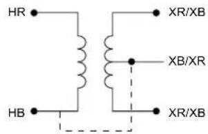
text_image
HR HB XR/XB XB/XR XR/XB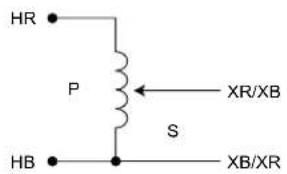
text_image
HR P S HB XR/XB XB/XRMisure - INCORRETTE
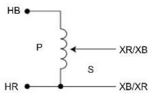
text_image
HB P XR/XB S HR XB/XR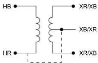
text_image
HB HR XR/XB XB/XR XR/XB6.2. COLLEGAMENTI DIFFERENZIALI
| N°di REF | -TRASFORMATORE - | TIPO XFMR | PHASE | AVVOL-GIMENTO ALTA TENSIONE | AVVOL-GIMENTO BASSA TENSIONE | RAPPORTO DI TRASFOR-MAZIONE | |
| AVVOLGIMENTO ALTA TENSIONE | AVVOLGIMENTO BASSA TENSIONE | ||||||
| 1 | 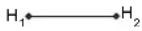 | 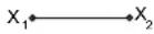 | 1 ∅ STD | 1 ∅ | H_1-H_2 | X_1-X_2 | _HV_X |
| 2 |  |  | Δ - Δ STD | A | H_1-H_3 (A) | X_1-X_3 (a) | _HV_X |
| B | H_2-H_1 (B) | X_2-X_1 (b) | |||||
| C | H_3-H_2 (C) | X_3-X_2 (c) | |||||
| 3 |  | 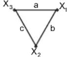 | Δ - Δ REV | A | H_1-H_3 (A) | X_1-X_3 (a) | _HV_X |
| B | H_2-H_1 (B) | X_2-X_1 (b) | |||||
| C | H_3-H_2 (C) | X_3-X_3 (c) | |||||
| 4 | 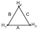 | 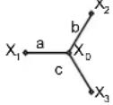 | Δ - Y STD | A | H_1-H_3 (A) | X_1-X_0 (a) | _H · [3]V_XV_X |
| B | H_2-H_1 (B) | X_2-X_0 (b) | |||||
| C | H_3-H_2 (C) | X_3-X_0 (c) | |||||
| 5 |  | 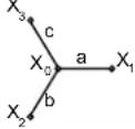 | Δ - Y REV | A | H_1-H_3 (A) | X_1-X_0 (a) | _H · [3]V_XV_X |
| B | H_2-H_1 (B) | X_2-X_0 (b) | |||||
| C | H_3-H_2 (C) | X_3-X_0 (c) | |||||
| 6 | 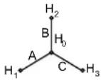 | 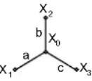 | Y - Y STD | A | H_1-H_0 (A) | X_1-X_0 (a) | _HV_X |
| B | H_2-H_0 (B) | X_2-X_0 (b) | |||||
| C | H_3-H_0 (C) | X_3-X_0 (c) | |||||
| 7 | 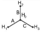 | 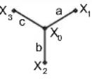 | Y - Y REV | A | H_1-H_0 (A) | X_1-X_0 (a) | _HV_X |
| B | H_2-H_0 (B) | X_2-X_0 (b) | |||||
| C | H_3-H_0 (C) | X_3-X_3 (c) | |||||
| 8 | 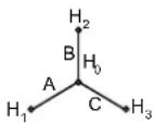 | 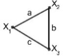 | Y - Δ STD | A | H_1-H_0 (A) | X_1-X_2 (a) | _HV_X · [3]3 |
| B | H_2-H_0 (B) | X_2-X_3 (b) | |||||
| C | H_3-H_0 (C) | X_3-X_1 (c) | |||||
| 9 | 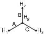 |  | Y - Δ REV | A | H_1-H_0 (A) | X_1-X_2 (a) | _HV_X · [3]3 |
| B | H_2-H_0 (B) | X_2-X_3 (b) | |||||
| C | H_3-H_0 (C | X_3-X_1 (c) | |||||
text_image
Setup English Francaes Español Install Exit Select an option from the list below, then select the Install button. Options DataView Version 3.06.0009 Adobe Reader Database Update Hardware Upgrades Documents Description Installs the English version of DataView onto this computer. This version of DataView supports the following instruments: Ground Tester (Model 6470-8, 6471 and 6472) Megohemeter (Model 1060, 5060 and 5070) Micro-Objectmeter (Model 6240 and 6250) Power Meters (Model 8230) Power Quality Logger (Model PQL100 and PQL120) PowerPad (Model 3945 and 3945-8) PowerPad II (Model 8335) PowerPad Jr (Model 8230) Sentinel Data Logger Simple Logger II DTR Model 8510Figura 7-1
text_image
DataView - InstallShield Wizard Select Features Select the features setup will install Select the features you want to install, and derived the features you do not want to install OTR Ground Integrity Monika Ground Textile Installation Textile Megohmmeter MicroDimmeter Power Quality Logger PowerPad PowerPad II (Model 8325) PowerPad Jr Sentinel Data Logger Simple Logger II Watermates 8220 PDF V6Change Description OTR support file 11.57 MB of space required on the C drive 172882.03 MB of space available on the C drive Install > Back Next > CancelFigura 7-2
text_image
DataView - InstallShield Wizard Do not connect the AEMC USB Instrument (or cable) until after the installation of the drivers and the DataView software has finished. If the AEMC USB Instrument (or cable) is connected to the computer now then disconnect it from the computer before proceeding. OKFigura 7-3

text_image
Connection Communications port DTR Model 0510. (SN 128511HKDiv) Communication rate 115200 OK Cancel HelpFigura 7-4
text_image
Date/Time Date 11/ 8/2010 OK Time 4:33:30 PM Cancel Synchronize with PC ClockFigura 7-9
text_image
Run Test Test Type Y1 / PT CT Test Mode Ratio Cont/Ratio Test Filter Post Normal Slow Primary 13000 Secondary 120 Test Result Measurement Date: 11/8/2010 - 4:58:21 PM Object: 1 Test: 1 Test type: Y1/PT Test mode: Ratio Filter: Normal Turn ratio: 115.05:1 Deviation: 0.04 % Evolution current: 0 mA Primary voltage: 13800 V Secondary voltage: 120 V Object: 1 Text 1 Start Save CloseFigura 7-10
text_image
Open Look in DTR Samples All Objects Oct 21 2010.kp Object: Test10.kp Test 1 Oct 8 2010.kp Test 2 Oct 8 2010.kp Test 3 Oct 8 2010.kp Test 4 Oct 8 2010.kp Test 5 Oct 8 2010.kp Test 6 Oct 8 2010.kp Test 7 Oct 21 2010.kp Test 8 Nov 8 2010.kp My Documents My Computer My Network File name: Test 8 Nov 8 2010.kp Files of type: DTR Data Files (*.kpc) Open as read-only Open CancelFigura 7-14
text_image
PRI :0019920 SEC :0007200Figura 4-13
OBSERVACIÓN:
text_image
Circuit X: --- Circuit H:Figura 5-3

chemical
Electrical circuit diagram showing a transformer with primary and secondary windings labeled HR/HB, HB/HR, P, S, XR/XB, XB/XR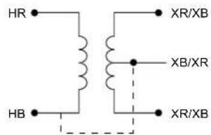
text_image
HR HB XR/XB XB/XR XR/XB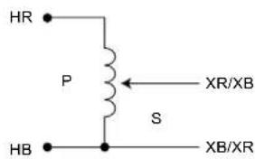
text_image
HR P S XR/XB HB XB/XRtext_image
DataView - InstallShield Wizard Select Features Select the features setup will install. Select the features you want to install and decide the features you do not want to install. DTR Ground Integrity Monika Ground Texter Installation Texter Megahmmeter MicroChrometer Power Quality Logger PowerPad PowerPad II (Model 9335) PowerPad Jh Sentinel Date Logger Sample Logger II Waltmeter 8220 PDF XChange Description DTR support files 91.57 MB of space required on the C drive 172662 (3) MB of space available on the C drive < Back Next > CancelFigura 7-2
text_image
DataView InstallShield Wizard Do not connect the AEMC USB Instrument (or cable) until after the installation of the drivers and the DataView software has finished. If the AEMC USB Instrument (or cable) is connected to the computer now then disconnect it from the computer before proceeding. OKFigura 7-3

text_image
Connection Communications port DTR Model 8510. (SN 126511HKDV) Communication rate 110,000 OK Cancel HelpFigura 7-4
text_image
Date/Time Date 11/ 8/2010 OK Time 4:33:30 PM Cancel Synchronize with PC ClockFigura 7-9
text_image
Run Test Test Type Y1 / PT CT Test Mode Ratios Cont/Ratio Test Filter Post Normal Slow Primary 13800 Secondary 120 Test Result Measurement Date: 11/8/2010 - 4:58:21 PM Object: 1 Test: 1 Test type: Y1/PT Test modes: Ratio Filter: Normal Turn ratio: 115.05x1 Deviation: 0.04 % Excitation current: 0 mA Primary voltage: 13800 V Secondary voltage: 120 V Object: 1 Test 1 Start Save CloseFigura 7-10
text_image
EBS Control Panel - Event File Edit View Inserted Help Name: Category: Component: Address: 1 Address: 2 City: State: DP: P Value: Event: ESD Model: B Event: BACT Status: Event Code 11/19/2017-8-4:43:15 PM 11/19/2017-8-4:43:32 PM 11/19/2017-8-4:43:15 PM 11/19/2017-8-4:43:30 PM 11/19/2017-8-4:43:57 PM 11/19/2017-8-4:47:07 PM 11/19/2017-8-4:47:25 PM 11/19/2017-8-4:47:30 PM 11/19/2017-8-4:47:52 PM 11/19/2017-8-4:48:54 PM Event: BACT Event: BACT Event: BACT Event: BACT Event: BACT Event: BACT Event: BACT Event: BACT Event: BACT Event: BACT Event: BACT Event: BACT Event: BACT Event: BACT Event: BACT Event: BACT Event: BACT Event: BACT Event: BACT Event: BACT Event: BCT Event: BACT Event: BACT Event: BACT Event: BACT Event: BACT Event: BACT Event: BACT Event: BACT Event: BACT Event: BACT Event: BACT Event: BACT Event: BACT Event: BACT Event: BACT Event: BACT Event: BACT Event: BACT Event: BACT Event: BUST Event: BUST Event: BUST Event: BUST Event: BUST Event: BUST Event: BUST Event: BUST Event: BUST Event: BUST Event: BUST Event: BUST Event: BUST Event: BUST Event: BUST Event: BUST Event: BUST Event: BUST Event: BUSTFigura 7-12
Unit 1 Nelson Ct - Flagship Sq - Shaw Cross Business Pk
Dewsbury, West Yorkshire - WF12 7TH
Tel: 01924 460 494 - Fax: 01924 455 328
MIDDLE EAST - Chauvin Arnoux Middle East
P.O. BOX 60-154 - 1241 2020 JAL EL DIB (Beirut) - LEBANON
Tel: (01) 890 425 - Fax: (01) 890 424
CHINA - Shanghai Pu-Jiang - Enerdis Instruments Co. Ltd
3 F, 3 rd Building - N° 381 Xiang De Road - 200081 SHANGHAI
Tel: +86 21 65 21 51 96 - Fax: +86 21 65 21 61 07
USA - Chauvin Arnoux Inc - d.b.a AEMC Instruments
200 Foxborough Blvd. - Foxborough - MA 02035
Tel: (508) 698-2115 - Fax: (508) 698-2118
http://www.chauvin-arnoux.com