BigBite 90 - Basket Klarstein - Free user manual and instructions
Find the device manual for free BigBite 90 Klarstein in PDF.

User questions about BigBite 90 Klarstein
0 question about this device. Answer the ones you know or ask your own.
Ask a new question about this device
Download the instructions for your Basket in PDF format for free! Find your manual BigBite 90 - Klarstein and take your electronic device back in hand. On this page are published all the documents necessary for the use of your device. BigBite 90 by Klarstein.
USER MANUAL BigBite 90 Klarstein
text_image
QR code image containing encoded data, no visible human-readable textINHALTSVERZEICHNIS
natural_image
Diagram of airflow around a mechanical component with directional arrows indicating movement (no text or symbols)natural_image
Diagram of a brick wall with a chimney and outlet, showing airflow direction (no text or symbols)natural_image
Simple line drawing of a rectangular box and a small 3D box with internal arrows, no text or symbols present.natural_image
Technical line drawing of a mechanical component with multiple views and mounting holes (no text or symbols)| L1 = weiß L2 = rot L3 = grün | ||
| L4 = blau L5 = gelb L6 = lila | ||
| L7 = orange L8 = türkis L9 = | grün-gelb |
text_image
Technical diagram showing a mechanical assembly with a droplet and labeled parts, including numbered annotations.natural_image
Symbol of a trash bin crossed with a diagonal line, representing no waste or discharge (no text or labels)Berlin Brands Group UK Limited
PO Box 42
272 Kensington High Street
London, W8 6ND
United Kingdom
Congratulations on the purchase of your device. Please read the following instructions carefully and follow them to prevent potential damage. We accept no liability for damage caused by disregarding the instructions and improper use. Please scan the QR code to access the latest operating instructions and further information about the product.

text_image
QR code image containing encoded data, no visible human-readable textCONTENTS
Safety Instructions 24
Installation 26
Installing the activated carbon filter 30
Control Panel 31
Key Functions 31
Device Control by Smartphone 33
Cleaning and Maintenance 35
Replacing the lighting 35
Troubleshooting 37
Product data sheet 38
Notes on environmental protection 39
Dismantling and disposal of the hood 39
Disposal Considerations 40
Declaration of Conformity 40
TECHNICAL DATA
| Article number | 10045552, 10045553, 10045554, 10045555 |
| Power supply 220-240 V ~ 50/60 Hz | |
| Note: You can also purchase an activated carbon filter for this cooker hood under item number 10032844. | |
SAFETY INSTRUCTIONS
- Read all instructions carefully before use and keep this user manual in a safe place for future reference.
- The installation work may only be carried out by an electrician or a qualified person. Before using the cooker hood, make sure that the voltage (V) and frequency (Hz) indicated on the cooker hood correspond to the voltage and frequency of the power supply in your household.
- We accept no liability for damage caused by improper use or installation.
• Children under 8 years of age must not use the cooker hood. - The appliance is intended for use in the home and similar environments only. It is not intended for commercial use.
- Clean the appliance and the filter regularly to keep the appliance working efficiently.
• Always disconnect the power plug from the socket before cleaning. - Clean the appliance exactly as indicated in the operating instructions.
- Do not use an open fire under the extractor hood.
- If the unit is not functioning normally, contact the manufacturer or a specialist company.
- Children from the age of 8 years and mentally, sensory and physically impaired persons may only use the device if they have been informed in detail about the functions and safety precautions by a supervisor responsible for them beforehand and understand the associated risks.
- If the power cord is damaged, it must be replaced by the manufacturer, an authorised specialist company or a similarly qualified person.
- If the cooker hood is used with cookers that burn gas or other fuels, there must be adequate ventilation in the room.
- Do not flambé under the extractor hood.
- Caution: The surface of the unit may become hot during operation.
Important instructions for installation
- The air must not be discharged into a flue used for extracting flue gases from gas or other fuels (does not apply to appliances that only return the air to the room).
- Observe all regional regulations for the installation of ventilation systems.
Important notes on exhaust air operation
WARNING
Danger of poisoning from recirculated exhaust gases! Do not operate the appliance in extract air mode if it is operated together with a room air-dependent fi replace and sufficient air circulation is not guaranteed.
Room air-dependent fi replaces such as gas, oil, wood or coal heaters, boilers or instantaneous water heaters draw the air from the room and lead it outdoors through an exhaust pipe or chimney. In extract air mode, air is extracted from the kitchen and neighbouring rooms. Without sufficient supply air, negative pressure is created. Toxic gases from the chimney or exhaust pipe can be sucked back into the living rooms.
- Make sure that sufficient fresh air supply is guaranteed and that the air can circulate.
- A supply air/exhaust air wall box is not sufficient to ensure compliance with the limit value.
Safe operation is only possible if the negative pressure at the location of the fi replace does not exceed 4 Pa (0.04 mbar). This can be achieved if the air required for combustion can flow in through non-closable openings in doors and windows in conjunction with a supply air / exhaust air wall box. In any case, have a master chimney sweep advise you and assess the entire ventilation system of the house. If necessary, they can tell you the necessary measure for ventilation.
If the cooker hood is used exclusively in recirculation mode, operation is possible without restriction.
Important note on dismantling the unit
- Disassembly is the same as installation/assembly in reverse order.
- Have a second person help you during disassembly to avoid injury.
INSTALLATION
Preparation
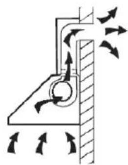
If you have an extractor to the outside, you can install the extractor hood as shown in the picture on the right. The flue should have a diameter of at least 150 mm and be made of enamel, aluminium or a flexible, heat-resistant tube.
- Switch off the device before installation and pull the power plug out.
- The extractor hood should be placed at a height of 65-75 cm above the hob.
natural_image
Diagram of airflow around a mechanical component with directional arrows indicating movement (no text or symbols)Installation with exhaust air
Note: Observe the safety instructions for operating the unit when the air is discharged to the outside. If the cooker hood is in operation at the same time as an appliance that draws its energy from a source other than electricity, the negative pressure in the room must not exceed 4 Pa (4 x 10⁻⁵ bar).
Installation with convection function
If you do not have an outside vent, install an activated carbon filter before using the unit.
Important notes for the installation of exhaust air pipes
The following rules must be strictly observed to guarantee optimum air extraction: Failure to follow these instructions will reduce the performance and increase the noise level of the cooker hood.
- Lay the exhaust pipe as short and straight as possible.
- Do not use a smaller exhaust pipe and do not constrict it.
- When using flexible pipes, the pipe must always be installed tightly in order to minimise pressure loss.
- All installation work must only be carried out by a qualified electrician or a qualified person.
-
Do not connect the hood's exhaust pipe to an existing ventilation system that is being used for another device, such as a fireplace.
-
The angle of the bend of the exhaust air pipe should not be less than 120°. Align the pipe horizontally. Alternatively, the pipe should go up from the starting point and be led to an outer wall.
• After installation, make sure that the cooker hood is horizontal in order to prevent grease from collecting on one side. - Make sure that the exhaust duct selected for installation complies with the relevant standards and is fire resistant.
Installation of the sloping hood

text_image
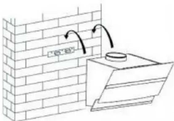
Borehole Dowel Holder Screws (4 mm x 30 mm)Drill 3 x 8 mm holes for the wall bracket. Fix the wall bracket to the wall with the supplied dowels and screws.
natural_image
Diagram of a brick wall with a chimney and outlet, showing airflow direction (no text or symbols)Lift the extractor hood and hang it on the wall bracket.
flowchart
graph TD
    A["1: Raw Material"] --> B["2: Process Step"]
    B --> C["3: Intermediate Product"]
    C --> D["4: Final Product"]
    D --> E["5: Final Product"]
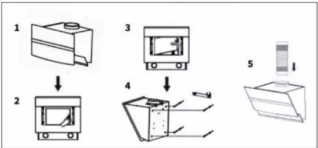
- Open the glass plate (1) and remove the metal grease filter (2-3).
- Mark the four mounting holes on the inside of the hood.
- Remove the extractor hood again. Drill four 8 mm diameter holes in the wall at the marked locations and insert the dowels into the holes.
- Hang the extractor hood on the wall bracket and fasten it to the dowels with the screws from the inside of the hood (4).
- Connect the exhaust hose to the outlet (5).
Chimney installation
text_image
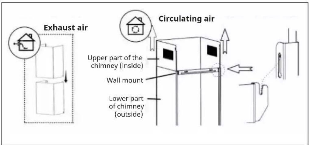
Exhaust air Circulating air Upper part of the chimney (inside) Wall mount Lower part of chimney (outside)- Slide the upper chimney section into the lower chimney section. Pay attention to the position of the ventilation slots - depending on the use for exhaust or recirculation (see illustration).
- Attach the lower wall bracket to the lower part of the chimney.
natural_image
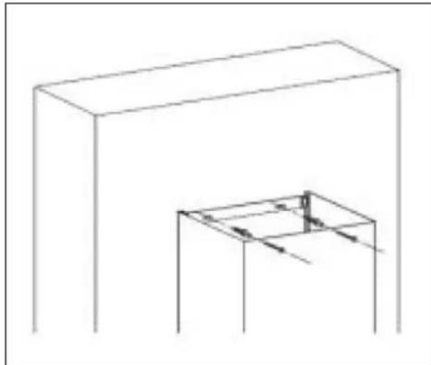
Simple line drawing of a rectangular box and a small 3D cube with internal arrows, no text or symbols present.- Place the chimney on the hood.
• Mark the mounting holes for the lower wall bracket on the wall and pre-drill at the marked locations.
- Fix the lower wall bracket to the wall with 2 dowels and screws (4 mm x 30 mm).
text_image
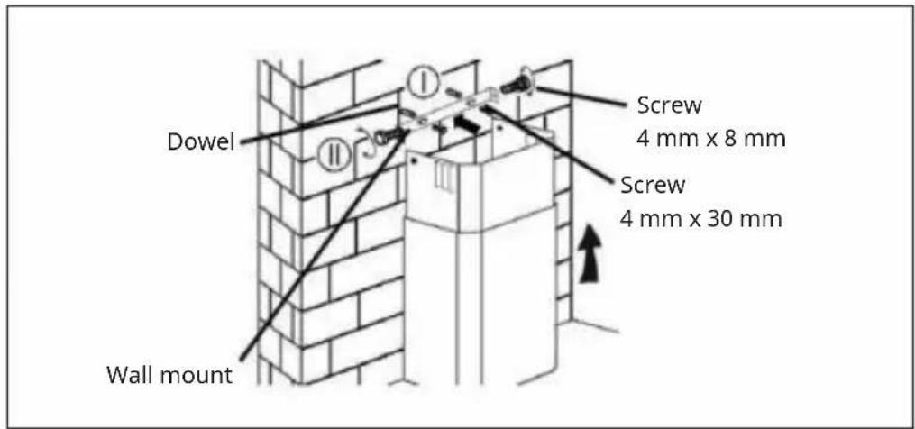
Dowel Wall mount Screw 4 mm x 8 mm Screw 4 mm x 30 mm- Pull out the upper part of the chimney to the desired height.
- Mark the mounting holes for the upper wall bracket on the wall and pre-drill at the marked locations.
- Fix the upper wall bracket to the drilled positions on the wall using 2 dowels and 2 screws ST4 x 30 mm.
- Fasten the upper part of the chimney to the wall bracket with 2 screws ST4 x 8 mm.
INSTALLING THE ACTIVATED CARBON FILTER
Note: An activated carbon filter is only required for recirculation mode. If you are using the hood in extraction mode, remove the activated carbon filter.
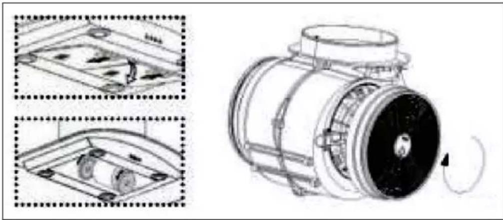
natural_image
Technical line drawing of a mechanical component with multiple views and mounting features (no text or symbols)Remove the metal grease filter. The activated carbon filter is divided into two and is mounted on the right and left of the motor. Check that the teeth correspond with the direction of rotation of the respective side. Turn the activated carbon filter onto the motor housing (normally clockwise). Replace the metal grease filter.
CONTROL PANEL
 |  |  |  |  |
| 1 | 2 | 3 | 4 | 5 |
| 1 POWER button (switch on/off the device) | ||||
| 2 Speed | ||||
| 3 Display | ||||
| 4 Light (on /off) | ||||
| 5 WiFi (WLAN icon) | ||||
KEY FUNCTIONS
On/Off
Press the ON/OFF button briefly to switch on the cooker hood. When you switch on the unit for the first time, the fan runs at speed 1. When you switch off the unit, it remembers the last speed set.
Setting the speed
Briefly press the SPEED button several times to set the desired speed: Level 1 (low) > Level 2 (medium) > Level 3 (high).
Setting the switch-off delay
When the unit is in standby mode, press and hold the SPEED + LIGHT keys simultaneously to set the fan to turn off with a 5 minute delay. The current speed flashes in the display and the time is counted down. After the time has elapsed, all keys will dim down while the display continues to flash and a signal sounds. Press any key or wait 5 seconds to switch to standby mode. To cancel the delay, press and hold the SPEED + LIGHT keys simultaneously during the countdown.
Light on/off
Briefly press the LIGHT key to switch the light on. Press the key again to switch the light off.
Setting the light color
Press and hold the light key to set the light color. The display shows [0]. Now briefly press the speed key several times to adjust the light color from [L1] to [L9]:
| L1 = white L2 = red L3 = green | ||
| L4 = blue L5 = yellow L6 = purple | ||
| L7 = orange L8 = cyan L9 = green-yellow |
After setting the desired color, long press the LIGHT button again to complete the setting.
Enable WIFI
In standby mode, long press the WIFI button to activate the WIFI function. The WIFI icon will start flashing. Set up the connection as described in the chapter „Device Control by Smartphone“. As soon as the connection is successful, the WIFI symbol lights up continuously. If no connection is established within 3 minutes, the WIFI icon stops flashing and the device automatically switches to standby mode.
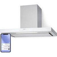
DEVICE CONTROL BY SMARTPHONE
If you integrate the device into your home WiFi, you can conveniently operate it via the associated Klarstein app. The app not only allows you to remotely control the device via your smartphone, but also gives you access to recipes and additional information.
Follow these steps to connect your smartphone to your Klarstein device:
- Download the Klarstein app first by scanning the QR code with your smartphone (see below), or download it directly from App Store or Google Play.
- Make sure your smartphone is connected to the same WiFi network that your Klarstein device is to be connected to.
- Open the Klarstein app.
- Sign in to your account. If you do not have an account, sign up in the Klarstein app.
- Follow the instructions from the app.
App Download
Use the scan function of your smartphone to scan the QR code and save the app on your smartphone.
Note: The app provides further information on how to use the app and help on how to connect to your device as soon as you open it for the first time.
| iOS Android | |
Troubleshooting connection problems
If your Klarstein device cannot be found in the WLAN, check the following:
- The device is not plugged in. Make sure that your device is plugged into an electric socket.
- The device is not in pairing mode. Make sure that the WiFi indicator (LED) on the smart device control panel is blinking as described in the 'Reset WiFi settings' instruction of your smart device (instructions are usually available on device connection process).
- The WiFi access point does not operate on 2.4 GHz. Make sure that your access point operates on 2.4 GHz band and you have a separate SSID on 2.4 GHz band. If you are not sure about the operating band of your access point, please contact your internet provider company.
Important: please note that if your WiFi router is dual band - operating on both 2.4 GHz and 5 GHz band - you need to separate the SSIDs for each band and use the 2.4 GHz SSID for connection.
-
Firewall settings of your WiFi network; the firewall setting of your WiFi network may not allow the Klarstein app to configure the WiFi settings on your smart device. Please make sure that you are not using a public WiFi network, e.g. airports, dormitories, companies, etc.
-
Different credentials used in smartphone and the app. Make sure that the WiFi credentials entered in the Klarstein app are the same as the ones that your smartphone is connected to.
Following the above mentioned points, if your smart device still fails to connect to the app, please contact us via email for support: appsupport@go-bbg.com
CLEANING AND MAINTENANCE
Switch off the extractor hood and pull the plug out of the socket before cleaning and maintenance. The outer surfaces are susceptible to scratches and stains. Therefore, do not use scouring agents for cleaning and wipe away residues of alkaline or acidic substances (lemon juice, vinegar) immediately after cleaning.
Stainless steel surfaces
The stainless steel must be cleaned regularly to ensure a long service life. Use stainless steel cleaner for this purpose. Always wipe along the grain of the stainless steel to prevent criss-crossing scratch marks.
Control panel interface
The control panel can be cleaned with a damp cloth and mild dishwashing detergent. Before cleaning, make sure the cloth is clean and well wrung out. Use a dry, soft cloth to remove excess moisture after cleaning.
Monthly cleaning of the grease filters
Clean the filter every month to avoid a fire hazard. The filter collects grease, smoke and dust and thus influences the efficiency of the cooker hood. If the filter is not cleaned, grease residues will collect there. Clean the filter with water and a little washing-up liquid and let it air dry afterwards.
REPLACING THE LIGHTING
Please note:
- The lighting may only be replaced by a qualified electrician.
- Before opening the device, unplug all power connections.
• Always allow the lighting to cool down before replacing it.
• Always use gloves or a cloth to avoid direct contact with your hands. - Direct contact can shorten the life of the lighting.
Replacing E14 bulb
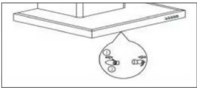
text_image
Technical diagram showing a mechanical assembly with a droplet and labeled parts, including numbered annotations.Switch off the device immediately and pull the power plug out. Remove the light cover by unscrewing the 2 screws. Unscrew the light bulb. Replace with a bulb of the same type and wattage.
Replacing the LED light
- Switch off the device immediately and pull the power plug out.
- Locate the location of the lamp brackets.
- On some models you need to remove the grease filters to find the lamp holders. On some other models, the lamp holders are covered by a light screen. Unscrew the light screen before replacing.
- Remove the screws on the LED board and brackets, separate and carefully insert the new light.
| For round LED lights For LED lights with light screen | |
Note: Remember to reassemble everything after replacing the new lamp and fix all screws in the same position. Always replace the light with the same type and amperage.
TROUBLESHOOTING
| Problem Potential cause | Solution | |
| The light turns on but the motor does not run. | The ventilation is blocked. | Remove the blockage. |
| The capacitor is broken. Have the capacitor replaced. | ||
| The motor is broken. Have the motor replaced. | ||
| The motor smells strange. | Have the motor replaced. | |
| The light is off and the motor does not run. | The light is broken. Have the light replaced. | |
| The plug is loose. Plug the power plug securely into the wall socket. | ||
| The housing vibrates. The | rotor blade of the fan is damaged. | Replace the blade. |
| The motor is not firmly seated. | Fasten the motor. | |
| The casing is loosely hanging. | Fasten the housing. | |
| The air is not being properly extracted. | The distance between the cooker and the extractor hood is too far. | Reduce the distance. |
| Too much air circulation through open windows and doors. | Make sure that there is no draught. | |
PRODUCT DATA SHEET
Information according to Regulation (EU) No 65/2014
Measurement and calculation methods according to EN 61591:1997+A1:2006+A2:2011+A11:2014+A12:2015
| Article number | 10045552, 10045553, 10045554, 10045555 | ||
| Designation Symbol Value Unit | |||
| Annual energy consumption AEC | hood | 9.7 kWh/year | |
| Energy efficiency class A++ | |||
| Fluid-dynamic efficiency FDE | hood | 24.3 | |
| Fluid dynamic efficiency class B | |||
| Lighting efficiency LE | hood | 32 Lux/W | |
| Lighting efficiency class A | |||
| Grease separation efficiency GFE | hood | 68.7 % | |
| Class for grease separation efficiency | D | ||
| Air flow at minimum and at maximum speed in normal operation, excluding operation on the intensive or fast speed setting | 176.0/246.9 m3/h | ||
| Air flow when operating on the intensive or fast speed setting | - | ||
| A-rated airborne noise emissions at minimum and maximum available speed during normal operation | 49/57 dB | ||
| A-rated airborne noise emissions during operation at the intensive or high-speed stage | - | dB | |
| Power consumption in off-mode | P_O | 0.44 W | |
| Power consumption in standby mode | P_S | - | W |
| Contact details | Chal-Tec GmbH, Wallstraße 16, 10179 Berlin, Germany. | ||
NOTES ON ENVIRONMENTAL PROTECTION
- Make sure there is sufficient air supply during cooking so that the cooker hood can work efficiently and with low operating noise.
- Adjust the fan speed to the amount of steam produced while cooking. Use the intensive mode only when necessary. The lower the fan speed, the less energy is consumed.
- If large amounts of steam are produced when cooking, select a higher fan speed in time. If the cooking steam has already spread throughout the kitchen, the cooker hood must be operated for longer.
- Switch off the cooker hood when it is no longer needed.
- Switch off the lighting when it is no longer needed.
- Clean the filter at regular intervals and replace it if necessary to increase the effectiveness of the ventilation system and prevent fire hazards.
- Always put the lid on when cooking to reduce cooking steam and condensation.
DISMANTLING AND DISPOSAL OF THE HOOD
- Make sure that the exhaust hood is completely switched off.
- Pull the plug out of the socket.
- Remove the hood from the wall or cabinet.
- Remove the filter. Dispose of the filters at a collection point for the recycling of waste electrical and electronic equipment.
- Remove the motor. Dispose of the motor at a collection point for the recycling of waste electrical and electronic equipment.
- Dispose of the rest of the exhaust hood at your local recycling centre.
DISPOSAL CONSIDERATIONS
natural_image
Symbol of a trash bin crossed with a diagonal line, representing no waste or discharge (no text or labels)If there is a legal regulation for the disposal of electrical and electronic devices in your country, this symbol on the product or on the packaging indicates that this product must not be disposed of with household waste. Instead, it must be taken to a collection point for the recycling of electrical and electronic equipment. By disposing of it in accordance with the rules, you are protecting the environment and the health of your fellow human beings from negative consequences. For information about the recycling and disposal of this product, please contact your local authority or your household waste disposal service.
DECLARATION OF CONFORMITY

text_image
CE UK CAManufacturer:
Chal-Tec GmbH, Wallstrasse 16, 10179 Berlin, Germany.
Importer for Great Britain:
Berlin Brands Group UK Limited
PO Box 42
272 Kensington High Street
London, W8 6ND
United Kingdom
Hereby, Chal-Tec GmbH declares that the radio equipment type BigBite is in compliance with Directive 2014/53/EU. The full text of the EU declaration of conformity is available at the following internet address: use.berlin/10045555
For Great Britain: Hereby, Chal-Tec GmbH declares that the radio equipment type BigBite is in compliance with the relevant statutory requirements. The full text of the declaration of conformity is available at the following internet address: use.berlin/10045555
Estimado cliente:
text_image
QR code image containing encoded data, no visible human-readable textÍNDICE
natural_image
Diagram of airflow around a mechanical component with directional arrows indicating movement (no text or symbols)natural_image
Diagram of a brick wall with a chimney and outlet, showing airflow direction (no text or symbols)natural_image
Simple line drawing of a rectangular box with a smaller 3D cube structure below, no text or symbols present.natural_image
Technical line drawing of a mechanical component with multiple views and mounting features (no text or symbols)text_image
Technical diagram showing a mechanical assembly with a droplet and labeled parts, including numbered annotations.natural_image
Symbol of a trash bin crossed with a diagonal line, no text or numbers presentBerlin Brands Group UK Limited PO Box 42
272 Kensington High Street
London, W8 6ND
United Kingdom
Cher client, chère cliente,
text_image
QR code image containing encoded data, no visible human-readable textSOMMAIRE
natural_image
Diagram of airflow around a mechanical component with directional arrows indicating movement (no text or symbols)natural_image
Diagram of a brick wall with a chimney and outlet, showing airflow direction (no text or symbols)natural_image
Simple line drawing of a rectangular box and a small 3D cube with internal arrows, no text or symbols present.natural_image
Technical line drawing of a mechanical component with multiple views and mounting features (no text or symbols)text_image
Technical diagram showing a mechanical assembly with a droplet and labeled parts, including numbered annotations.FICHE DE DONNÉES PRODUIT
natural_image
Symbol of a trash bin crossed with a diagonal line, no text or numbers presentDÉCLARATION DE CONFORMITÉ

text_image
CE UK CAFabricant :
Chal-Tec GmbH, Wallstraße 16, 10179 Berlin, Allemagne.
Berlin Brands Group UK Limited PO Box 42 272 Kensington High Street London, W8 6ND United Kingdom
text_image
QR code image containing encoded data, no visible human-readable textINDICE
natural_image
Diagram of airflow around a mechanical component with directional arrows indicating movement (no text or symbols)natural_image
Diagram of a brick wall with a chimney and outlet, showing airflow direction (no text or symbols)natural_image
Simple line drawing of a rectangular box and a small 3D cube with internal arrows, no text or symbols present.natural_image
Technical line drawing of a mechanical component with multiple views and mounting features (no text or symbols)text_image
Technical diagram showing a mechanical assembly with a droplet and labeled parts, including numbered annotations.natural_image
Symbol of a trash bin crossed with a diagonal line, no text or labels presentBerlin Brands Group UK Limited PO Box 42 272 Kensington High Street London, W8 6ND United Kingdom