SERBATOIO 500 Kg - Boiler EDILKAMIN - Free user manual and instructions
Find the device manual for free SERBATOIO 500 Kg EDILKAMIN in PDF.


| Product type | Pellet tank |
| Brand | Edilkamin |
| Model | SERBATOIO 500 Kg |
| Capacity | 500 kg of wood pellets |
| Power supply | 230 V +/- 10%, 50 Hz |
| Motor gearbox power (no load) | 70 W |
| Motor gearbox power (under load) | 120 W |
| Motor thermal protection | 130 °C |
| Protection fuse | 4 A / 250 V |
| Fuel type | Certified wood pellets |
| Material | Steel (metal body) |
| Use | Storage and automatic feeding of a pellet boiler |
| Features | Automatic screw feeder filling, pellet level detection, electronic controller with display |
| Installation | In a dry, covered location; grounding mandatory |
| Safety | Motor thermal protection, fuse, low-level sensor |
| Maintenance | Check for obstructions in the conveyor pipe, clean pellet dust, inspect electrical connections |
| Included accessories | Loading hose, fittings, electronic controller, level probes |
| Compatibility | Edilkamin pellet boilers or others with suitable interface |
| Repairability | Spare parts available: motor, electronic board, sensors, screw auger |
Frequently Asked Questions - SERBATOIO 500 Kg EDILKAMIN
User questions about SERBATOIO 500 Kg EDILKAMIN
0 question about this device. Answer the ones you know or ask your own.
Ask a new question about this device
Download the instructions for your Boiler in PDF format for free! Find your manual SERBATOIO 500 Kg - EDILKAMIN and take your electronic device back in hand. On this page are published all the documents necessary for the use of your device. SERBATOIO 500 Kg by EDILKAMIN.
USER MANUAL SERBATOIO 500 Kg EDILKAMIN
natural_image
3D rendering of a concrete enclosure with black structural supports and a small display unit (no text or symbols visible)UK TANK 500 Kg, Installation, use and maintenance p. 12
F RÉSERVOIR 500 Kg, Installation, usage et maintenance p. 22
natural_image
Two simple L-shaped metal lines labeled A, no text or symbols presentFASE 1:
FASE 2:
ASSEMBLAGGIO DEL TELAIO
FASE 5:
natural_image
3D diagram of a stepped metal profile with labeled points D and E (no text or symbols beyond labels)FASE 3:
natural_image
3D diagram of a mechanical part with labeled section 'G' (no other text or symbols)FASE 6:
natural_image
3D diagram of a mechanical housing or enclosure with labeled components H (no text or symbols beyond labels)FASE 7:
natural_image
3D diagram of a mechanical device with labeled components (T), showing internal structure and handle (no text or symbols beyond labels)FASE 11:
FASE 12:
natural_image
3D diagram of a transparent rectangular device with internal components and labeled parts (t, j, s), no readable text or symbols beyond labels.FASE 13:
natural_image
3D diagram of a cube with an open lid and a labeled corner (no text or symbols)natural_image
Close-up of a pipe joint with a rectangular inset labeled 'O' and 'Foto 1' (no other text or symbols visible)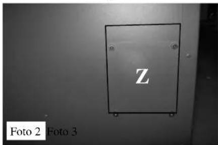
natural_image
Simple hand-drawn oval shape on a textured gray background, labeled 'Foto 8' in the corner (no other text or symbols)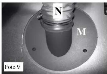
MONTAGGIO COMPONENTI
natural_image
Close-up of a white cable with a small square clip attached, mounted on a wall (no text or symbols visible)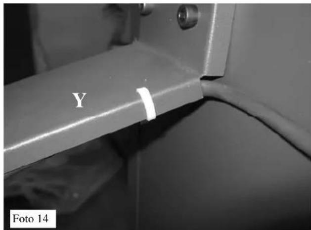
natural_image
Close-up of a metallic mechanical component with threaded connectors and a circular base, labeled 'Foto 15' in the corner (no other text or symbols visible)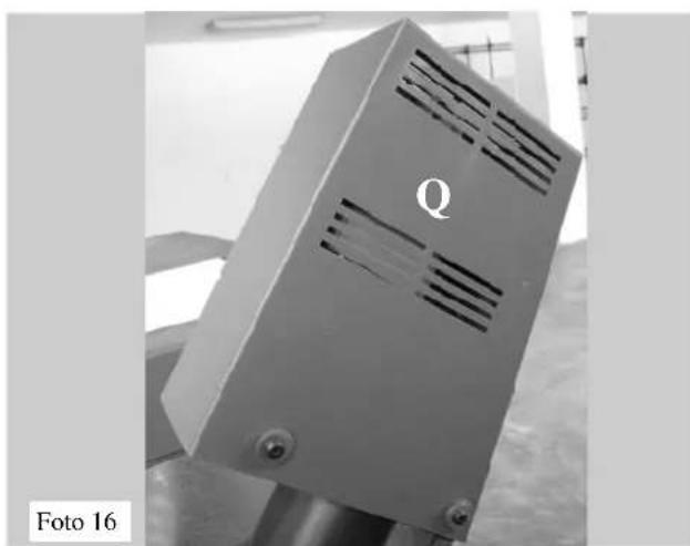
natural_image
Metallic industrial component with ventilation slots and mounting feet, labeled 'Q' (no readable text or symbols beyond label)COLLEGAMENTI ELETTRICI
natural_image
Mechanical assembly diagram showing a connector with bolts and a flange, labeled 'Foto 17' (no text or symbols on the diagram itself)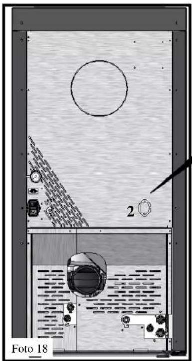
natural_image
Interior layout diagram of a water tank with circular tank, pressure gauges, and control panel (no text or symbols)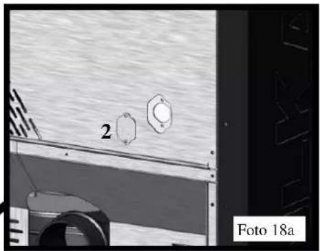
natural_image
Exterior view of a vehicle or industrial facility with two circular components and a numbered label '2' (no readable text or symbols beyond labels)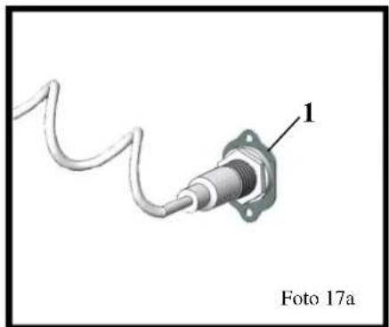
natural_image
Close-up of a mechanical component with a coiled cable and labeled part 1, no readable text or symbols beyond label
natural_image
Technical diagram showing a mechanical assembly with a numbered component and a labeled section (no readable text or symbols)natural_image
Electronic component with labeled plate and wiring, no readable text or symbols beyond labels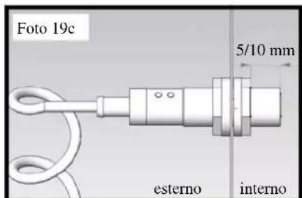
natural_image
Electronic component with labeled pins and wiring, no readable text or symbols beyond labels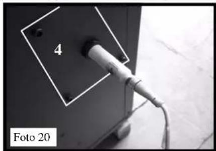
natural_image
Close-up of a plug inserted into a wall socket, labeled '4' and 'Foto 20' (no other text or symbols visible)fig. 25
fig. 29
ALLARMI
- 2006/42/EC
- 2006/95/EC
- 2004/108/EC
Congratulations and thank you for choosing our product.
Please read this document carefully before you use this product in order to obtain the best performance in complete safety.
For further details or assistance, please contact the DEALER where you purchased the product or visit our website www.edilkamin.com. and click on DEALERS.
Note: THE PRODUCT MUST BE INSTALLED IN A COVERED, HUMIDITY-FREE AREA IN ORDER TO PREVENT PROBLEMS WITH THE ELECTRICAL EQUIPMENT AND TO ENSURE THE INTEGRITY OF THE PELLETS
WE RECOMMEND USING ONLY CERTIFIED PELLETS WHICH GUARANTEE THE QUALITY OF THE PRODUCT. USE OF POOR QUALITY PELLETS CAN AFFECT OR DAMAGE THE NORMAL OPERATION OF THE EQUIPMENT.
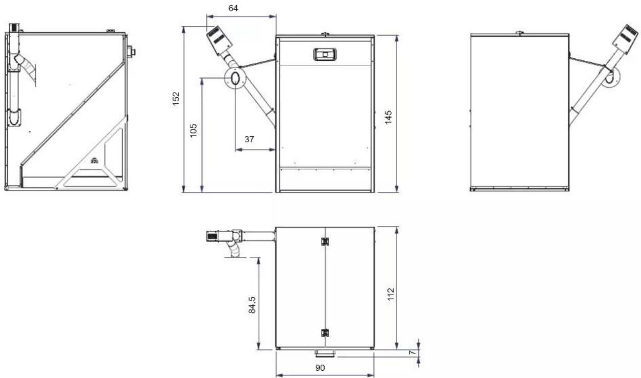
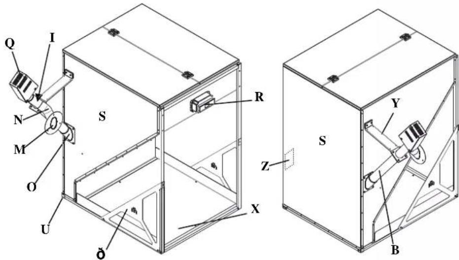
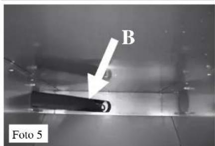
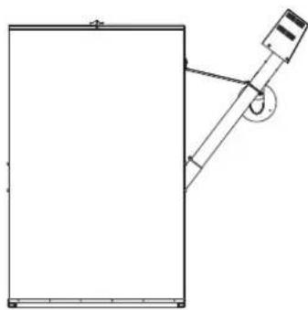
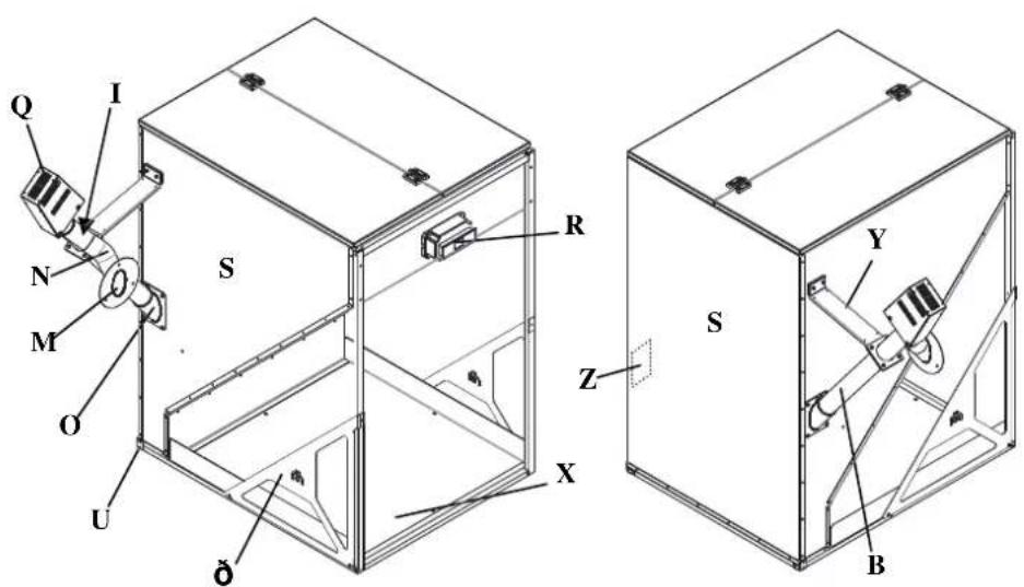
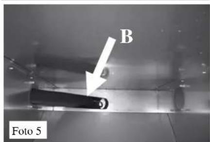
B = feeder tube (optional)
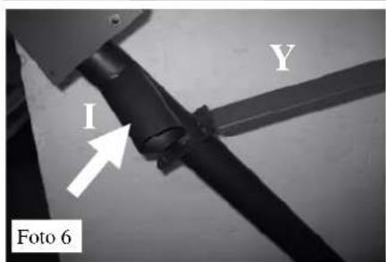
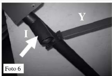
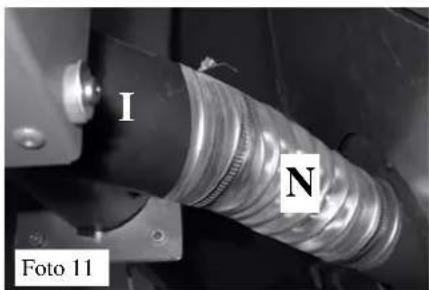
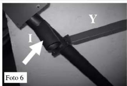
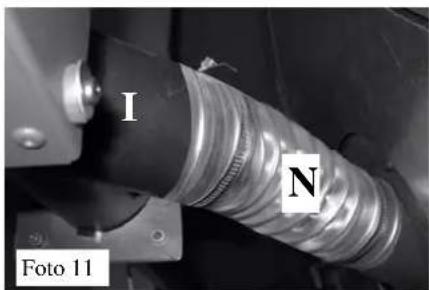
I = conveyor tube (optional)
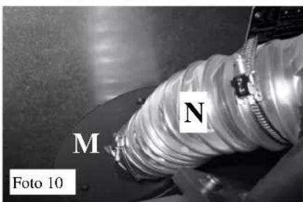
M = flexible pipe connection flange (optional)
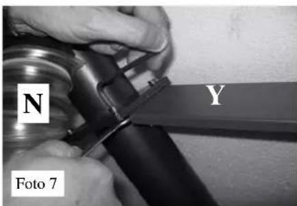
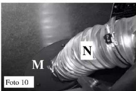
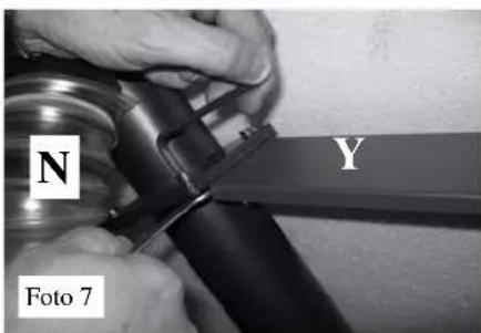
N = flexible pipe (optional)
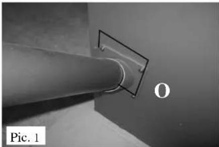
O = feeder tube connection
Q = gear motor casing (optional)
R = electronic regulator
S = tank body
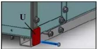
U = stop plate
Z = closing plate
X = pellet bags storage compartment
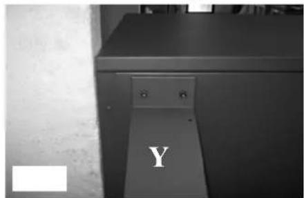
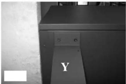
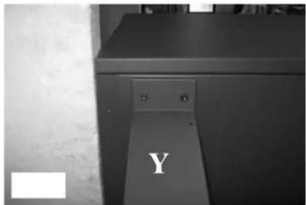
Y = feeder tube support
0 = side reinforcement
METALLIC BODY ASSEMBLY
LIST OF COMPONENTS:
• A angular shoulder elements in circular hollow section
• C cross girders
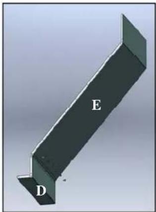
• D inclined wall
- E angular profile
- F right lateral walls
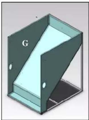
• G left lateral walls
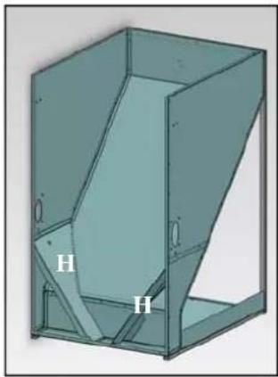
• H slides - K rear wall
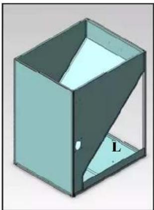
• L shelf
• = side reinforcement
- O feeder tube coupling
• T plastic caps
• U stop plates
• J-V-V1-V2 screws
natural_image
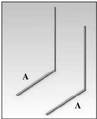
Two simple 3D L-shaped metal profiles labeled A, no text or symbols presentPHASE 1:
Position the angular shoulder elements in hollow section (A) parallel to one another
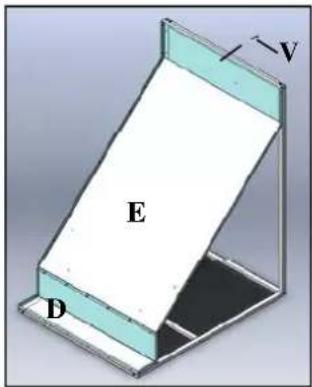
PHASE 4:
Rest the inclined wall (D-E) against the frame and use the supplied 6.3 x 45 (V) self-tapping screw to secure it to the centre of the upper cross girder.
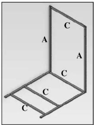
PHASE 2:
ASSEMBLING THE FRAME
Use the supplied 6.3 x 45 self-tapping screws to fasten the cross girders (C) to the two angular shoulder elements in hollow section (A).
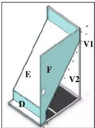
PHASE 5:
Couple the right lateral wall (F) to the inclined wall (D-E): fasten it to the shoulder element in hollow section using the two supplied 6.3 x 45 self-tapping screws (V1), and to the inclined wall using the 24 supplied 6.3 x 19 screws (V2).
natural_image
3D diagram of a stepped metal profile with labeled points D and E (no text or symbols beyond labels)PHASE 3:
Use the supplied 6.3 x 45 self-tapping screws to fasten the inclined wall (E) to the angular profile (D).
natural_image
3D diagram of a mechanical part with labeled section 'G' (no other text or symbols)PHASE 6:
Couple the left lateral wall (G) using the same procedure employed for right wall.
METALLIC BODY ASSEMBLY
natural_image
3D technical drawing of a mechanical part with labeled sections H (no text or symbols beyond labels)PHASE 7:
Insert the slides (H) and fasten them using the supplied 6.3 x 19 self-tapping screws
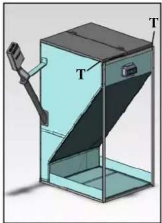
natural_image
3D diagram of a mechanical device with labeled components (T), showing internal structure and mounting bracket (no text or symbols beyond labels)PHASE 11:
Insert the plastic caps (T) at the ends of the shoulder elements and press them all the way in (use a hammer is necessary, taking care to strike the caps squarely in the centre in order to avoid damaging them). Position the cover by coupling the centring pins with the holes on the folds of the walls.
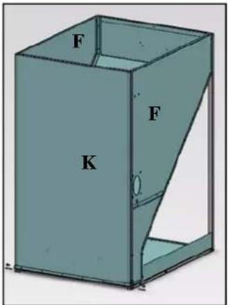
PHASE 8:
Position the rear wall (K) so that the vertical folds are on the outside of the side walls (F), and fasten them using the supplied 6.3 x 19 self-tapping screws.
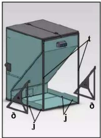
PHASE 12:
- Remove the screws on the tubular angle shoulders (t). - Fit the two side reinforcements ( ) to the tubular angle shoulders in line with the holes (t) using the screws removed previously (t) and the M 6x40 screws (j) provided.
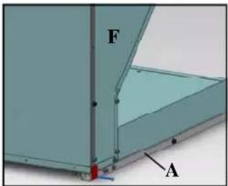
PHASE 9:
Secure the hollow sections (A) to the side walls (F) using the stop plates (U) and the supplied M6x50 screws and nuts.
natural_image
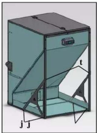
3D diagram of a mechanical device with labeled components (t, j, A) and internal structure (no text or symbols beyond labels)PHASE 13:
- Fit the same side reinforcements (V) to the horizontal base cross pieces as well in line with the holes (J), using the M6x40 screws provided.
PHASE 10:
Position the shelf (L) in the space between the hollow sections, and fasten it using the two supplied 4.8 x 13 screws
natural_image
3D diagram of a geometric container with an open lid and a labeled corner (no text or symbols)MOUNTING THE COMPONENTS OPTIONAL
LIST OF COMPONENTS:
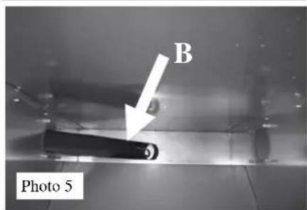
B = feeder tube
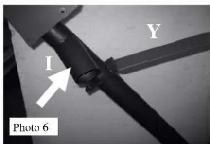
I = conveyor tube
M = flexible pipe connection flange
N = flexible pipe
O = feeder tube connection (supplied)
P = grounding cable
R = electronic regulator
Z = closing plate
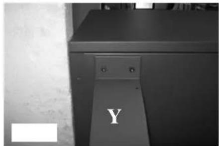
Y = feeder tube support (supplied)
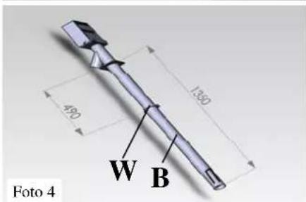
W = ring
- Install the feeder tube connection (O - supplied) on the tank body (on the side where the boiler will be located); securing it with 4 M6 screws (Pic. 1).
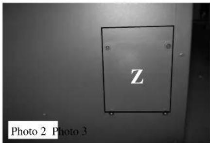
- On the opposite side (in the symmetrical position) install the closing plate (Z supplied) securing it will 4 M6 screws (Pic. 2).
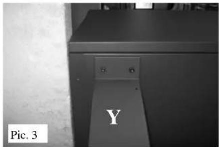
- Position the feeder tube support (Y - supplied) and fasten it to the tank body using 2 M6 screws (Pic. 3).
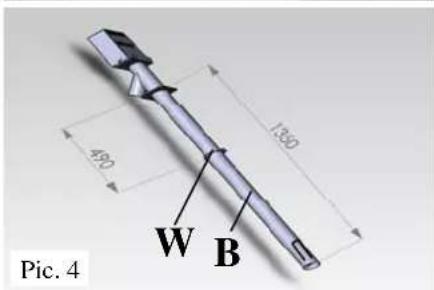
- Insert the ring (W) on the feeder tube (B) and fasten it at the distance indicated in fig. 4
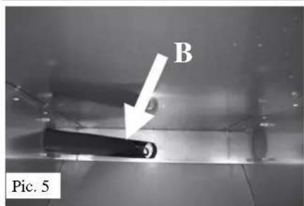
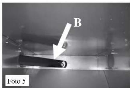
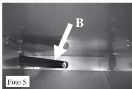
- Insert the feeder tube (B) with the auger, making sure that the feed slot is facing upwards (photos 4 and 5).
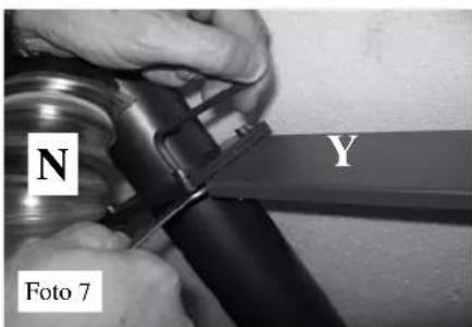
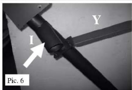
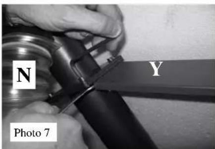
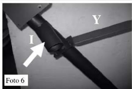
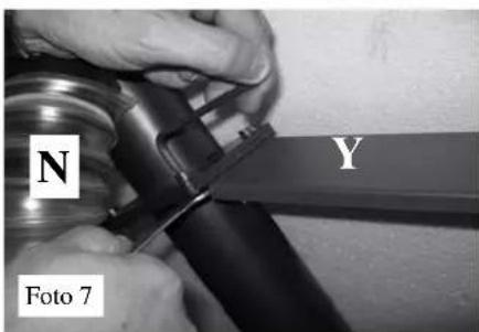
- Install the conveyor (I) facing the rear side of the boiler (Pic. 6) and fasten it to the support (Y) using the screws provided (Pic. 7).
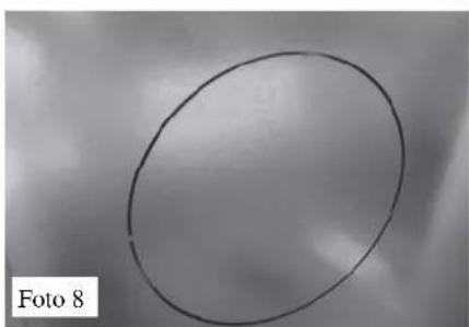
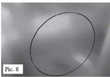
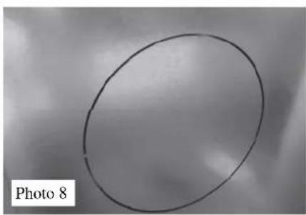
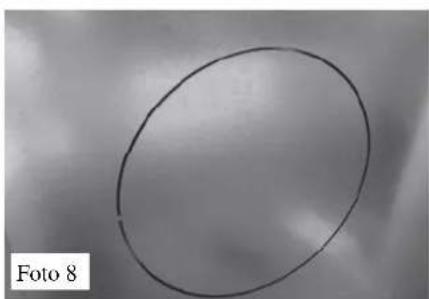
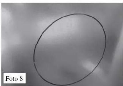
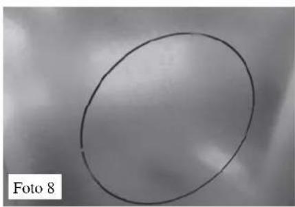
- Remove the pre-cut lidon the back of the boiler (Pic. 8), unscrew the fastening screws of the closing flange located under the pre-cut lid and replace it with a flexible pipe connection flange (M -Pic. 9).
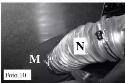
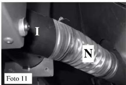
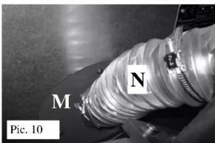
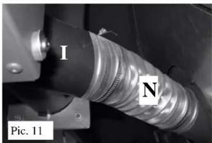
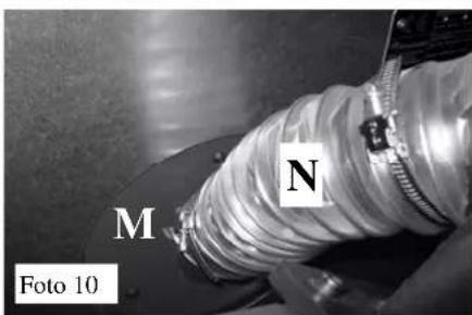
- Connect the flexible tube (N-photos 10 and 11) to the conveyor tube (I - photos 6-11) and to the flexible tube connection flange (M-photos 9 and 10), and secure it using the supplied cable ties.
Note: the flexible pipe (N) must be positioned so that it carries the pellets to the tank without causing bottlenecks (Pic. 11); verify the unit's proper functionality during the initial loading operations, and use silicone to seal any powder leaks that may be encountered.
natural_image
Close-up of a pipe joint with a labeled component 'O' and caption 'Pic. 1' (no other text or symbols)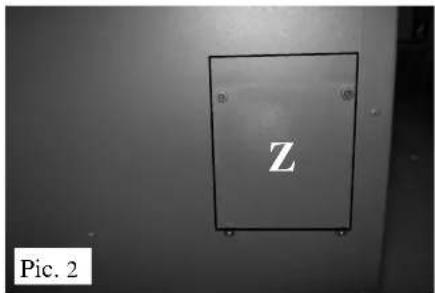

natural_image
Simple hand-drawn oval shape on a textured gray background, labeled 'Pic. 8' in the corner (no other text or symbols)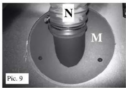
MOUNTING THE COMPONENTS
Fastening the electronic regulator (R) to the tank
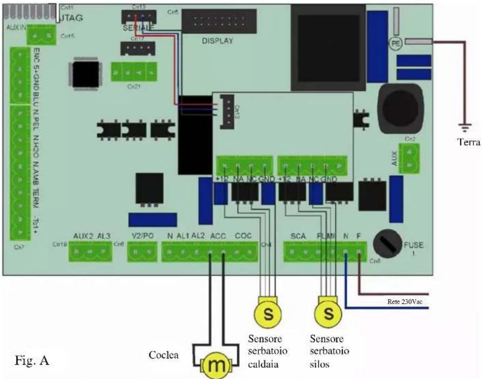
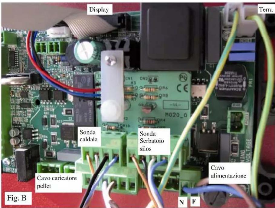
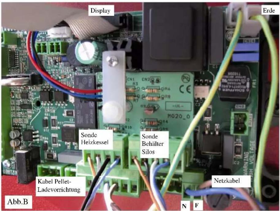
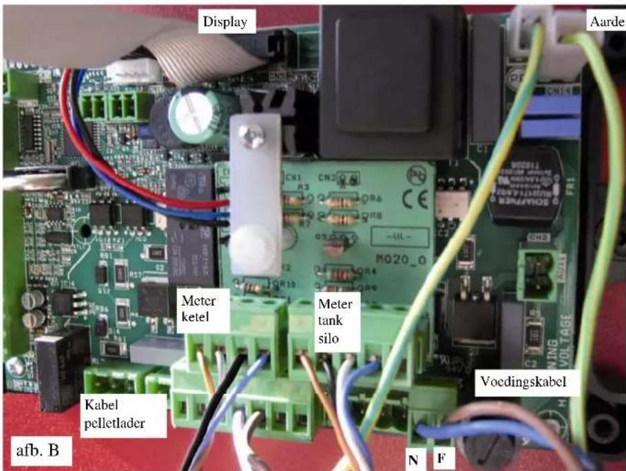
The electronic regulator (R) is delivered already wired in its box which then must be installed in the dedicated housing on the front of the tank and then fix the earthing cable(P) (Pics. 11-12).
If installation is difficult, you can remove the lid by loosening the 4 screws.
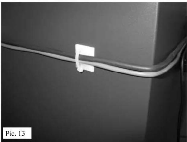
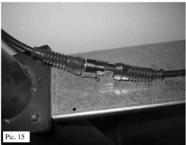
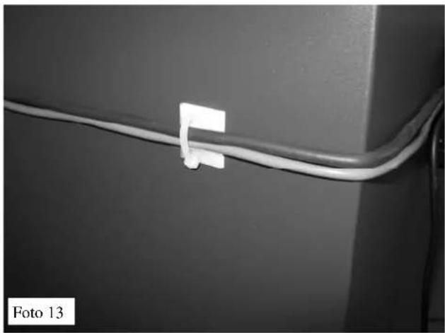
Bring the power cable to the motor and secure it:
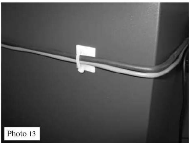
- to the side of the tank with the adhesive plate and clamp (Pic. 13)
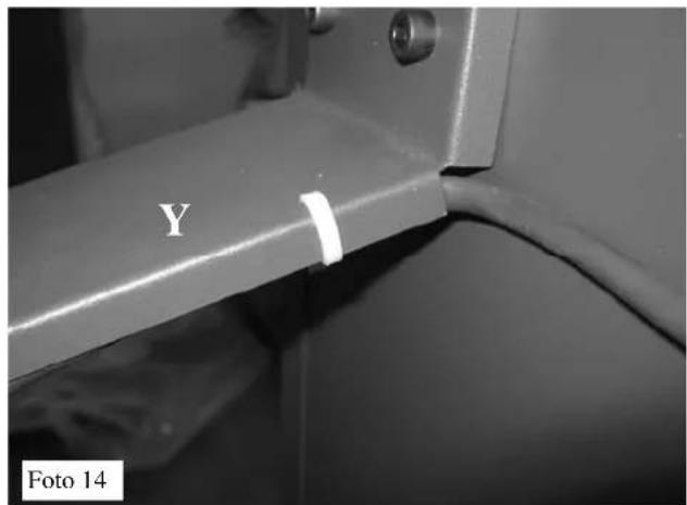
- to the feeder tube support (Y) using the cable ties (photo 14)
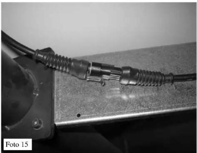
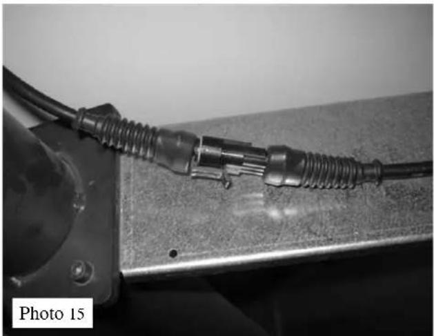
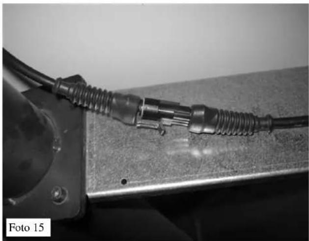
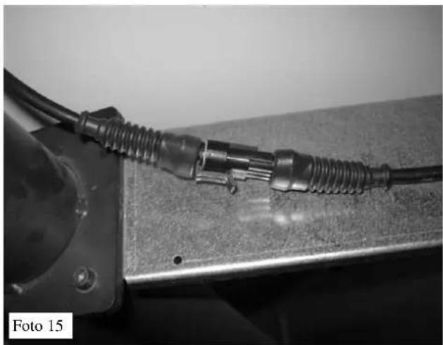
Insert the plug into the motor outlet (pic. 15)
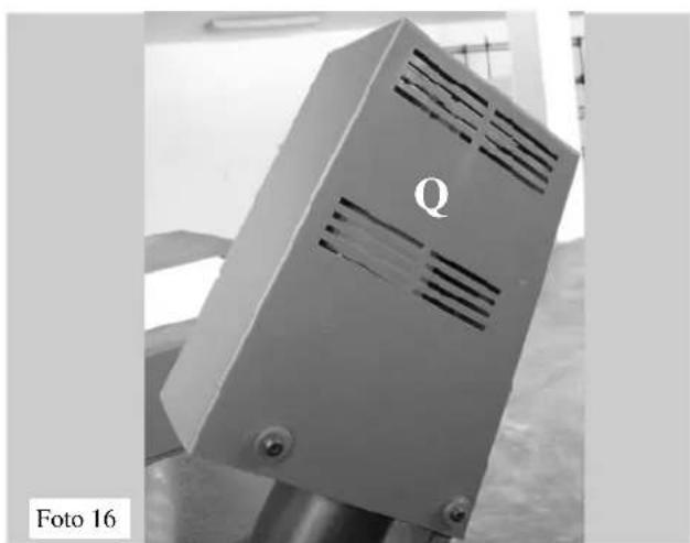
Attention: prevent the casing (Q) - (pic. 16) from coming into contact with the gear motor blades.

natural_image
Metal panel with a small electronic component labeled 'R' and 'Pic. 11' (no readable text or symbols beyond labels)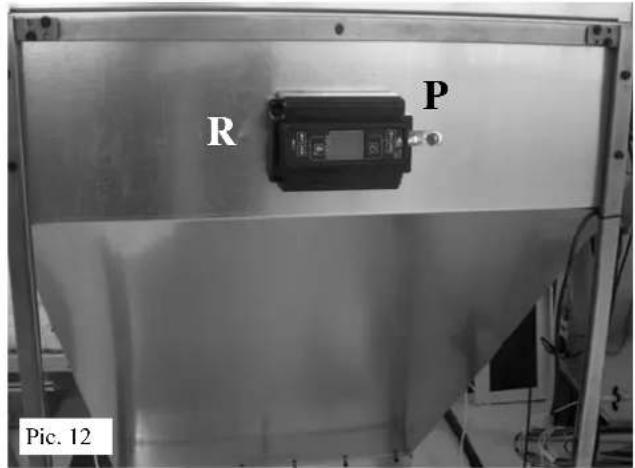
natural_image
Close-up of a white cable with a small square clip attached, mounted on a dark surface (no text or symbols visible)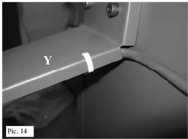
natural_image
Close-up of a metallic mechanical component with threaded connectors and a labeled section (no readable text or symbols)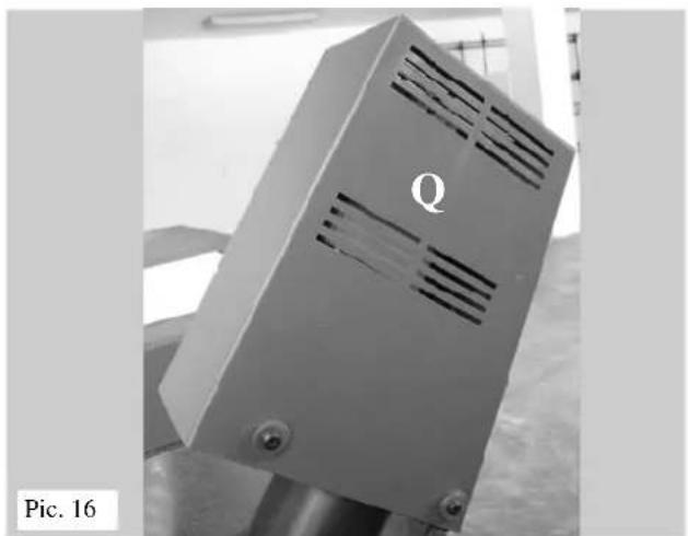
natural_image
Metallic industrial device with ventilation slots and label 'Q', no readable text or symbols beyond the labelELECTRICAL CONNECTIONS
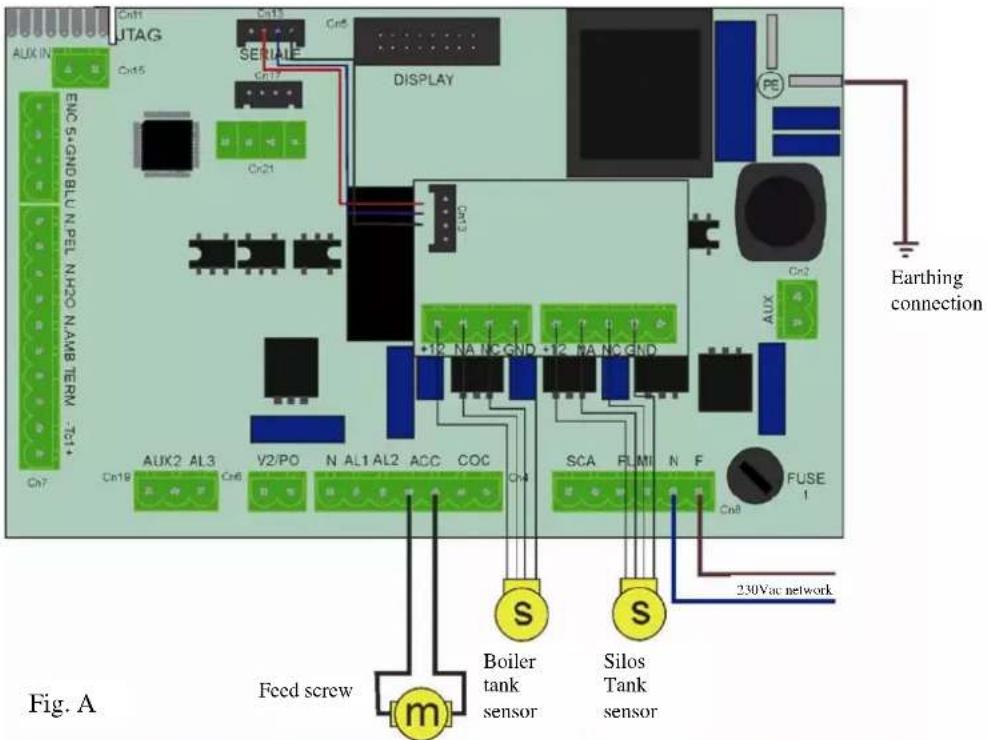
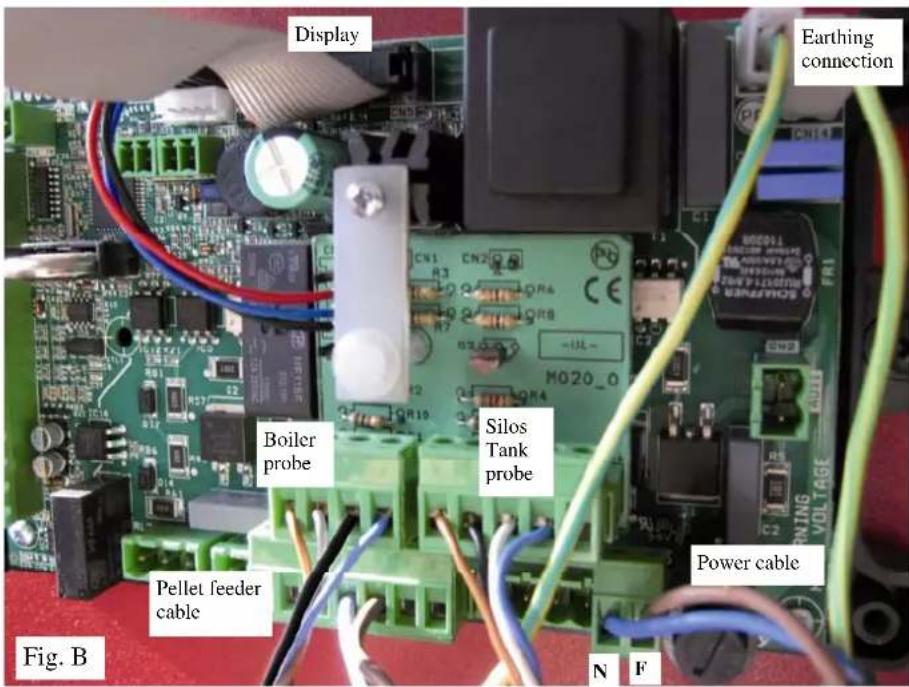
| ELECTRICAL CHARACTERISTICS | |
| Power Supply | 230V +/- 10% 50Hz |
| Gear motor power when empty | 70 W |
| Gear motor power when under load | 120 W |
| Motor thermal protector | 130 °C |
| Circuit board protection | 4A 250 V Fuse |
IMPORTANT:
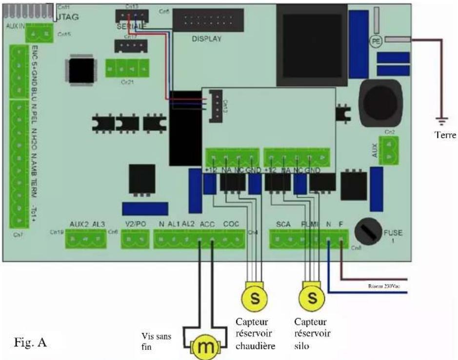
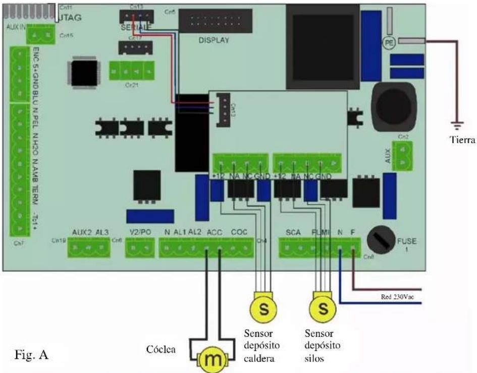
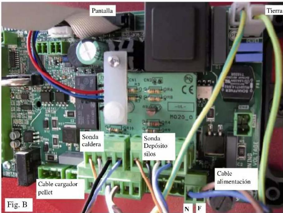
During installation, the tank must be grounded. Connect an earthing cable to the appropriate slot on the side of the tank.
INSTALLATION
FASTENING THE PROBES
Probe for detecting the "Minimum pellet" level IN THE TANK ON THE BOILER.
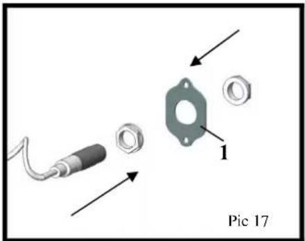
- Secure the probe to the perforated galvanized plate (1 - supplied) using the ferrules on the probe itself (photos 17-17a).
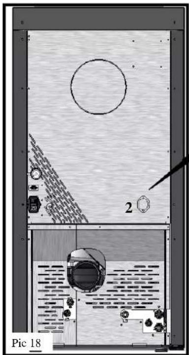
- Remove the blind plate (2 - photos 18-18a) on the rear of the boiler and replace it by screwing the plate (1), complete with the probe, into position 3 (photo 18b).
natural_image
Technical diagram of a mechanical or architectural component with labeled parts and internal features (no readable text or symbols)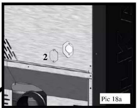
natural_image
Exterior view of a vehicle or industrial facility with two circular components labeled '2' and 'Pic 18a' (no readable text beyond labels)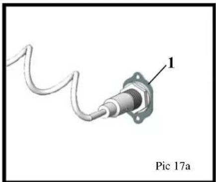
natural_image
Close-up of a mechanical component with a coiled cable and labeled part 1, no readable text or symbols beyond label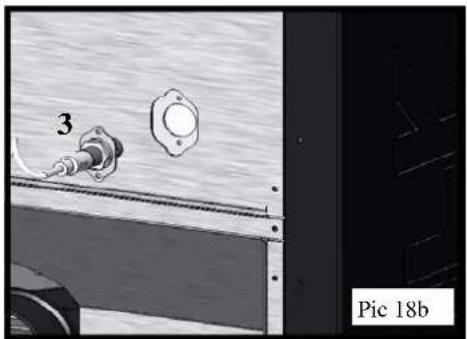
natural_image
Close-up of a mechanical component with a numbered part (3) and a flanged housing, no visible text or symbols.Probe for detecting the "Minimum pellet" level IN THE EXTERNAL TANK.
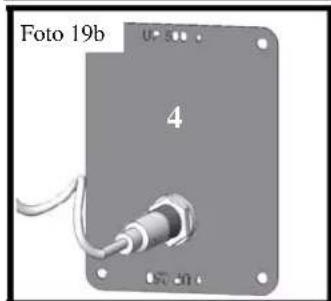
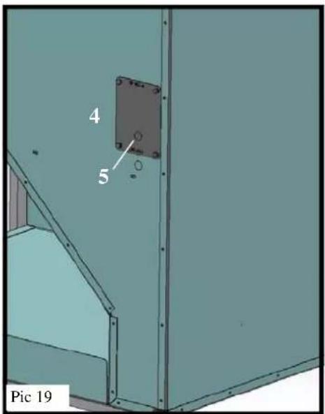
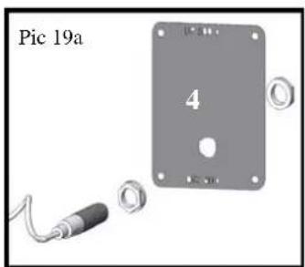
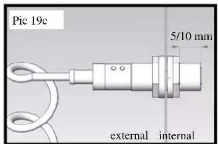
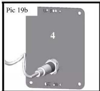
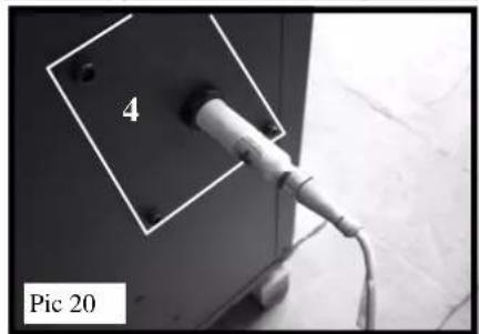
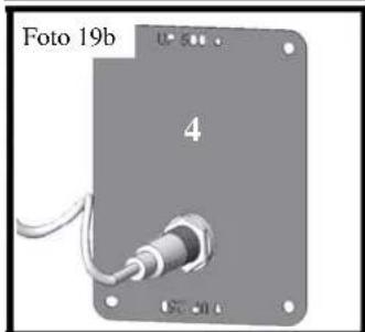
- Remove the closing plate (4 - photo 19) and open the pre-cut hole (5) on the plate itself. - Secure the probe to the plate (4) using the ferrules on the probe itself (photos 19a-19b). - The probe should protrude approximately 5/10 ~mm from the inner ferrule (photo 19c). - Reposition the plate (4 - photo 20) (with the inscription "UP 500" facing upwards), being careful not to damage the electrical cable.
Verify the probes' proper installation by checking that the led indicators corresponding to the appropriate icons light up on the electronic regulator's display (see fig. 22 on page 19).
MAKE SURE THAT THE PROBE DOES NOT COME INTO CONTACT WITH HEAT SOURCES (e.g. SMOKE OUTLET).
natural_image
Close-up of a plug inserted into a wall socket, labeled '4' and 'Pic 20' (no other text or symbols visible)REGULATOR DESCRIPTION
Connect the power cable's schuko plug, that comes out of the electronic regulator, to the network outlet (possibly equipped with a magneto-thermal circuit breaker).
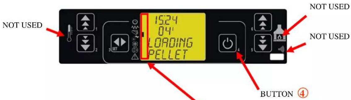
The console unit allows for communication with the electronic regulator by simply pressing some keys.
A display informs the operator of the load system's operating status.
In the programming mode, the various parameters that can be modified using the keys are displayed.
Pic. 21
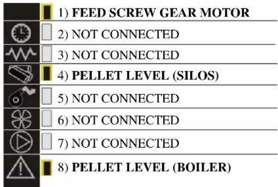
Pic. 22 describes the meaning of the symbols located on the left side of the display.
The activation on the display of one of the led segments, signals the activation of the corresponding device, according to the list at the side.
Pic.22
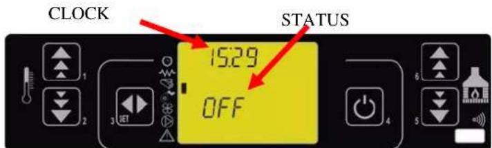
fig. 23
FUNCTION
Pic. 24
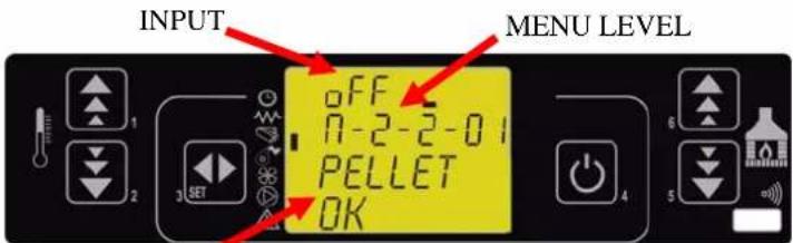
Pic. 24 describes the arrangement of messages during the programming phase or when setting operating parameters. In particular:
- The input area displays the programming values entered.
- The "menu level" area, displays the current menu level. Refer to the Menu chapter.
Before the regulator is switched on the display appears as shown in pic 25.
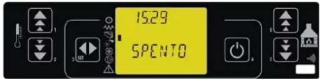
Pic. 25
Switching on the control
To switch on the control, press the P4 button for a few seconds. When the regulator is switched on the display appears as shown in figura 26.
Language selection
To select the language press the SET button (P3) and "CHOOSE LANGUAGE" will appear. Press the SET button (P3) again and "MENU 01 - ITA" will appear.
Using the P1 and P2 buttons select the desired language, confirm the selection by pressing P4 twice.
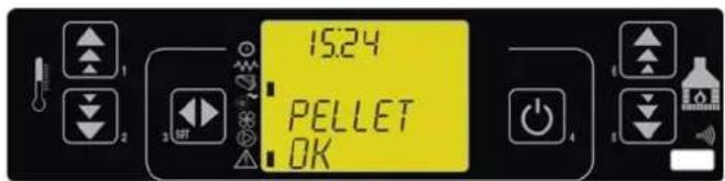
Pic. 26
When the sensor detects an insufficient pellet level, the regulator checks the pellet reserve (pic 27) for 7 seconds; if the level is restored, the pellet present message comes back as in pic 26, otherwise after 7 seconds pellet loading will start. (see pic 28).
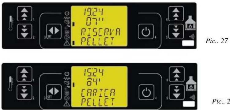
Immediately after this verification, the pellet load phase will be activated for the load time set.
If after the load time expires, the level is restored, the message "PELLETS PRESENT" will appear, disabling loading; otherwise, and alarm will be signalled and the feed screw motor will switch off.
Switch-off.
To switch off the feeder, simply press down the 4 button for approx. 2 seconds.
The feed screw will stop immediately and the display will appear as in pic 29.
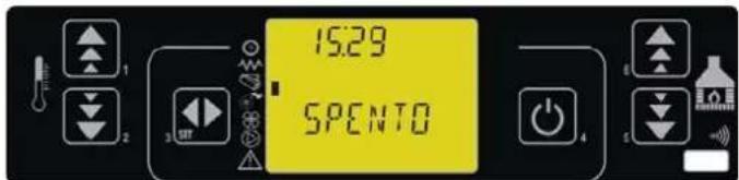
Pic. 29
ALARMS
Additional tank empty alarm.
This alarm is displayed when the additional tank is empty (pic 30).
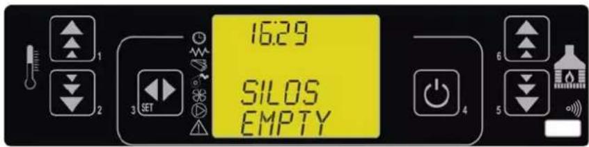
Pic. 30
To restore the tank to working order, load the pellets and press button 4.
Pellet supply exhausted alarm.
The alarm is displayed when the programmed pellet load time expires if the pellet level in the boiler's tank is still below the probe's min. level.
In this case the message "PELLETS EXHAUSTED" will appear on the display and then after 10 seconds the message "OFF" will appear.
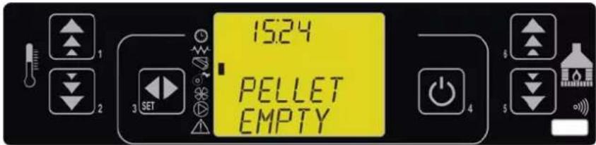
Pic. 31
ContrCheck the cause of the pellet supply's exhaustion (motor block, motor failure, conveyor tube clog, insufficient load time).
To restore the tank to working order, restore the pellet level in the tank and press the 4 button.
DECLARATION OF CONFORMITY
The product conforms to the essential requirements of the following EEC Directives:
- 2006/42/EC
- 2006/95/EC
- 2004/108/EC
Therefore, it is has the CE marking

EDILKAMIN S.p.a.
registered office in Via Vincenzo Monti 47
20123 Milan
Madame, Monsieur,
natural_image
Technical line drawing of a mechanical assembly or enclosure with no visible text or symbols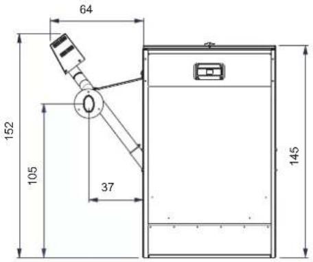
natural_image
Simple line drawing of a rectangular frame with a vertical rod and angle marker (no text or symbols)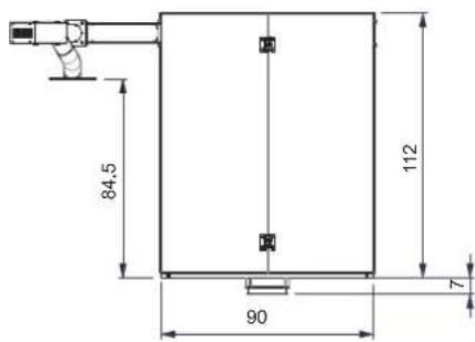
B = tuyau chargeur (options)
I = tuyau convoyeur (options)
M = bride prise de tuyau flexible (options)
N = tuyau flexible (options)
natural_image
Two simple 3D L-shaped metal profiles labeled A, no text or symbols presentPHASE 1 :
PHASE 2 :
ASSEMBLAGE DU CHASSIS
PHASE 5 :
natural_image
3D diagram of a stepped metal profile with labeled points D and E (no text or symbols beyond labels)PHASE 3 :
natural_image
3D diagram of a mechanical part with labeled section 'G' (no other text or symbols)PHASE 6 :
natural_image
3D diagram of a mechanical housing or enclosure with labeled components H, showing internal structural elements (no text or symbols beyond labels)PHASE 7 :
natural_image
3D diagram of a mechanical device with labeled components (T), showing internal structure and handle mechanism (no text or symbols beyond labels)PHASE 11 :
natural_image
3D diagram of a rectangular box with a cutout showing internal structure and label 'L' (no text or symbols beyond the label)MONTAGES DES COMPOSANTS OPTIONS
LISTE DES COMPOSANTS :
N = tuyau flexible
Z = plaque de fermeture
B = tuyau chargeur
natural_image
Close-up of a black metal door with a white letter 'Y' on the side, no visible text or symbols beyond the letter.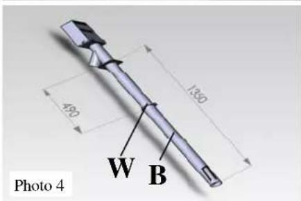
natural_image
Simple hand-drawn oval shape on a textured gray background, labeled 'Photo 8' in the corner (no other text or symbols)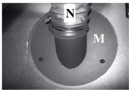
natural_image
Close-up of a mechanical component with labeled parts N and M, showing a central shaft and flange (no text beyond labels)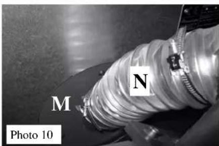
natural_image
Close-up of a mechanical component with labeled parts M and N, no readable text or symbols beyond labels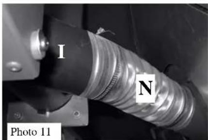
natural_image
Close-up of a mechanical component with labeled parts I and N, no readable text or symbols beyond labelsPhoto 9
MONTAGES DES COMPOSANTS
natural_image
Metallic device with a small circuit board labeled 'R' and 'Photo 11' at the bottom (no readable text or symbols on the device itself)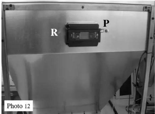
natural_image
Close-up of a white cable with a small square clip attached, mounted on a dark surface (no text or symbols visible)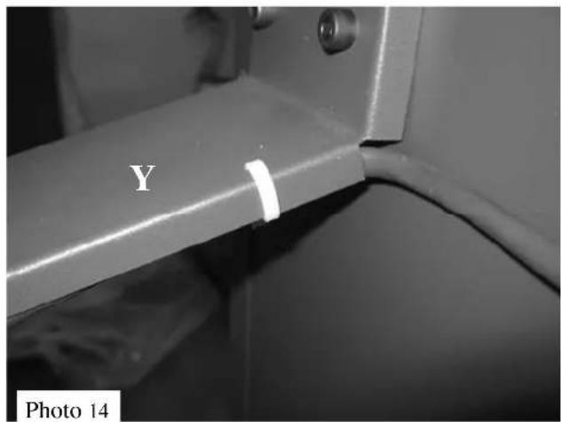
natural_image
Close-up of a metallic mechanical component with threaded connectors and a labeled photo (no text or symbols on the main subject)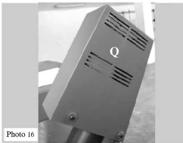
natural_image
Close-up of a metallic industrial device with ventilation slots and a labeled part 'Q', shown in black and white (no readable text or symbols beyond label)BRANCHEMENTS ÉLECTRIQUES
natural_image
Interior view of a room with a circular object on the wall and a window with a camera lens, showing no visible text or symbols.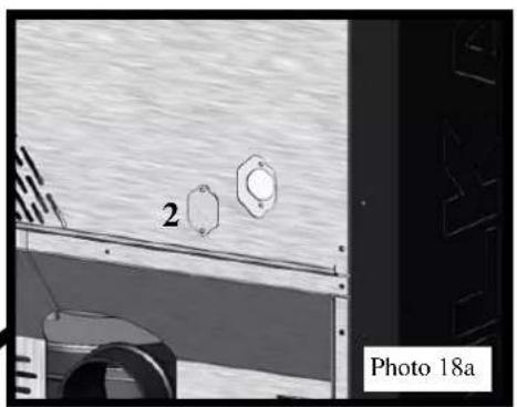
natural_image
Exterior view of a vehicle or industrial facility with two circular components labeled '2' and 'Photo 18a' (no readable text beyond labels)
natural_image
Close-up of a metallic connector with coiled cable and mounting base, labeled with number 1 (no text or symbols on the component itself)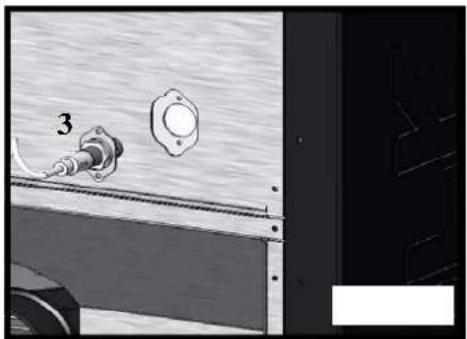
natural_image
Close-up of a mechanical component with a numbered part (3) and a mounting flange, no visible text or symbols.natural_image
Electronic device panel with labeled pins and wiring, no readable text or symbols beyond labels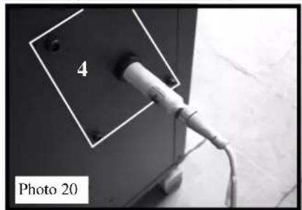
natural_image
Close-up of a white cable plugged into a black panel with a numbered label '4' and 'Photo 20' (no other text or symbols visible)DESCRIPTION RÉGULATEUR
Fig. 25
Pic. 29
ALARMES
DÉCLARATION DE CONFORMITÉ
- 2006/42/EC
- 2006/95/EC
- 2004/108/EC
natural_image
Two simple 3D L-shaped metal profiles labeled A, no text or symbols presentFASE 1:
FASE 2: EMSAMBLAJE DEL BASTIDOR
FASE 5:
natural_image
3D diagram of a stepped metal profile with labeled points D and E (no text or symbols beyond labels)FASE 3:
natural_image
3D diagram of a mechanical part with labeled section 'G' (no other text or symbols)FASE 6:
natural_image
3D diagram of a mechanical housing or enclosure with labeled components H, showing internal structure and mounting holes (no text or symbols beyond labels)FASE 7:
natural_image
3D diagram of a mechanical device with labeled components (T), showing internal structure and handle mechanism (no text or symbols beyond labels)FASE 11:
FASE 12:
natural_image
3D diagram of a transparent industrial machine with labeled components (t, j, J) and internal structure (no text or symbols beyond labels)FASE 13:
natural_image
3D diagram of a geometric box with a cutout and labeled corner 'L' (no text or symbols beyond the label)FASE 10:
natural_image
Close-up of a black electronic device with a metallic Y-shaped label and mounting bracket (no readable text or symbols)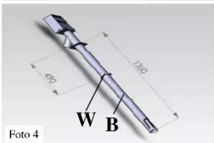
natural_image
Simple hand-drawn oval shape on a textured gray background, labeled 'Foto 8' in the corner (no other text or symbols)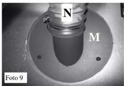
natural_image
Close-up of a white cable with a small square clip attached, mounted on a dark surface (no text or symbols visible)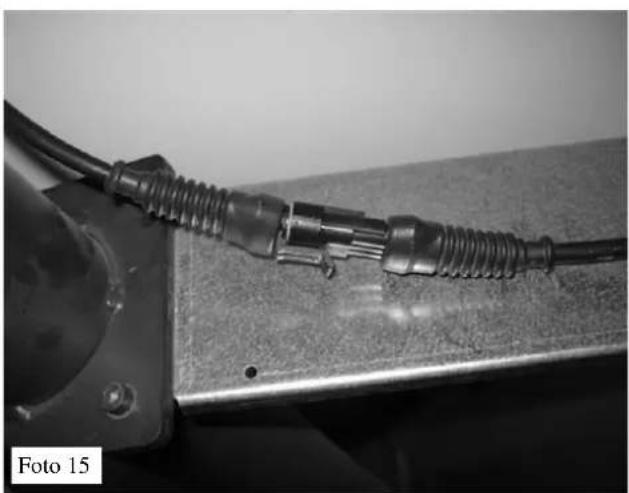
natural_image
Close-up of a metallic mechanical component with threaded connectors and a circular base, labeled 'Foto 15' in the corner (no other text or symbols visible)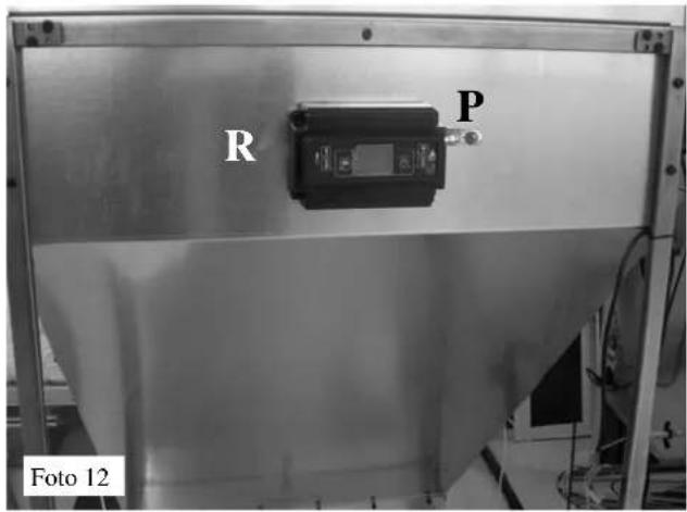
natural_image
Metallic industrial component with ventilation slots and label 'Q', no readable text or symbols beyond the labelCONEXIONES ELÉCTRICAS
natural_image
Exploded view diagram of a mechanical component with labeled parts (no text or symbols beyond labels)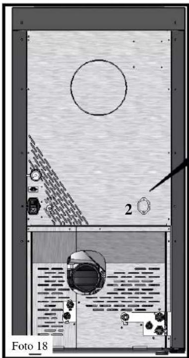
natural_image
Interior layout diagram of a ship's deck with numbered components and a circular feature, no readable text or symbols.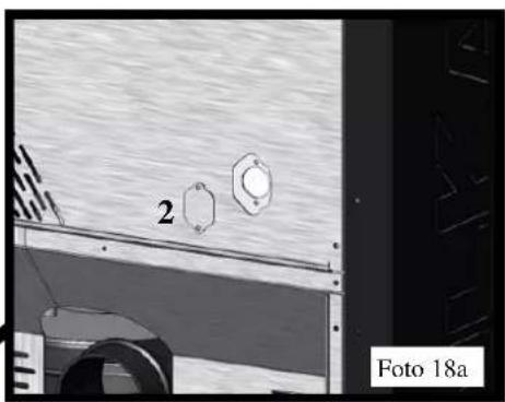
natural_image
Exterior view of a vehicle with two circular components and a numbered label '2' (no readable text or symbols beyond labels)
natural_image
Close-up of a mechanical component with a coiled cable and labeled part 1, no readable text or symbols beyond label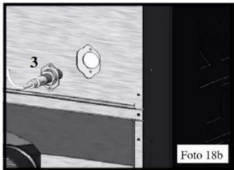
natural_image
Close-up of a mechanical component with a numbered part (3) and a circular feature, no visible text or symbols.natural_image
Electronic component with labeled part '4' and wiring, no readable text or symbols beyond labels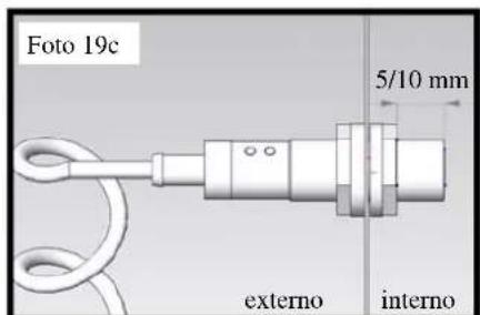
natural_image
Electronic component with labeled pins and wiring, no readable text or symbols beyond labels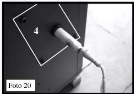
natural_image
Close-up of a cable plugged into a wall socket, labeled '4' and 'Foto 20' (no other text or symbols visible)Pic. 29
ALARMAS
- 2006/42/EC
- 2006/95/EC
- 2004/108/EC

natural_image
Two simple L-shaped metal lines labeled A, no text or symbols presentSCHRITT 1:
SCHRITT 2:
MONTAGE DES RAH- MENS
SCHRITT 5:
natural_image
3D diagram of a stepped metal profile with labeled points D and E (no text or symbols beyond labels)SCHRITT 3:
natural_image
3D diagram of a mechanical part with a labeled section 'G' (no other text or symbols)SCHRITT 6:
natural_image
3D diagram of a mechanical housing or enclosure with labeled components H, showing internal structural lines (no text or symbols beyond labels)SCHRITT 7:
natural_image
3D diagram of a mechanical device with labeled components (T), showing internal structure and handle mechanism (no text or symbols beyond labels)SCHRITT 11:
SCHRITT 12:
natural_image
3D diagram of a mechanical device with labeled components (t, j, J) and internal structure (no text or symbols beyond labels)SCHRITT 13:
natural_image
3D diagram of a cube with an L-shaped cutout, no text or symbols presentMONTAGE DER KOMPONENTEN ZUBEHÖR
KOMPONENTENLISTE:
N = Schlauch
natural_image
Close-up of a pipe joint with a rectangular inset labeled 'O' and 'Foto 1' (no other text or symbols visible)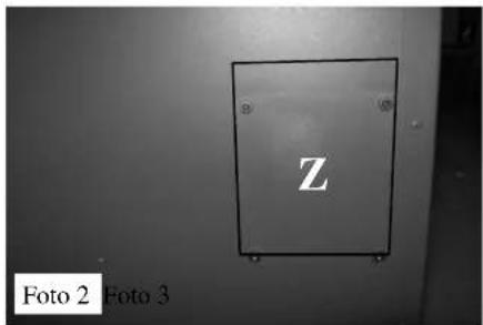
natural_image
Close-up of a black metal cabinet with a white letter 'Y' on its side, no visible text or symbols beyond the letter.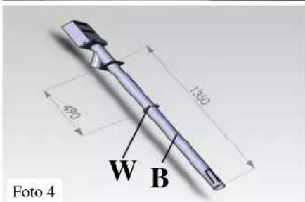
natural_image
Simple hand-drawn oval shape on a textured surface, labeled 'Foto 8' in the corner (no other text or symbols)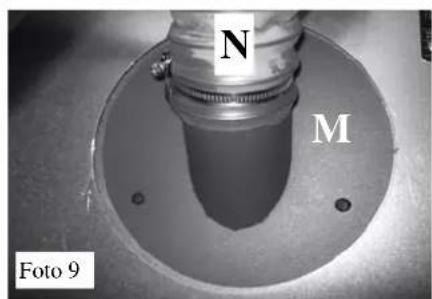
natural_image
Close-up of a mechanical component with labeled parts M and N, no readable text or symbols beyond labels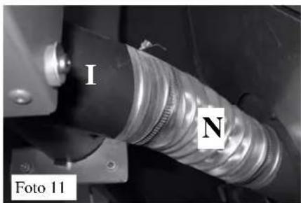
MONTAGE DER KOMPONENTEN
natural_image
Close-up of a white cable with a small square clip attached, mounted on a dark surface (no text or symbols visible)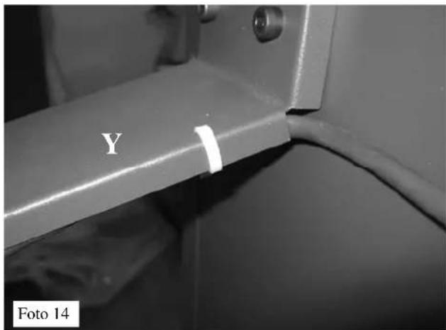
natural_image
Close-up of a metallic mechanical component with threaded connectors and a circular base, labeled 'Foto 15' in the corner (no other text or symbols visible)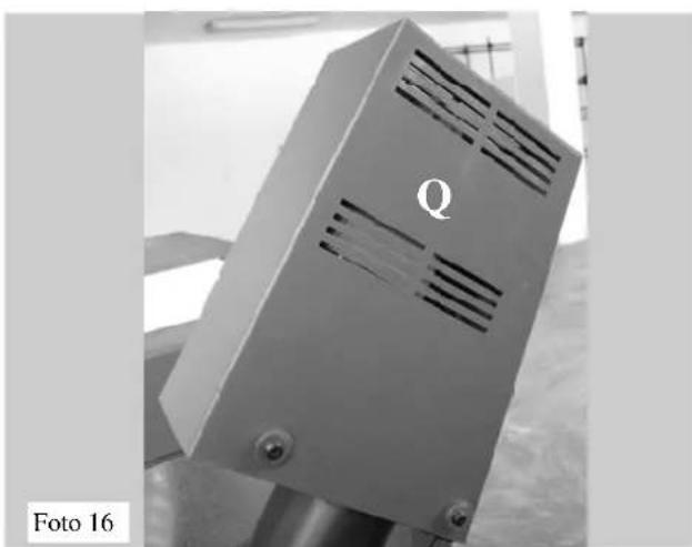
natural_image
Metal enclosure with ventilation grilles and mounting base, labeled 'Q' (no text or symbols on the object itself)ELEKTROANSCHLÜSSE
natural_image
Exploded view diagram of a mechanical component with labeled parts (no text or symbols beyond labels)
natural_image
Interior layout diagram of a room with circular elements and labeled components, no readable text or symbols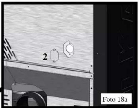
natural_image
Exterior view of a vehicle or industrial facility with two circular components and a numbered label '2' (no readable text or symbols beyond labels)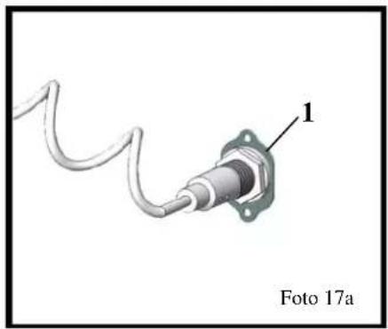
natural_image
Close-up of a mechanical component with a coiled cable and labeled part 1, no readable text or symbols beyond label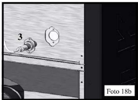
natural_image
Close-up of a mechanical component with a numbered part (3) and a circular housing, next to a door frame (no visible text or symbols)natural_image
Close-up of a cable plugged into a wall socket, labeled '4' and 'Foto 20' (no other text or symbols visible)Abb. 25
Abb. 29
ALARM
- 2006/42/EC
- 2006/95/EC
- 2004/108/EC
natural_image
Two simple L-shaped metal lines labeled A, no text or symbols presentFASE 1:
FASE 2:
HET FRAME MONTEREN
FASE 5:
natural_image
3D diagram of a stepped metal profile with labeled points D and E (no text or symbols beyond labels)FASE 3:
natural_image
3D diagram of a mechanical part with a labeled section 'G' (no other text or symbols)FASE 6:
natural_image
3D diagram of a mechanical housing or enclosure with labeled components H, showing internal and external planes (no text or symbols beyond labels)FASE 7:
natural_image
3D diagram of a mechanical device with labeled components (T), showing internal structure and handle mechanism (no text or symbols beyond labels)FASE 11:
FASE 12:
natural_image
3D diagram of a transparent enclosure with labeled components (t, j, j) and internal structure (no text or symbols beyond labels)FASE 13:
natural_image
3D diagram of a rectangular box with a cutout and labeled corner 'L' (no text or symbols beyond the label)COMPONENTEN MONTEREN OPTIES
LIJST MET ONDERDELEN:
N = flexible leiding
Z = sluitplaat
B = toevoerleiding
natural_image
Close-up of a pipe with a rectangular component labeled 'O' and 'Foto 1' (no other text or symbols visible)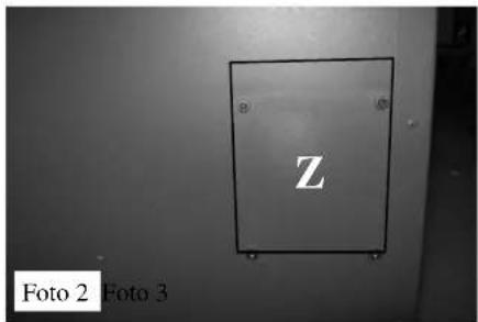
natural_image
Close-up of a black metal door with a white letter 'Y' on the side, mounted on a wall (no visible text or symbols beyond the letter)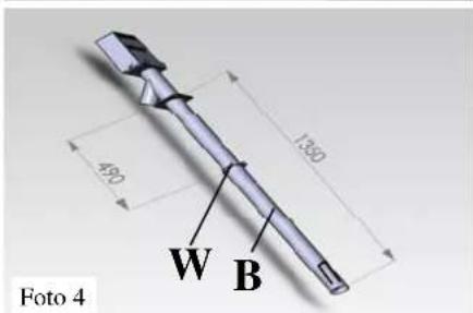
natural_image
Simple hand-drawn oval shape on a textured surface, labeled 'Foto 8' in the corner (no other text or symbols)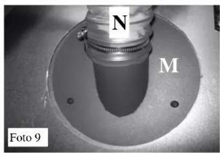
COMPONENTEN MONTEREN
Bevestig de elektronische regelaar (R) op de tank
natural_image
Metal panel with a small electronic component labeled 'R' and 'Foto 11' (no readable text or symbols beyond labels)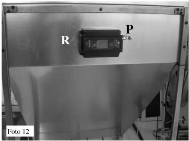
natural_image
Close-up of a white cable with a small square clip attached, mounted on a dark surface (no text or symbols visible)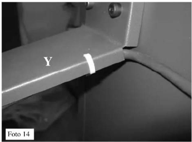
natural_image
Close-up of a metallic mechanical component with threaded connectors and a metal frame, labeled 'Foto 15' in the corner (no other text or symbols visible)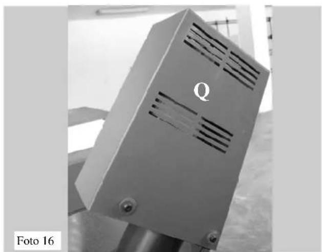
natural_image
Exterior view of a metallic industrial device labeled 'Q' with cutouts, mounted on a stand (no readable text or symbols beyond label)
natural_image
Interior view of a room with a circular object, floor plan, and equipment (no readable text or symbols)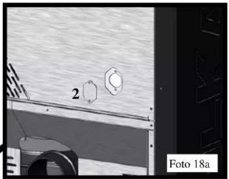
natural_image
Exterior view of a vehicle or industrial facility with two circular components and a numbered label '2' (no readable text or symbols beyond labels)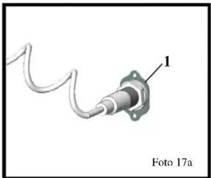
natural_image
Close-up of a mechanical component with a coiled cable and labeled part 1, no readable text or symbols beyond label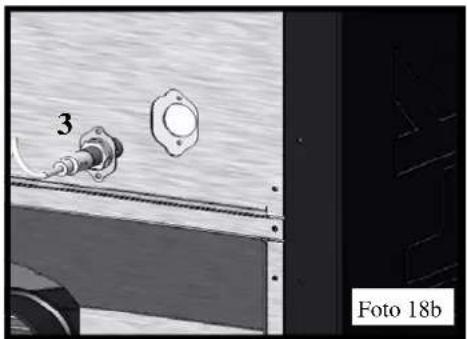
natural_image
Technical diagram showing a mechanical assembly with a numbered component and a labeled section (Foto 18b), no readable text or symbols present.natural_image
Close-up of a plug inserted into a wall socket, with no visible text or symbols on the socket itself.Afb. 25
De controle inschakelen
Afb. 29
ALLARMEN
Alarm extra tank leeg.
- 2006/42/EC
- 2006/95/EC
- 2004/108/EC

- FASE 1:
- FASE 2:
- ASSEMBLAGGIO DEL TELAIO
- FASE 5:
- FASE 3:
- FASE 6:
- MONTAGGIO COMPONENTI
- COLLEGAMENTI ELETTRICI
- ALLARMI
- METALLIC BODY ASSEMBLY
- LIST OF COMPONENTS:
- PHASE 1:
- PHASE 4:
- PHASE 2:
- ASSEMBLING THE FRAME
- PHASE 5:
- PHASE 3:
- PHASE 6:
- MOUNTING THE COMPONENTS OPTIONAL
- MOUNTING THE COMPONENTS
- Fastening the electronic regulator (R) to the tank
- ELECTRICAL CONNECTIONS
- IMPORTANT:
- INSTALLATION
- FASTENING THE PROBES
- REGULATOR DESCRIPTION
- Switching on the control
- Language selection
- Switch-off.
- ALARMS
- Pellet supply exhausted alarm.
- DECLARATION OF CONFORMITY
- PHASE 1 :
- PHASE 2 :
- ASSEMBLAGE DU CHASSIS
- PHASE 5 :
- PHASE 3 :
- PHASE 6 :
- MONTAGES DES COMPOSANTS OPTIONS
- MONTAGES DES COMPOSANTS
- BRANCHEMENTS ÉLECTRIQUES
- DESCRIPTION RÉGULATEUR
- ALARMES
- DÉCLARATION DE CONFORMITÉ
- FASE 2: EMSAMBLAJE DEL BASTIDOR
- CONEXIONES ELÉCTRICAS
- ALARMAS
- SCHRITT 1:
- SCHRITT 2:
- MONTAGE DES RAH- MENS
- SCHRITT 5:
- SCHRITT 3:
- SCHRITT 6:
- MONTAGE DER KOMPONENTEN ZUBEHÖR
- MONTAGE DER KOMPONENTEN
- ELEKTROANSCHLÜSSE
- ALARM
- HET FRAME MONTEREN
- COMPONENTEN MONTEREN OPTIES
- COMPONENTEN MONTEREN
- Bevestig de elektronische regelaar (R) op de tank
- De controle inschakelen
- ALLARMEN
Brand : EDILKAMIN
Model : SERBATOIO 500 Kg
Category : Boiler