
ProjectPro 213 Extra - Paint spray WAGNER - Free user manual and instructions
Find the device manual for free ProjectPro 213 Extra WAGNER in PDF.


| Brand | Wagner |
| Model | ProjectPro 213 Extra |
| Product Type | Low-pressure electric spray gun |
| Color | Blue/red (depending on front panel) |
| Weight | 13.6 kg |
| Power supply | 230-240 V ~, 50/60 Hz |
| Power consumption | 570 W |
| Spray power | 130 W |
| Double electrical insulation | Yes (symbol □) |
| Sound pressure level | 80 dB(A) |
| Vibration level | < 2.5 m/s² |
| Maximum product flow rate | 240 g/min |
| Maximum viscosity | 170 DIN-s |
| Air hose length | 7.5 m |
| Adjustable spray pattern type | Flat vertical, flat horizontal, round |
| Cup capacity | 800 ml (aluminum) |
| Applicable products | Solvent-based/water-based paints, lacquers, glazes, varnishes, primers, oils, wood/metal protection |
| Non-applicable products | Acidic products, flash point < 21°C |
| Thermal protection | Yes (shutdown in case of overheating) |
| Maintenance and cleaning | Clean after each use; do not immerse handle; use solvent/water; replace air filter regularly |
| Safety | Use protective equipment (goggles, mask, gloves); do not spray flammable products; keep out of reach of children; unplug before maintenance |
| Spare parts available | Yes (nozzles, caps, seals, membranes, filters, reservoirs, removable front panels) |
| Warranty | 24 months private use, 12 months commercial use |
| Repairability | Repair by qualified personnel; original spare parts recommended |
| General information | French manual available; Wagner France customer service |
Frequently Asked Questions - ProjectPro 213 Extra WAGNER
User questions about ProjectPro 213 Extra WAGNER
0 question about this device. Answer the ones you know or ask your own.
Ask a new question about this device
Download the instructions for your Paint spray in PDF format for free! Find your manual ProjectPro 213 Extra - WAGNER and take your electronic device back in hand. On this page are published all the documents necessary for the use of your device. ProjectPro 213 Extra by WAGNER.
USER MANUAL ProjectPro 213 Extra WAGNER
natural_image
Exterior view of a twin turbo air purifier with visible branding and control panel (no text-heavy elements)

ProjectPro
213 Extra
D/GB/F/NL

ProjectPro 213 Extra
natural_image
Technical line drawing of a mechanical component with no visible text or symbols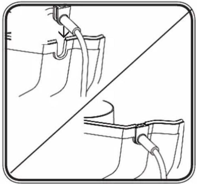
natural_image
Diagram showing two mechanical setups with pipes and a valve, no text or symbols present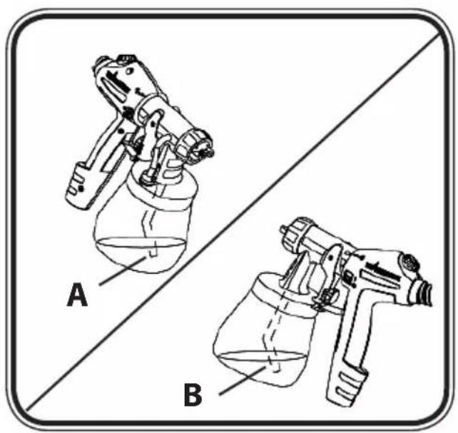
natural_image
Two spray gun holders labeled A and B, shown against a diagonal line (no text or symbols on the devices themselves)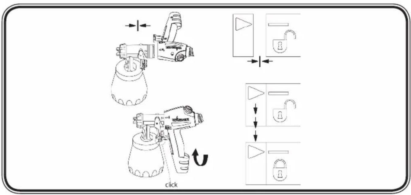
5
11A
11B
natural_image
Mechanical assembly diagram showing gear and shaft components with directional arrows (no text or labels)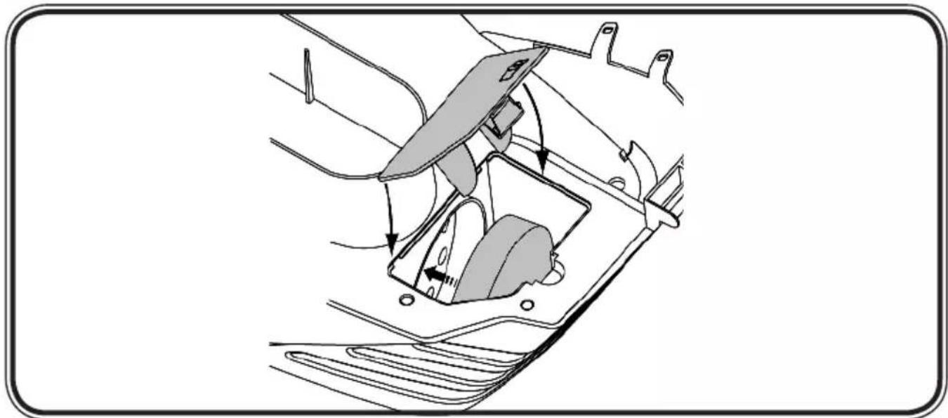
natural_image
Diagram of a car's seatbelt mechanism showing hand placement and wheel movement (no text or labels)1 - 12
GB 13-24
F 25 - 36
NL 37 - 48

flowchart
graph LR
    A["Telephone"] + B["Envelope"] + C["Printer"] --> D["Global Map"]
    D --> E["50"]
    style A fill:#f9f,stroke:#333
    style B fill:#f9f,stroke:#333
    style C fill:#f9f,stroke:#333
    style D fill:#ccf,stroke:#333
    style E fill:#ccf,stroke:#333
Bedienungsanleitung
Operating instruction
Congratulations on purchasing your WAGNER spray guns.
You have purchased a proprietary device that requires careful cleaning and care to ensure trouble-free functioning. Read the operating instructions carefully before using the tool and observe the safety instructions. Keep the operating instructions in a safe place.
General Safety Instructions
Caution!

Read all the instructions. Non-observance of the instructions below can cause electric shock, fire and or serious personal injuries. The term "power tool" used below covers both mains-operated power tools (with mains lead) and accumulator-operated power tools (without mains lead).
1. Workplace
Keep your workplace clean and tidy. a) Untidiness and unlit working areas can lead to accidents.
Never use the tool in hazardous areas that contain flammable liquids, gases b) or dusts. Power tools generate sparks that can ignite the dust or vapors.
Keep children and other persons away when using the power tool. c) You can lose control of the tool if you are distracted.
2. Electrical Safety
The tool plug must fit into the socket. The plug may not be modified in any a) form. Do not use adaptor plugs together with protective-earthed tools.
Unmodified plugs and suitable sockets reduce the risk of an electric shock.
Avoid physical contact with earthed surfaces such as pipes, heating b) elements, stoves and refrigerators. The risk through electric shock increases if your body is earthed.
Keep the equipment away from rain and moisture. c) The risk of an electric shock increases if water penetrates electrical equipment.
d) Do not misuse the mains lead by carrying the tool by the lead, hanging it from the lead or by pulling on the lead to remove the plug. Keep the lead away from heat, oil, sharp edges or moving tool parts. Damaged or twisted leads increase the risk of an electric shock.
e) If you work outdoors, use only extension leads that are approved for outdoor use. The use of an extension lead that is suitable for outdoors reduces the risk of an electric shock.
3. Safety of Persons
Be attentive. Pay attention to what you are doing and work sensibly with a) apower tool. Do not use the tool if you are tired or under the influence of drugs, alcohol or medication. Just a moment of inattentiveness while using the tool can lead to serious injuries.
Wear personal safety equipment and always wear safety goggles b) Wearing personal protective equipment, such as dust mask, non-slip safety shoes, safety helm or ear protection, depending on the type of power tools, reduces the risk of injury.
Avoid accidental starting-up. Ensure that the switch is in the "OFF" position c) before inserting the plug into the socket. Accidents can occur if you carry the power tool while your finger is on the switch or if you connect the power tool to the power supply which it is on.
Remove setting tools or wrenches before switching on the power tool. d) A tool or wrench that is in a rotating tool part can lead to injuries.
Do not overestimate your abilities. Ensure that you are standing securely e) and have your balance at all times. This ensures that you can control the tool better in unexpected situations.
Wear suitable clothing. Do not wear wide clothing or jewelry. Keep yourhair, f) clothes and gloves away from moving parts. Loose clothing, jewelry or long hair can be caught in moving parts.
This appliance is not intended for use by persons (including children) with g) reduced physical, sensory or mental capabilities, or lack of experience and knowledge, unless they have been given supervision or instruction concerning use of the appliance by a person responsible for their safety.
Children should be supervised to ensure that they do not play with the appliance.
4. Careful Handling and Use of Power Tools
Do not overload the tool. Use the power tool designed for the work that you are doing. You work better and safer in the specified performance range if you use the suitable power tool.
b) Do not use power tools whose switch is defective. A power tool that cannot be switched on or off is dangerous and has to be repaired.
c) Remove the plug from the socket before carrying out tool settings, changing accessories or putting the tool away. This precautionary measure prevents unintentional starting of the tool.
d) Store unused power tools so that they are inaccessible to children. Donot let persons use the tool who are not familiar with it or who have not read these instructions. Power tools are dangerous when they are used by inexperienced persons.
e) Take proper care of your tools. Check whether the moving parts functiontrouble-free and do not jam, whether parts are broken or damaged so that the tool function is impaired. Have damaged parts repaired before
using the tool. Many accidents have their origin in power tools that have been maintained badly.
Use the power tool, accessories, insert tools, etc. in accordance with these f) instructions and in a fashion specified for this special tool type. Take the working conditions and the activity to be carried out into consideration. The use of power tools for purposes other than the intended ones can lead to dangerous situations.
5. Service
Have your tool repaired only by qualified specialist personnel and only with a) original spare parts. This ensures that the tool safety is maintained.
If the supply cord is damaged, it must be replaced by the manufacturer or it's b) service agent or a similarly qualified person in order to avoid a safety hazard.
Safety Instructions for Spray Guns
ATTENTION! EXPLOSION HAZARD!

Do not store materials with a flash point below 21^ C in the basic device! Only store materials in the basic device in containers that close airtight! Remove any material that may have leaked into the basic device immediately and allow the device to dry completely before using it! Do not store materials contained solvents in the basic device during operation!
CAUTION! Wear breathing equipment: Paint mist and solvent vapors are damaging to health. Always wear breathing equipment and only work in well ventilated rooms or using supplementary ventilating equipment. It is advisable to wear working clothing, safety glasses, ear protection and gloves.

CAUTION: Danger of injury! Never point the spray stream towards human beings or animals.
The spray gun is to be used only for paints and solvents with a 21°C (32° in UK) flashpoint or higher (See information on the material tin. Hazard class A II and A III permitted).
Do not use the spray guns to spray flammable substances.
The spray guns are not to be cleaned with flammable solvents which have a flashpoint under 21^ C.
Caution against dangers that can arise from the sprayed substance and observe the text and information on the containers or the specifications given by the substance manufacturer.
Do not spray any liquid of unknown hazard potential.
The device may not be used in workplaces covered by the explosion-protection regulations.
To avoid the hazard of explosion when spraying, provide for effective natural or artificial ventilation.
There must be no sources of ignition such as, for example, open fires, smoke of lit cigarettes, cigars and tobacco pipes, sparks, glowing wires, hot surfaces, etc. in the vicinity during spraying.
Ensure that no solvent vapors are sucked in by the unit. Do not spray onto the unit!
The spray gun is not a toy; children must therefore not be allowed to handle it or play with it.
Before working on the spray gun remove the power plug from the socket.
Cover areas that are not to be sprayed. When working keep in mind that wind, for example, may transport paint mist over great distances and cause damage.
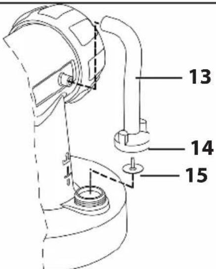
The units may only be used with a functional valve. If paints rises in the ventilating hose (Fig. 12 A, item 14) do not operate the unit further! Dismantle and clean the ventilating hose, valve and diaphragm and replace the diaphragm if necessary.
Do not lay the spray gun.
The device is equipped with a thermal release which disconnects the device in case of overheating. In this case, turn off the device, remove the plug and let the device cool down for at least 1/2 hour. Eliminate the cause of heating, e.g. bent hose, soiled air filter, slots for air intake covered.
With original WAGNER accessories and spare parts, you have the guarantee that all safety regulations are fulfilled.
| Technical Data | |
| Max. viscosity 170 DIN-s | |
| Max. flow rate 240 g/min | |
| Power source 230 - 240 V | ~ |
| Power consumption 570 W | |
| Atomizing output: 130 W | |
| Double insulation | ☐ |
| Sound pressure level 80 dB (A) | |
| Oscillation level < 2,5 m/s ^2 | |
| Air hose length 7,5 m | |
| Weight 13,6 kg | |
TechnDat_GB
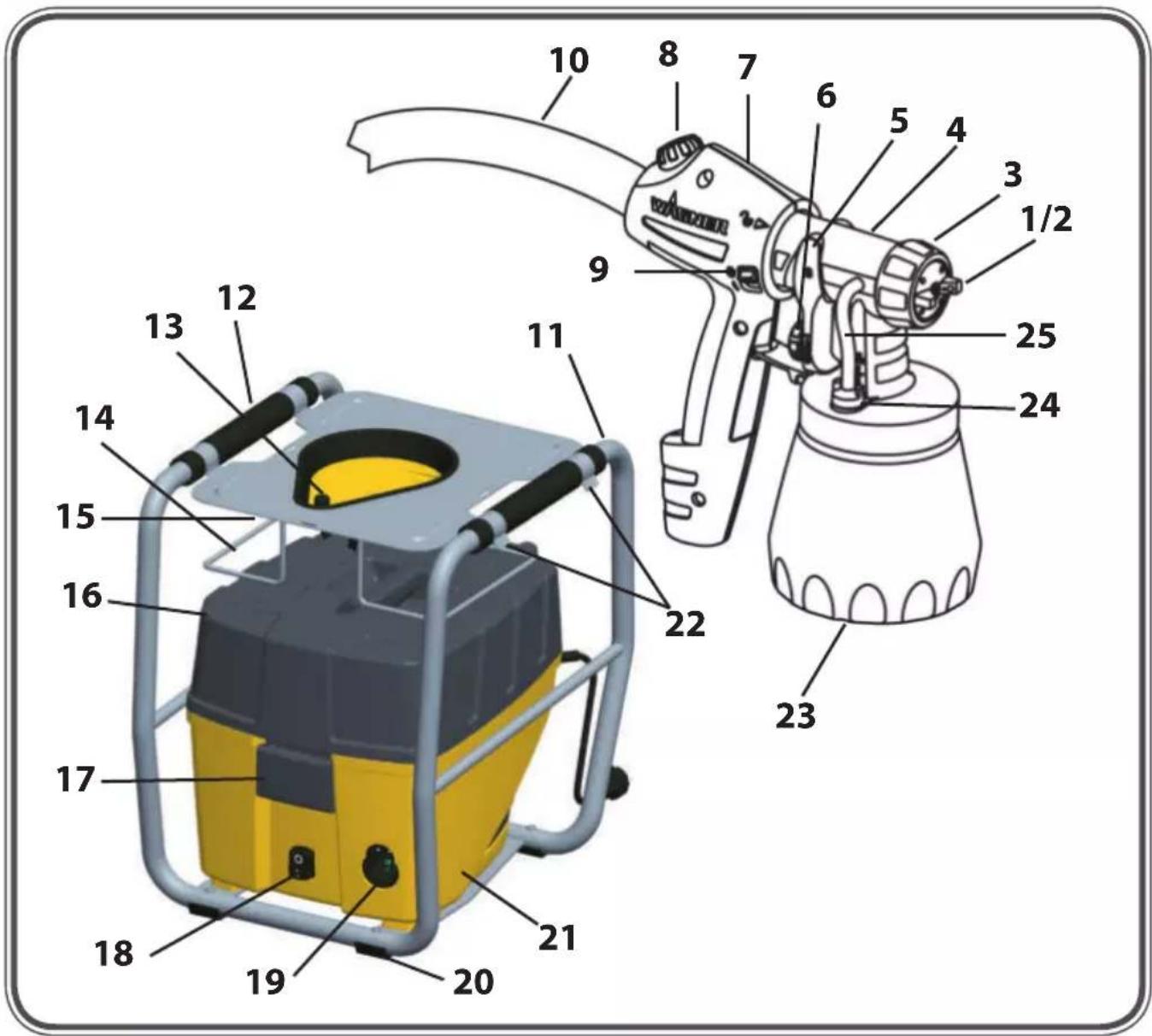
| Description (Figs. 1+2) | |
| Air cap 1) | 2) Tip |
| 3) Union nut | 4) Standard spray attachment |
| 5) Trigger guard | 6) Material volume regulation |
| 7) Gun handle | 8) Air volume control |
| 9) ON/OFF switch | 10) Air hose |
| 11) Frame | 12) Frame carry handle |
| 13) Frame cover/ Gun holder | 14) Air hose retainer |
| 15) Fastening belts for air hose | 16) Basic device cover |
| 17) Basic device closure | 18) Main switch |
| 19) Air hose connection | 20) Frame base |
| 21) Basic device | 22) Frame closure |
| 23) Container | 24) Valve |
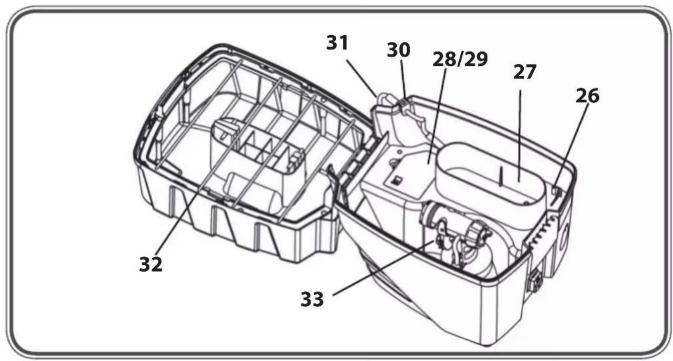
| 25) Ventilating hose | 26) Fastener for radiator/detail spray attachment (accessory |
| 27) Deposition tray for hardware | 28) Cover of air filter compartment |
| 29) Air filter | 30) Cable grommet |
| 31) Power cable | 32) Rubber band |
| 33) Deposition tray for spray attachments | |
Jet Air
With Wagner's new "Jet Air" technology, nozzle and air cap have small indentations which cause air turbulence. This enables the use of aerodynamic advantages similar to those of a golf ball, which result in an optimised air flow and consequently a better spray pattern.
Spray attachment
Brilliant spray attachment (Air cap, blue)
→ Optimised nozzle and air guidance for brilliant paint results
Perfect Spray 800 spray attachment (Air cap, red)
→ For medium- and large-scale objects and furniture.
Coating Materials Suitable for Use
Water- and solvent-based paints, finishes, primers, 2-component paints, clear finishes, automotive finishes, staining sealers and wood sealer-preservatives.
Coating Materials Not Suitable for Use
Wall paints (emulsion paints) etc., alkali and acidic paints. Coating materials with a flash point below 21°C.
Preparation of the Coating Material
The enclosed spray attachment can be used to spray paints, varnishes and glazes that are undiluted or slightly diluted. Detailed information is available in the technical data sheet of the manufacturer ( Internet download).
- Stir the material up and put the required amount into the paint container.
| Thinning recommendation | |
| Sprayed material | |
| Glazes undiluted | |
| Wood preservatives, mordants, oils, disinfection agents, plant protective agents | undiluted |
| Paints containing solvents and water-soluble paints, primers, vehicle coating paints, thick-film glazes | dilute by 5 - 10% |
- If the convey capacity is too low, add 5 - 10% dilution step-by-step until the convey capacity fulfils your requirements.
Start-up
Before connecting to the mains supply, be sure that the supply voltage is identical with the value given on the rating plate.

ATTENTION: Do not sit or stand on the device. Danger of tilting/breaking!
- Place the device only on a plane and clean surface. Otherwise, the gun may suck in dust, etc
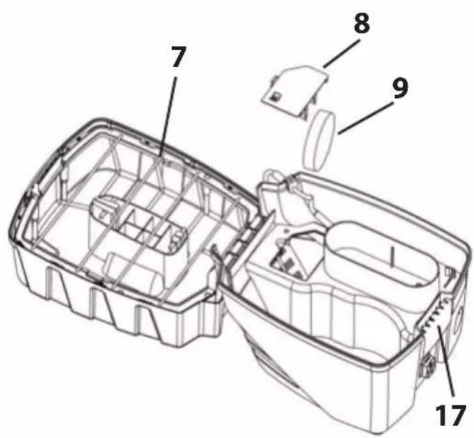
Open the frame at the side closures (Fig. 1, Item 22) and fold it open.2.
- Always lower the handle in the cover before opening the basic device cover (Fig. 1. Item16).
Open the closure (Fig. 1, item 17) and fold open the cover of the basic device. 4.
Unroll the power cable and slide the cable grommet into the provided recess (Fig. 4).5.

ATTENTION: Do not close the cover if the cable grommet is not positioned correctly. The power cable could otherwise be damaged!
Remove the spray attachment from the deposition tray. Unscrew the container from 6. the spray attachment.
Align the ascending tube. (Fig. 5) 7.
If the ascending tube is positioned correctly, the container contents can be sprayed without almost any residue. When working on lying objects: Turn the ascending tube forwards. (Fig. 5A)
Spraying work when working on overhead objects: Turn the ascending tube rearwards. (Fig. 5B)
- Place the container on a paper base and fill in the prepared coating material.
Screw the container firmly onto the spray attachment.
Reclose the cover of the basic device with the lowered carry handle.9.
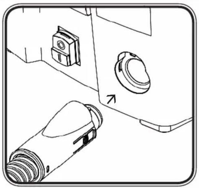
Open the Velcro fasteners (Fig. 1, Item 15) und unroll the air hose. Connect it to the 10. air hose connection (Fig. 3).
Close the frame again11.
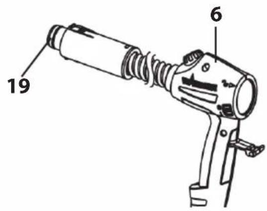
Connect the front part of the gun and the gun handle to each other. (Fig. 6)12.
- Put the spray gun onto the gun holder (Fig. 1, Item 13).
- Switch on the main switch at the device (Fig. 1, item 14).
- Remove the spray gun from the gun holder and point it at the object to be coated.

ATTENTION: It is advisable to test spray cardboard or a similar material in order to determine the material and amount of air for an optimal spray pattern.
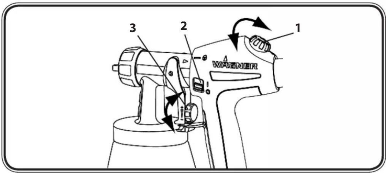
- Press the On/Off switch at the gun handle (Fig. 7, item 2).
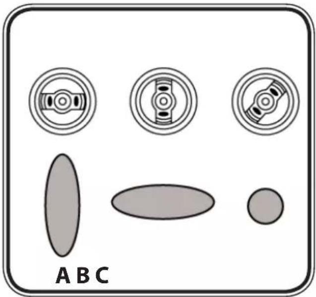
Three different spray jet settings can be chosen on the spray gun, depending on the application and target object.
Selecting the Spray Setting
Fig. 8 A = horizontal flat jet → for horizontal surfaces
Fig. 8 B = vertical flat jet → for vertical surfaces
Fig. 8 C = circular jet → for corners, edges and hard-to-reach surfaces
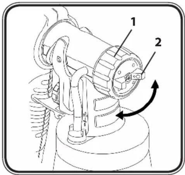
Adjusting the desired Spray Setting (Fig. 9)
With the union nut (1) slightly unscrewed, turn the air cap (2) to the desired spraysetting position (arrow). Then tighten the union nut.

WARNING!
Danger of injury! Never pull the trigger guard while adjusting the air cap.
Adjusting the Material Volume (Fig. 7, item 3)
Set the material volume by turning the regulator on the trigger guard of the spray gun.
- turn to the left → lower material volume
+ turn to the right higher material volume
Setting the Amount of Air (Fig. 7, item 1)
Depending on the viscosity of the material to be sprayed and the finish of the object to be coated, it may be advisable to vary the amount of air. Very low viscosity materials, such as watery glazes do not have to be atomised with the maximum amount of air. In this case it is advisable to reduce the amount of air and thus minimize the spray vapour.
This also applies for the use of the low-scale and radiator/detail spray attachment (accessory).
- turn to the left → lower amount of air
+ turn to the right higher amount of air
Spray Technique
The spray result depends heavily on the smoothness and cleanliness of the surface to be sprayed. Therefore the surface should be carefully prepared and kept free of dust.
Cover all surfaces not to be sprayed.
Cover screw threads or similar parts of the target object.
It is advisable to test the spray gun on cardboard or a similar surface to find the correct setting.
Important: Begin spraying outside of the target area and avoid interruptions inside the target area.
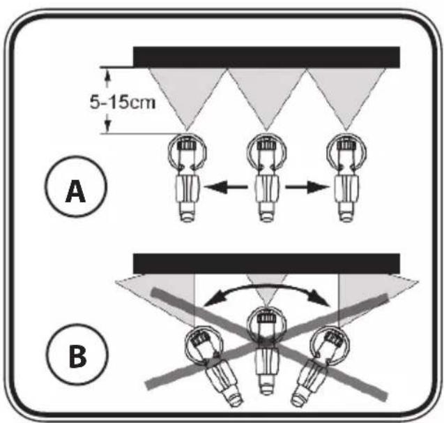
The spray movement should come from the arm, not just from the wrist. This ensures that a uniform distance is maintained between the spray gun and the spray surface during the spray operation. Select a distance of 5 - 15 cm, depending on the desired spray jet width.
Fig. 10 A: CORRECT: Even distance to the object.
Fig. 10 B: INCORRECT: Uneven distance causes uneven coating.
Move the spray gun evenly cross-wise or up-and-down, depending on the spray pattern setting.
An even movement of the spray gun results in an even surface quality.
When coating material builds up on the nozzle and air cap (Fig. 10), clean both parts with a solvent or water.
Interruption of Work till 4 Hours
Turn the machine off.
Vent the container. This can be done by briefly turning open and then closing the container or by pulling the trigger guard and letting the paint into the original paint container.
Insert the spray gun into the gun holder.
When processing 2-component varnishes, clean the device immediately.
Taking Out of Operation and Cleaning
Proper cleaning is the prerequisite for problem-free operation of the paint application device. No warranty claims are accepted in case of improper or no cleaning.
Turn the machine off.1)
Divide the spray gun. Press the hook (Fig. 6 "click") slightly downwards. Turn the gun 2)
front part and gun rear part against each other.
3) ATTENTION: Never hold the gun handle under water or immerse it into liquids. Clean the housing only with a moistened cloth.
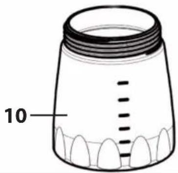
Unscrew the container. Empty any remaining coating material back into the material 4) tin.
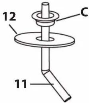
Preclean the container and feed tube with a brush. Clean the ventilating bore (Fig.11, 5) item C).
6) Pour solvent or water into the container. Screw the container back on. Use only solvents with a flashpoint over 21°C.
Assemble the gun again (Fig. 6).7)
Turn on the machine and spray the solvent or water into a container or a cloth.8)
9) Repeat the above procedure until the solvent or water emerging from the nozzle is clear.
Turn off the machine and divide the spray gun.10)
Screw of the container and empty it. Pull out the suction tub with container seal.11)

CAUTION! Never clean seals, diaphragm and nozzle or air holes of the spray gun with metal objects.
The ventilation hose and diaphragm are only solvent-resistant to a limited extent. Do not immerse in solvent, only wipe.
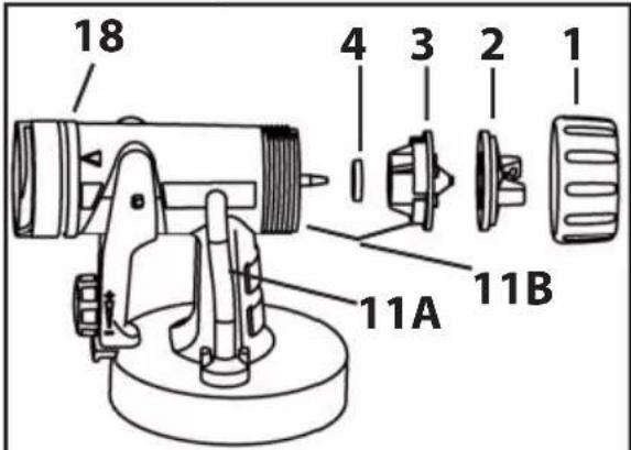
Pull the ventilating hose (Fig.11 A, item 13) at the top from the gun body. Screw off 12) the valve cover (14). Remove the diaphragm (15). Clean all the parts carefully.
Unscrew the union nut and remove the air cap and nozzle. Clean the air cap, nozzle 13) seal and nozzle with a brush and solvent or water (Fig. 11, item 5).
Clean the outside of the spray gun and container with a cloth soaked in solvent or 14) water.
15) Assemble the parts again (see "Assembly").
Assembly
The unit may only be operated with an integer diaphragm (Fig. 11A, item 15). Place the diaphragm with the pin facing upwards on the bottom section of the valve. Also see the marking on the gun body. Place on the valve cover and screw it closed. Place the ventilating hose on the valve cover and on the nipple at the gun body.
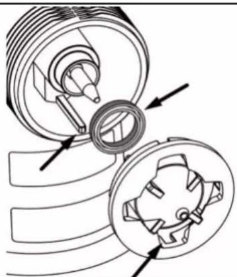
Slide the nozzle seal (Fig. 11, item 4) with the groove (slot) facing forwards into the nozzle (Fig. 11B). Put the nozzle onto the gun body and find the correct position by turning it. Put the air cap onto the nozzle and tighten it using the union nut.
Place the container seal from below on the suction tube and slide it over the collar, while turning the container seal slightly. Insert the suction tube with container seal in the gun body.
Maintenance

WARNING!
Never operate the machine without the air filter; dirt could be sucked in and interfere with the function of the machine. Do not store any objects in the air filter compartment.
Change the air filter if it is soiled. Unplug the power plug. Open the cover of the air filter compartment (Fig. 12). Insert a new air filter into the compartment. Close the cover of the air filter compartment.
In order to mount the gun more easily apply lubricating grease (enclosed) liberally to the
O-ring at the spray attachment (Fig. 11, item 18) and to the O-ring of the plug connection of the air hose (Fig. 11, item 19).
Storage
Remove the hose and when storing it in the cover put in the gun handle first.
| Spare Parts List (Fig. 12) | ||
| Pos. | Designation Order No. | |
| 1 | Union nut 0417 319 | |
| 2 | Air cap (Brilliant, blue) | 0414 384(0414 387) |
| Air cap (Perfect Spray 800, red) | 0414 368(0414 378) | |
| (Australia version spare part no. in brackets) | ||
| 3 | Nozzle (Brilliant, blue) | 0414 381 |
| Nozzle (Perfect Spray 800, red) | 0417 349 | |
| 4 | Nozzle seal 0417 706 | |
| 5 | Brilliant Spray attachment complete with 800 ml aluminium container (Australia version spare part no. in brackets) | 2304 006(2304 007) |
| 6 | Gun handle with air hose (7,5m) 0420 704 | |
| 7 | Rubber band 0420 259 | |
| 8 | Cover of air filter compartment 0420 328 | |
| 9 | Air filter 0420 702 | |
| 10 | Container with cover 800 ml (aluminium) 0420 708 | |
| 11 | Suction tube 0417 357 | |
| 12 | Container seal 0417 358 | |
| 13 | Ventilating hose | 0417 927 |
| 14 | Valve cover | |
| 15 | Diaphragm | |
| 16 | Lubricating grease | 9892 550 |
| 17 | Closure | 0420 701 |
| 18 | O-ring of spray attachment | 0417 308 |
| 19 | O-ring of air hose | 0420 316 |
| Spare Parts List (Fig. 1) | ||
| 11 | Frame | 0420 244 |
| 12 | Frame carry handle (2x) | 0420 707 |
| 13 | Frame cover/ Gun holder | 0420 706 |
| 15 | Fastening belts for air hose (2x) | 0420 703 |
| 20 | Frame base (4x) | 0420 705 |
The new CLICK&PAINT SYSTEM with additional spray attachments and accessories offers the richt tool for each work.
| Accessories (not included in the delivery) | |
| Name Order No. | |
| Container with cover 800 mlEnsures that the paint does not dry out and the solvent does not evaporate. | 0413 909 |
| Brilliant spray attachment incl. 800 ml aluminium containerOptimised nozzle and air guidance for brilliant paint results | 2304 006AUS (2304 007) |
| Perfect Spray spray attachment incl. 800 ml. aluminium containerFor a rapid paint change. For medium- and large-scale objects and furniture. | 0420 709AUS (0420 710) |
| Small-scale spray attachment incl. 250 ml containerFor fi ligree objects, detailed and creative work. | 0417 918AUS (0417 924) |
| Perfect Spray spray attachment incl. 1400 ml containerRapid working at larger objects such as timber houses, garage doors, etc. | 0417 917AUS (0417 923) |
| Detail / Radiator spray attachment incl. 600 ml containerFor inaccessible places, such as radiators, cupboard corners, recesses etc. | 0417 915AUS (0417 925) |
Further information about the WAGNER range of products for renovating is available under www.wagner-group.com
Environmental protection
The appliance and accessories should be recycled in an environmentally friendly way. Do not dispose of the appliance with household waste. Support environmental protection by taking the appliance to a local collection point or obtain information from a specialist retailer.
Important Note regarding Product Liability!
Due to an EC ordinance in effect since 01.01.1990, the manufacturer is liable for his product only if all parts originate from or were approved by the manufacturer and the devices are assembled and operated correctly. The use of other accessories and spare parts can partially or completely invalidate the liability.
Correction of Malfunctions
| Malfunction Cause Remedy | ||
| Coating material drips from the nozzle | Coating material assembly at air cap, nozzle or needleNozzle looseNozzle seal wornNozzle worn | CleanUnion nut tightenChangeChange |
| Malfunction Cause Remedy | Remedy | |
| No coating material emerges from the nozzle | Nozzle cloggedMaterial volume setting turned too far to the left (-)No pressure build-up in containerContainer emptyFeed tube looseFeed tube clogged | CleanTurn to the right (+)Tighten containerRefillInsertClean |
| Atomisation too coarse M | Material volume too largeMaterial volume adjusting screw turned too far to the right (+)Nozzle contaminatedViscosity of coating material too highToo little pressure build-up in containerAir filter heavily soiledAmount of air too low | Turn material volume adjusting screw to the left (-)CleanAdd 5 - 10% dilutionTighten containerChangeTurn the air volume control to the right (+) |
| Spray jet pulsates Coating | material in container running outNozzle seal wornAir filter heavily soiled | RefillReplaceChange |
| Coating material causes "paint tears" | Too much coating material applied. Turn material volume adjusting screw to the left (-) | |
| Too much fog of coating material (Overspray) | Distance to the object too largeToo much coating material appliedAmount of air too high | Reduce distanceTurn material volume adjusting screw to the left (-)Turn the air volume control to the left (-) |
| Paint in the ventilating hose | Diaphragm soiledDiaphragm defective | Clean the diaphragmReplace the diaphragm |
| Device does not function | Device overheated Unplug the power plug, let the device cool down approx. 30 minutes, do not bend the hose, check the air filter, do not cover the intake slots | |
Warning
If the supply cord of this appliance is damaged, it must only be replaced by a repair shop appointed by the manufacturer, because special purpose tools are required.
Warning: Do not connect the blue or brown wire to the earth terminal of the plug! The wires in this mains lead are coloured in accordance with the following code:
blue = neutral brown = live
As the colours of the wires in the mains lead of this appliance may not correspond with the coloured markings identifying the terminals in your plug, proceed as follows:
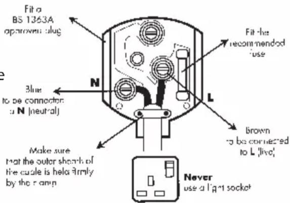
◆Should the moulded plug have to be replaced, never re-use the defective plug or attempt to plug it into a different 13 A socket. This could result in an electric shock.
- Should it be necessary to exchange the fuse in the plug only use fuses approved by ASTA in accordance with
BS 1362. 5 Amp fuses may be used.
◆ To ensure that the fuse and fuse carrier are correctly mounted please observe the provided markings or colour coding in the plug.
◆After changing the fuse, always make sure that the fuse carrier is correctly inserted. With out the fuse carrier, it is not permissible to use the plug.
◆ The correct fuses and fuse carriers are available from your local electrical supplies stockist.
Guarantee declaration
The guarantee period amounts to 24 months in case of private use, and to 12 months in case of commercial use. If the amount of paint processed with the unit exceeds 1,000 litres, this is considered to be commercial use.
We give a works guarantee to the following extent for this unit:
All those parts that prove to be unserviceable or to be considerably impaired in their serviceability within the guarantee period since the point of handing over to the buyer due to a circumstance lying before this handing over – in particular due to faulty design, bad building materials or poor execution – are improved or supplied new as we choose without costs.
We do not accept any guarantee for damage that has been caused by the following reasons:
Unsuitable or incorrect usage, faulty mounting or starting-up by the buyer or by third parties, natural wear - wear parts are not covered by the WAGNER guarantee, faulty handling in particular inadequate cleaning or maintenance, unsuitable coating materials, substitute materials and chemical, electrochemical or electrical influences, in as far as damage is not due to our fault. Abrasive coating materials, such as dispersions, glazes, quartz undercoats, abrasive materials, etc. reduce the durability of valves, packings, spray guns, tips, cylinders, pistons, filters, hoses, seals, etc.
Any resulting signs of wear are not covered by this guarantee. The unit is not conceived for use in shift work or for lending or leasing – these uses are excluded from the guarantee.
The replacement of a part does not extend the guarantee period of the unit.
The unit has to be examined immediately after receipt. Obvious faults are to be reported in writing within 14 days after receipt of the unit in order to avoid loss of the rights arising from faults.
We reserve the right to have the guarantee fulfilled by a contractual company.
Repairs going above and beyond those dealt with in these operating instructions are reserved for our factory. In case of a guarantee case or repair, please contact the specialist dealer from whom you purchased the unit.
Fulfilling of the guarantee depends on proof being provided by invoice and delivery note or proof of purchase.
If the check shows that the case is not a guarantee case, repairs are carried out at the expense of the buyer.
Claims against Wagner that are based on or caused by the failure or insufficiency of a unit cannot be asserted.
We make it clear that the guarantee declaration does not represent a limitation of the statutory rights or of the rights agreed contractually through our general terms of business.
Mode d'emploi
Declaration of Conformity
We declare under sole responsibility that this product conforms to the following relevant stipulations: 73/23/EWG, 89/336 EWG; 2002/95/EG; 2002/96/EG
Applied harmonised norms:
EN 55014-1: 2002, EN 55014-2: 2001, EN 61000-3-2/2005, EN 61000-3-3:2001,
EN 60335-1:2004

D-88677 Markdorf Managing Director Development Manager
| D | J. Wagner GmbHOtto-Lilienthal-Str. 18D-88677 MarkdorfHotline 0180/1000 227+49/75 44 /505-0 +49/75 44/505-200 |
| B | Wagner Spraytech BelgieVeilinglaan 581861 Meise-Wolvertem |
| +32/2/2 69 46 75 +32/2/2 69 78 45 |
© Copyright by J.Wagner GmbH
| CZ | Wagner Spol s.r.o. |
| Nedašovská 345 | |
| 15500 Praha 5 | |
| +420/2/57 95 04 12 +420/2/57 95 10 52 |
| E | J. Wagner Spraytech Ibérica S.A.Ctra. N-340, Km 1245,408750 Molins de Rei (Barcelona) |
| +34/93/6 80 00 28 +34/93/6 68 01 56 |
| SLO | Adresa servisa:GMA Elektromehanika d.o.o. |
| Cesta Andreja Bitenca 115,Ljubljana 1000/Slowenien | |
| +386(1)/583 83 04 +386(1)/518 38 03 |
Not responsible for errors and changes.


- ProjectPro
- Extra
- D/GB/F/NL
- ProjectPro 213 Extra
- Bedienungsanleitung
- Operating instruction
- General Safety Instructions
- Caution!
- Workplace
- Electrical Safety
- Safety of Persons
- Careful Handling and Use of Power Tools
- Service
- Safety Instructions for Spray Guns
- ATTENTION! EXPLOSION HAZARD!
- CAUTION: Danger of injury! Never point the spray stream towards human beings or animals.
- Jet Air
- Spray attachment
- Coating Materials Suitable for Use
- Coating Materials Not Suitable for Use
- Preparation of the Coating Material
- Start-up
- ATTENTION: Do not sit or stand on the device. Danger of tilting/breaking!
- ATTENTION: Do not close the cover if the cable grommet is not positioned correctly. The power cable could otherwise be damaged!
- ATTENTION: It is advisable to test spray cardboard or a similar material in order to determine the material and amount of air for an optimal spray pattern.
- Selecting the Spray Setting
- Adjusting the desired Spray Setting (Fig. 9)
- WARNING!
- Adjusting the Material Volume (Fig. 7, item 3)
- Setting the Amount of Air (Fig. 7, item 1)
- Spray Technique
- Interruption of Work till 4 Hours
- Taking Out of Operation and Cleaning
- Assembly
- Maintenance
- Never operate the machine without the air filter; dirt could be sucked in and interfere with the function of the machine. Do not store any objects in the air filter compartment.
- Storage
- Environmental protection
- Important Note regarding Product Liability!
- Warning
- Guarantee declaration
- Mode d'emploi
- Declaration of Conformity
Brand : WAGNER
Model : ProjectPro 213 Extra
Category : Paint spray