C-IR 20 - Thermostat BOSCH - Free user manual and instructions
Find the device manual for free C-IR 20 BOSCH in PDF.

| Product type | Control thermostat for infrared electric heating |
| Brand | Bosch |
| Model | C-IR 20 |
| Dimensions (L x H x D) | 91 mm x 91 mm x 42 mm |
| Power supply | 230 VAC, 16 A max, backup battery 1 x ML 1220 |
| Power consumption | ~2.5 W |
| Control type | PID (cycle 10 min) or hysteresis +/- 0.3 °C |
| Set temperature range | 5 °C to 37 °C in 0.5 °C steps |
| Frost protection | Automatic below 7 °C (adjustable from 2 °C to 15 °C) |
| Operating modes | Manual, Timer, Program, OFF, Frost, Holiday |
| Open window function | Automatic detection and heating stop for 15 minutes |
| Screen lock | Yes, activation via menu Settings > Display > Screen lock |
| Early start | Yes, can be activated in the Program menu |
| Probe calibration | Yes, accessible via installation > Probe |
| Protection rating | IP20, class II |
| Maximum load | Relay 16 A, 250 VAC (resistive load only) |
| Display | Touch screen, adjustable color (blue, red, green, none) |
| Weekly programming | 4 included programs + 3 customizable user programs |
| Maintenance | Screen cleaning via menu; backup battery not user-replaceable |
| Safety | Screen lock, frost protection, open window function |
Frequently Asked Questions - C-IR 20 BOSCH
User questions about C-IR 20 BOSCH
0 question about this device. Answer the ones you know or ask your own.
Ask a new question about this device
Download the instructions for your Thermostat in PDF format for free! Find your manual C-IR 20 - BOSCH and take your electronic device back in hand. On this page are published all the documents necessary for the use of your device. C-IR 20 by BOSCH.
USER MANUAL C-IR 20 BOSCH
en Thermostat control Installation and operating instructions ..... 29
natural_image
Line drawing of a Bosch rectangular device with a central square frame and circular logo (no text or symbols on the device itself)Inhaltsverzeichnis
3 Installation .....10
natural_image
Simple line drawing of a trash bin with crossed lines indicating no waste or discharge (no text or symbols)1 Explanation of symbols and safety instructions ..... 31
1.1 Explanation of symbols ..... 31
1.2 Safety instructions ..... 32
2 Product Information .....33
2.1 Scope of delivery ..... 33
2.2 Product Description ..... 34
2.3 Intended use ..... 34
2.4 Product overview ..... 34
2.5 Specifications ..... 35
3 Installation ..... 37
3.1 Prior to installation ..... 37
3.2 First installation ..... 37
3.2.1 Mounting instruction ..... 37
3.3 Installing the control ..... 38
3.4 Electrical connection ..... 38
4 Parameter's precision ..... 39
5 Operation .....41
5.1 Display ....41
5.2 Overview of the control .....41
5.3 Installation menu .....42
5.4 Mode of operation ..... 43
5.5 Special function .....45
6 Diagnosis and troubleshooting ..... 47
6.1 Troubleshooting .....47
7 Environmental protection and disposal .....48
8 Appliance maintenance .....50
8.1 Battery replacement .....50
9 Overview Main menu .....51
1 Explanation of symbols and safety instructions
1.1 Explanation of symbols
Warnings
In warnings, signal words at the beginning of a warning are used to indicate the type and seriousness of the ensuing risk if measures for minimising danger are not taken.
The following signal words are defined and can be used in this document:

DANGER
DANGER indicates that severe or life-threatening personal injury will occur.

WARNING
WARNING indicates that severe to life-threatening personal injury may occur.

CAUTION
CAUTION indicates that minor to medium personal injury may occur.
NOTICE
NOTICE indicates that material damage may occur.
Important information

The info symbol indicates important information where there is no risk to people or property.
Additional symbols
Symbol Meaning
▶ a step in an action sequence
→ a reference to a related part in the document
a l i s t e
- a list entry (second level)
Table 7
1.2 Safety instructions

CAUTION
Risk of corrosion due to leaking batteries
If the product is not in operation for several weeks, there is a risk that the batteries start leaking. The battery fluid can cause corrosion.
▶ Remove the batteries during longer periods of absence.
▶ Use a corrosion resistant means of protection when removing leaking batteries.

CAUTION
Damage due to incorrect connection.
The device may be damaged if this product is connected incorrectly.
The thermostat power supply must be disconnected when inserting the display part (the screen) into the base or removing it from the base.
▶ Only have the product installed by an authorised professional.

CAUTION
Before starting work, disconnect the power supply.
▶ Only have the product installed, connected and commissioned by an authorised professional.
▶ All installation and wiring work related to the product must be carried out only when de-energized.
▶ Make sure to adhere to valid safety regulations.
▶ Do not interchange the connections of the sensors and the 230V connections under any circumstances. Doing so may result in life endangering electrical hazards or the destruction of the appliance and the connected sensors and other appliances.
- Do not switch off the thermostat's power supply outside the heating season. It may shorten the lifespan of the standby battery. Only switch off the heating using the thermostat's Switched Off mode.

The thermostat is neither splash- nor drip-proof. Therefore, it must be mounted at a dry place.
2 P r o d u c t l n f o
2.1 Scope of delivery
The scope of delivery is shown in Fig. 1 at the end of the document:
[1] Thermostat control
[2] Frame
Installation instructions
2.2 Product Description
You can set the required temperature of a room easily and precisely (to the nearest half degree). Thanks to the sensors integrated in the thermostat, you can quickly set a temperature in each room that is comfortable for you. A time-controlled temperature program can also be set for every room. An automatic frost protection program starts at temperatures below 7 °C.
2.3 Intended use
The thermostat is developed to control and manage all type of heating installations. It has been designed for use in residential rooms, office spaces and industrial facilities.
▶ Make sure the product is adjusted correctly by following the safety instructions and other directions in these operating instructions.
▶ Make sure the installation complies with existing regulations before operation to ensure proper use of the installation.
▶ The technical data must be taken into account.
- Avoid installation in areas exposed to intense sunlight or in dust-laden environments.
▶ Do not make any modifications to the product.
2.4 Product overview
The overview is shown in Fig. 1 at the end of the document.
The touch-screen thermostat is specially designed to control the infrared panels. The thermostat will allow to optimize the energy consumption and increase the comfort levels.
It offers the following functions:
• Modern design with touch-screen
• Simplified wiring and installation
- "Easy program creation" function
- Fully program m a b l e
• Temporary override function
- Anti-freeze function
• Holiday or Reception function
• Estimation of the cost and consumption of the installation
2.5 Specifications

This product conforms to European directives and supplementary national requirements in design and operation. Compliance is demonstrated by the CE marking.
You can request the conformity declaration of the product. If you require this, contact the address on the back cover of these instructions.
| Purpose of control Thermostat | |
| Control construction Electronic independently mounted control | |
| Screwless terminal method of disconnection | Type X |
| Action type Type 1 only | |
| Batteries 1 x ML 1220 | |
| Power consumption ~2.5W | |
| Regulation characteristics PID (10 min cycle for load command) or Hysteresis of 0,5 °C | |
| Protection IP20, class II | |
| Sensing element extension Temperature | |
| Measured temperature precision 0,1 °C | |
| Environmental temperature: | |
| Operating temperature | 0°C to -40°C |
| Shipping and storage temperature | -10°C to +50°C |
| Setting temperature range | |
| Comfort, Reduced | 5°C to 37°C by 0,5°C step |
| Holiday /Antifreeze) | 7°C (adjustable) |
| Control pollution degree 2 | |
| Maximum load Relay 16 Amps, 250VAC | |
| Rated impulse voltage | 2500V |
| External load type | Resistive only |
| Dimensions(width x height x depth) | 91 mm x 91 mm x 42 mm (for more dimensions → Fig. 2 at end of document) |
| Battery time 24 hours minimum (battery fully charged) | |
| Software class Class A | |
| Software version Displayed in the user menu | |
| Ball pressure test temperature | 125 °C (for the plastic part that weights the current/power supply)75 °C (for the other plastic parts) |
Table 8
| Type of heat transfer/room temperature-dependent control | |||
| Electronic room temperature-dependent control with week timer | -- Yes | ||
| Other control options | |||
| Room temperature-dependent control with presence detection | -- No | ||
| Room temperature-dependent control with open-window detection function | - | - | Y |
| Room temperature-dependent control with remote control option | -- No | ||
| Room temperature-dependent control with adaptive control of heating start | - | - | Y |
| Room temperature-dependent control with operating time limit | -- Yes (timer) | ||
| Room temperature-dependent control with black ball sensor | - | - | N o |
3 Installation
3.1 Prior to installation
▶ Carefully read the technical documentation and make sure all instructions contained therein are understood and observed.
The thermostat should be mounted, operated and maintained by specially trained personnel only. Personnel in the course of training are only allowed to handle the product under the supervision of an experienced fitter.
▶ Observe the scheme of connection ( Fig. 6).
▶ Observe the dimensions of the thermostat ( Fig. 2).
▶ Install it far from heat sources.
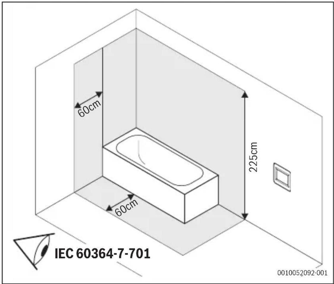
▶ Ensure a minimum distance of 20 cm between the thermostat and doors and 1,5 meters from floor ( Fig. 5).
▶ Ensure that there is air circulation.

The manufacturer shall not be liable in case of incompetent use of the thermostat. Any modifications and amendments are not allowed for safety reasons.
3.2 First installation

WARNING
The thermostat is intended for connection to the electric infrared heater. The installation must ensure that the PE connection (protective earth) on the infrared heater is correctly connected.
The thermostat can be loaded with a maximum of 3600 W (16 A) (Fig. 7). Above this power, an external power relay (contactor) must be installed for optimisation to maintain good control (Fig. 8).
3.2.1 Mounting instruction
- All electrical conduits to the thermostat box that contain heating cable must be sealed to protect the thermostat against hot air currents.
Dimensions
The dimensions are shown in Fig. 2 at the end of the document.
Clearances
The clearances are shown in Fig.5 at the end of the document.
3.3 Installing the control
The installation steps and electrical connection are shown in Fig. 3 at the end of the document.
The electrical connection is shown in Fig. 6 and, according to the power used, Fig. 7 or Fig. 8 at the end of the document.

The thermostat power supply must be disconnected when inserting the display part (screen) into the base or removing it from the base. Failure to follow this instruction may result in an irreparable damage to the thermostat.
3.4 Electrical connection

WARNING
Risk to life from electric shock!
Touching live electrical parts can cause an electric shock.
▶ Before working on electrical parts, disconnect all phases of the power supply (fuse/circuit breaker) and lock the isolator switch to prevent unintentional reconnection.
▶ The electrical circuit in which the thermostat is connected must be protected by a circuit breaker with a tripping current of max. 16A.
4 Parameter's precision

The default values are highlighted in bold in the following table.
| Parameters Position on menu structure | Description |
| DST Date and Time Daylight Summer Time change between Summer and WinterYes- automatic change according to dateNo - no daylight summer time automatic change | |
| OFF Screen Period | Display This parameter allows the user to set when the display must be completely shut off.Default OFF Screen Period is between 20 pm to 7 am. |
| Parameters Position on menu structure | Description | |
| Sensor Calibration | Installation > Sensor | The calibration must be done after one day of working with the same setting temperature in accordance with the following description:► Put a thermometer in the room at 1,5 m distance from the floor and check the real temperature in the room after one hour.► Then, select the sensor you wish to calibrate.► Use the (-) or (+) keys to enter the real value |
| Only the heating element driven by the thermostat must be used during the complete step of the calibration. | ||
| Calibration can be erased by using the RESET function. | ||
| Sensor Regulation | Installation > Regulation | Air: only internal sensor is used, no floor limitation |
| Regulation Type | Installation > Regulation | ON/OFF: regulation made by hysteresis +/- 0,3°C.PID: use a PID regulation. |
| Smart Start Installation > Regulation | The function can be activated/deactivated: in Program Menu, the positive steps will be anticipated according to the current temperature and the next step point. | |
Table 9
5 O p e r a t i o n
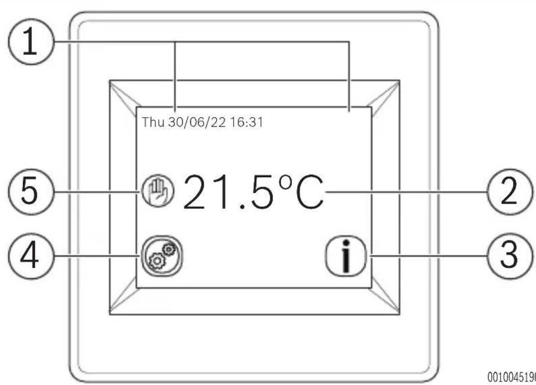
5.1 Display
The display is shown in Fig. 9 at the end of the document.
| Articles Symbol Description | ||
| 1 Displays the date and time | ||
| 2 Displays the selected temperature | ||
| 3 | C h e information symbols and description in 5.2. | c k t |
4 Allows the user to access the  | Settings, Mode and Statistics menus. | |
| 5 Check the operating mode symbols and description in 5.2. | Displays the program selected by the user | |
Table 10
5.2 Overview of the control
| Symbol Description | ||
| Operating modes | ||
 | Manual mode | |
 | Sunday's program mode | |
 | Reduce | |
 | Vacation | |
| [A2C2] | Anti Freeze | |
 | ||
 | Timer | |
| Information/warning symbols | ||
| Symbol Description | |
| i | Access to the current set point |
 | Visualization of the current program |
 | Screen Lock |
| Other symbols | |
 | Settings key |
Table 11 Symbols in the display
5.3 Installation menu
The following section will show how to set up the thermostat for the first time.
Language
▶ Press the < or > keys near the flags to select the chosen language. The active language will appear framed.
▶ Press the key in the bottom right corner to continue the settings of the installation process.
Degree Format
Select the degree format chosen by pressing on the touch button near the degrees.
The active option will be shown in coloured red.
▶ Press the key in the bottom right corner to continue to the next part of the installation process.
It is possible to return to the previous menu by pressing the key.
Date and Time
▶ Select the time format 12h or 24h using the same method as mentioned above.
▶ Press the or keys to activate the value to be modified.
Each time a value is highlighted, it can be modified by pressing the + or - keys.
▶ Press the key in the bottom right corner to continue to the next part of the installation process.
It is possible to return to the previous menu by pressing the key.
Heating Power
▶ Press the or keys to select a unit.
▶ Press the + or - keys to modify the heating power.
This value is used to estimate the running cost of the system. It is possible to return to the previous menu by pressing the key.
▶ Press the key in the bottom right corner to continue.
The main screen is displayed.
The default working mode will automatically be set to the Manual mode.
RESET
Press the RESET button for two seconds to reset your installation.
5.4 Mode of operation
▶ Press the key on the main screen.
▶ Press the Mode button to access the operating modes.
▶ Press the or keys to scroll and select a mode. The selected mode will appear framed.
▶ To select a mode, press the key to return to the main screen.
Programmable mode
In this mode, the thermostat will follow the chosen program (Built-in or customized), according to the actual time.
You can temporarily override the selected program by pressing the temperature displayed on the main screen.
The icon will be displayed when the override function is active. To exit override mode, switch to Manual and then back to automatic mode.
There are four built-in programs that cannot be modified and three customizable user programs.
Customize a user program
▶ Press the Mode button, the Ⓛ icon and then Edit Program button and choose a user program.
▶ Then, it is possible to choose between three configurations.
a) Set day by day
A program can be set for each day. The first day will automatically be set to Mon.
The minimum program step is 15 minutes. It is necessary to configure several periods. The first period begins at 00:00.
▶ Choose the end time period with the + and - keys and the temperature to be followed during this period.
▶ Press the Next button to continue the program. The next period will start at the end of the last period.
For all periods defined, an end period needs to be defined as well as temperature. The last period stops at 24:00. Then, press the Next button.
Then, define another program for Tuesday by pressing the EDIT button. It is possible to copy the program set for Mon by pressing Copy to button.
b) Set weekday/weekend
One program needs to be defined for the weekdays (Mon to Fri) and one for the weekend (Sat and Sun).
Use the same process as explained above to customize the program.
c) Set all days at once
One program needs to be defined. It will be the same for every day of the week.
Use the same process as explained above to customize the program.
How to choose a program
▶ Press the Mode button, the Ⓛ icon and then Edit Program button.
▶ Press Select Program and select between four built-in programs and three user programs.
▶ Press See Next to scroll through the different programs and Select to confirm the selection.
The current program can be viewed by pressing View Current Program.
▶ If you return to the main screen, press on the button on the bottom right of the screen to see the current program.
Timer mode
The Timer mode allows to set a temperature and duration for a period of up to 5 hours.
This function can be used to override the program for short periods (reception, etc.).
The temperature and duration can be adjusted (default value is 22^ C).
After validating the choice, the logo appears on the left of the temperature with the remaining duration below.
Manual mode
In manual mode, the set temperature will be followed all the time.
OFF mode
Use this mode to switch off your installation.
i
In this mode, the installation can freeze.
Anti Freeze mode
The antifreeze mode is used to protect your installation against frost.
The default value is 7^ C but can be adjusted between 2^ C and 15^ C.
Vacation mode
It is possible to select a mode during vacation time. There are four possibilities:
The default value is 7^ C but can be adjusted between 2^ C and 15^ C.
- OFF mode
- Anti Freeze mode
- Reduce mode
- Sunday's program mode 🔍: the installation follows Sunday's current program.
▶ Then, select a return date and time.
The logo and date of return are displayed on the main screen.
To cancel the vacation function before the return date, simply change operating mode.
5.5 Special function
Keyboards lock function
Use this function to prevent changes to the settings (in a child room, public area, etc.).
▶ To activate de Key lock function, press Settings > Display > Screen Lock.
▶ The logo will be displayed on the screen.
▶ Press the key and then, press the logo for 7 seconds.
Open Window function
The user activates/de-activates the function in the Open Window function menu.
Conditions of open window detection:
The thermostat detects an "Open window" if the displayed temperature (internal or ambient sensor) decreases by 3°C or more during a 5 minutes period (or less). In this case, the thermostats stops heating for 15 minutes. The function remains active during those 15 minutes so the stop can last more time if the temperature continues decreasing.
Return to normal mode:
The thermostat returns automatically to normal mode after the stop period. The function can be overridden: pressing the screen during the stop heating phase, will display a specific menu asking the user to stop or continue the stop phase.
Special cases:
- This function doesn't work if Thermostat is in OFF / Antifreeze Mode.
- If temperature is less than 10^ C , thermostat will regulate at 10^ C during the stop phase.
Information
On the right bottom corner, a button is displayed. This button is a short-cut depending of the current state of the thermostat:
If a warning logo is displayed:
▶ Press on the icon to access the information screen.
The information screen will provide more information on the current fault.
- If a is displayed: you can access the current set point and change it.
- If a icon is displayed, it means that you are in Programmable mode and you can view the current program directly.
- If a logo is displayed, it means that the screen is locked, pressing the icon will unlock the screen.
6 Diagnosis and troubleshooting
6.1 Troubleshooting
| Error Measures | |
| My thermostat does not start Supply problemCheck if the product is correctly wired.Press the Reset button through the small hole under the product on the bottom right corner.In the case of uneven walls or inadequately embedded wiring boxes, excessive fastening of the installation screws may result in loss of contact with the power supply of the display. | |
| Warning logo is displayed General problemsPress the warning logo on the bottom right corner.More information on the fault is displayed i.e. the sensor or the fault type (error, floor limit,...). If the error refers to the sensor:Check the sensor connectionsCheck Regulation type (Air/Floor/Air + Floor,...) | |
| Error Measures | |
| My thermostat seems to work correctly but the heating does not work correctly | OutputCheck the conneContact your installer. |
| My thermostat seems to work correctly but the temperature in the room was never in accordance with the program | ProgramCheck the ClockIf the temperature steps are too high or the step in the program is too shortContact your in adjust the regulation parameters with your heating system.GeneralCheck the calibration sensor |
Table 12
7 Environmental protection and disposal
Environmental protection is a fundamental corporate strategy of the Bosch Group. The quality of our products, their economy and environmental safety are all of equal importance to us and all environmental protection legislation and regulations are strictly observed.
We use the best possible technology and materials for protecting the environment taking account of economic considerations.
Packaging
Where packaging is concerned, we participate in country-specific recycling processes that ensure optimum recycling.
All of our packaging materials are environmentally compatible and can be recycled.
Used appliances
Used appliances contain valuable materials that can be recycled.
The various assemblies can be easily dismantled. Synthetic materials are marked accordingly. Assemblies can therefore be sorted by composition and passed on for recycling or disposal.
Old electrical and electronic appliances
natural_image
Symbol of a trash bin with crossed lines indicating no waste or discharge (no text or labels)This symbol means that the product must not be disposed of with other waste, and instead must be taken to the waste collection points for treatment, collection, recycling and disposal.
The symbol is valid in countries where waste electrical and electronic equipment regulations apply, e.g. "(UK) Waste Electrical and Electronic Equipment Regulations 2013 (as amended)". These
regulations define the framework for the return and recycling of old electronic appliances that apply in each country.
As electronic devices may contain hazardous substances, it needs to be recycled responsibly in order to minimize any potential harm to the environment and human health. Furthermore, recycling of electronic scrap helps preserve natural resources.
For additional information on the environmentally compatible disposal of old electrical and electronic appliances, please contact the relevant local authorities, your household waste disposal service or the retailer where you purchased the product.
You can find more information here: www.bosch-homecomfortgroup.com/en/company/legal-topics/weee/
Batteries
Batteries must not be disposed together with your household waste. Used batteries must be disposed of in local collection systems.
8 Appliance maintenance

CAUTION
Danger due to electric shock or moving parts
▶ Disconnect the power supply before carrying out any maintenance work.
▶ Have any maintenance steps that are not listed here carried out by an approved installer.
8.1 Battery replacement

WARNING
Risk of explosion due to incorrect battery replacement type.
▶ The battery ML 2020 is not intended to be replaced or removed by the end user.
The battery replacement is shown in Fig.4 at the end of the document.

To reassemble the product, proceed in reverse.
▶ Dispose of used batteries in accordance with local legal requirements.
9 Overview Main menu
The menu items appear according to the order listed below.
Mode
- Manual
- Timer
- OFF
- Anti Freeze
- Vacation
- Vacation settings
- OFF
- Anti Freeze
- Red u c e
- Sunday's program
- Set Return Date
- Program
- Program Menu
- View Current Program
- Mon
- Tue
- Wed
- Thu
- Fri
- Sat
- Sun
- Select Program
- Mon
- Tue
- Wed
- Thu
- Fri
- Sat
- Sun
- Select
- See Next
- Edit Program
- User 1
- User 2
- User 3
- Set Day by day
- Set Weekday/Weekend
- Set All Days at Once
- Previous
- Next
- END
- EDIT
- Copy to
- OK
Settings
- L a n g u a g e
- E n g l i s h
- G e r m a n
- D u t c h
- S p a n i s h
- F r e n c h
- D a t e a n d T i m e
- D a t e / T i m e
- A d v a n c e d
- DST
- Yes
- No
- D i s p l a y
- Colour
- B l u e
- Red
- Green
- None
- Clean Screen
- Screen Lock
- Degree Format
- ℃
- °F
- Time Format
-12h
-24h
- OFF Screen Period
- Installation
- Sensor
- Sensor Calibration
- Regulation
- Sensor Regulation
- Air
- R e g u l a t i o n T y p e
- O N / O F F
- PID
- Smart Start
- Yes
- No
- Open Window function
- Yes
- No
- RESET
Statistics
- View
- View Last Day
- View Months
- View Year
- k Wh Price
- Heating Power
Índice
9 Vista general Menú principal .....78
natural_image
Symbol of a trash bin with crossed lines indicating no waste, and a solid black rectangle below (no text or labels)www.bosch-homecomfortgroup.com/en/company/legal-topics/weee/
Baterías
9 Vista general Menú principal
3 Installation .....90
5.3 Menu installation
natural_image
Simple line drawing of a trash bin with crossed lines indicating no waste or plastic discharge (no text or symbols)natural_image
Simple line drawing of a trash bin with crossed x- and y-axes, no text or symbols present.www.bosch-homecomfortgroup.com/en/company/legal-topics/weee/
Batterijen
natural_image
Symbol of a trash bin with crossed lines indicating no waste, and a solid black rectangle below (no text or labels)natural_image
Line drawing of a device rear panel with connectors and cable (no text or symbols)0010045142-003
7
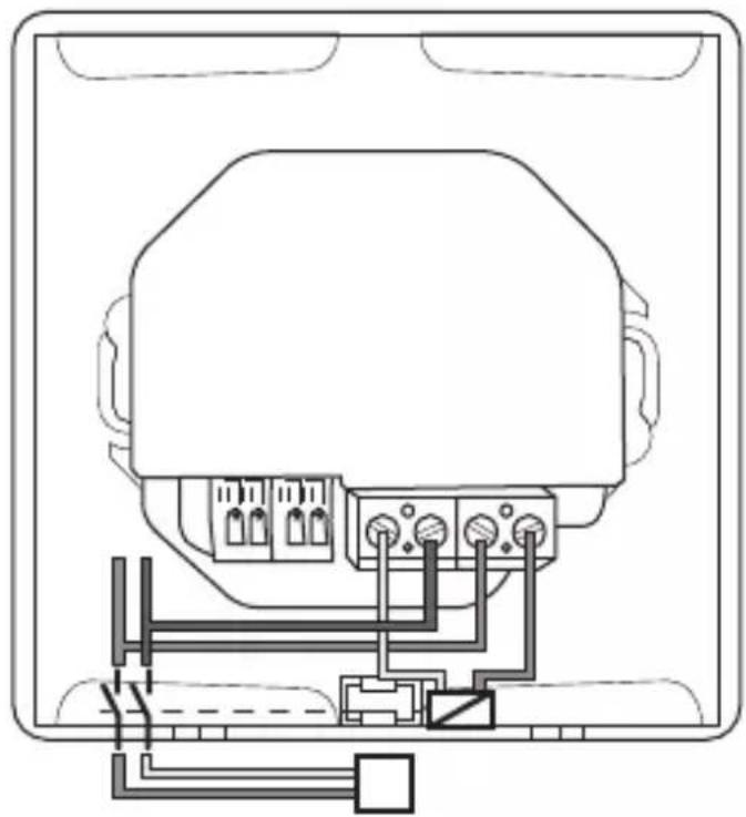
natural_image
Technical line drawing of a device rear panel with connected ports and wiring (no text or symbols)0010045143-002
8


www.bosch-homecomfortgroup.com