TV 431 - Measuring equipment Testboy - Free user manual and instructions
Find the device manual for free TV 431 Testboy in PDF.
| Brand | Testboy |
| Model | TV 431 |
| Product Type | Insulation Tester and Multimeter |
| Dimensions (L x W x H) | 180 x 140 x 65 mm |
| Weight (without batteries) | Approx. 900 g |
| Power Supply | 6 C batteries (Baby or LR14) |
| Battery Life | Approx. 1000 hours |
| Insulation Test Voltages | 250 V, 500 V, 1000 V, 2500 V |
| Insulation Measurement Range | 0.01 MΩ to 100.0 GΩ |
| DC Voltage Measurement | 0.1 V to 1000 V |
| AC Voltage Measurement | 0.1 V to 750 V (50-60 Hz) |
| Resistance and Continuity Measurement | 0.01 Ω to 200.0 Ω |
| Special Functions | Hold, relative measurement, timer, memory (20 slots), comparison, DAR/PI |
| Safety Category | CAT III 1000V / CAT IV 600V |
| Operating Temperature | 0 °C to 40 °C |
| Display | LCD screen with bar graph and symbols |
| Maintenance | Clean with a dry cloth; remove batteries if not used for extended periods |
| Compliance | CE, IEC/EN 61010-1 |
Frequently Asked Questions - TV 431 Testboy
Warning: Never perform an insulation test on a live circuit.
User questions about TV 431 Testboy
0 question about this device. Answer the ones you know or ask your own.
Ask a new question about this device
Download the instructions for your Measuring equipment in PDF format for free! Find your manual TV 431 - Testboy and take your electronic device back in hand. On this page are published all the documents necessary for the use of your device. TV 431 by Testboy.
USER MANUAL TV 431 Testboy
text_image
Testboy® GmbH, Germany Stands For Quality Since 1953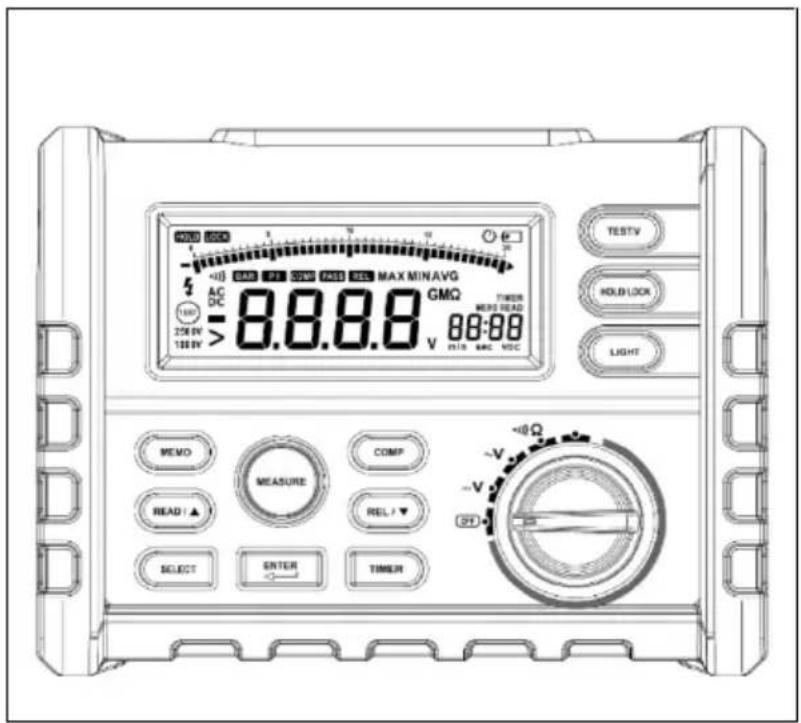
text_image
1000 1000 AC DC 250kV 100kV 8.8.8.8 GMΩ TIMER MINT READ 88:88 V RTR MAC NDC TESTV HOLDLOCK LIGHT MEMO MEASURE COMP READ / ▲ REL / ▼ SELECT ENTER TIMER +0Ω -V -0ΩTestboy® TV 431
Version 1.5
de Testboy® TV 431
Bedienungsanleitung
3
en Testboy® TV 431 21
Operating instructions
fr Testboy® TV 431
Manuel d'utilisation 39
es Testboy® TV 431 Manual de instrucciones 57
it Testboy® TV 431
Manuale dell'utente
75
nl Testboy® TV 431
Bedieningshandleiding 93
SV Testboy® TV 431 111
Bruksanvisning
fi Testboy® TV 431 129
Käyttöohje
Inhaltsverzeichnis
Hinweise 5
text_image
Technical diagram of a device control panel with labeled components in Chinesetext_image
0000_v n000Löschen von Daten
PI (Polarisationsindex) =
General safety notes 23
Safety 26
Instrument description 27
Fore side 27
Display 27
Display of messages 29
Buttons on the device 30
Rotary switch 30
Connection sockets 31
Functional description 31
Special functions 31
Automatic shut-down 31
Data hold function 31
Relative measurement 31
Locking the Test button for the insulation test 32
Saving measurement data 32
Displaying measurement data 32
Deleting data 32
Comparison function 33
Time function 33
The highest, lowest and average value 34
Differential Absorption Ratio (DAR) and polarization index (PI) 34
Basis measurements 35
DC voltage measurement 35
AC measurement 35
Resistance and continuity measurement 35
Insulation test 36
Replacing the battery 36
Specifications 37
Measurement accuracy 38
Information
Safety information

WARNING
Sources of danger are, for example, mechanical parts, which may cause serious personal injury.
Objects are also at risk (e.g. damage to the instrument).
WARNING
An electric shock can result in death or serious personal injury and endanger the function of objects (e.g. damage to the instrument).
WARNING
Never point the laser beam / LED beam towards the eyes either directly or indirectly via reflective surfaces. Laser radiation can cause irreparable damage to the eyes.
General safety notes

WARNING
Unauthorised modification and / or changes to the instrument are not permitted, for reasons of safety and approval (CE). In order to ensure safe and reliable operation of the instrument, you must always comply with the specifications of the safety instructions, warnings and the section "Intended use".

WARNING
Comply with the following specifications before using the instrument:
Do not operate the instrument anywhere near electric welding equipment, induction heaters or other electromagnetic fields.
After abrupt temperature fluctuations, the instrument must be allowed to adjust to the new ambient temperature for approx. 30 minutes before using it, in order to stabilise the IR sensor.
Do not expose the instrument to high temperatures for a long period of time.
Avoid dusty and humid environments.
Measuring instruments and their accessories are not toys, and must be kept out of the reach of children!
When working in industrial facilities, comply at all times with the specifications of the accident prevention regulations for electrical systems and equipment as established by the employer's liability insurance association.

Comply with the five safety rules:
1 Disconnect
2 Ensure that the instrument cannot be switched back on again
3 Ensure isolation from the power supply (both poles de-energized)
4 Earth and short-circuit
5 Cover adjacent live parts
Intended use
The instrument is intended strictly for use in applications described in the operating instructions. Any other usage is forbidden, and may result in accidents or destruction of the instrument. Any such usage will result in the immediate expiry of all guarantee and warranty claims on the part of the operator against the manufacturer.

Remove the batteries if the instrument is not in use for a long period of time, in order to protect the instrument from damage.

We assume no liability for damage to property or personal injury resulting from improper handling or non-compliance with the safety instructions. Any warranty claim expires in such cases. An exclamation mark in a triangle indicates safety instructions in the operating instructions. Read the instructions through before beginning initial commissioning. This instrument is CE-approved and thus fulfils the required guidelines.
We reserve the right to change specifications without prior notice © 2016 Testboy GmbH, Germany.
Disclaimer

The warranty claim expires in cases of damage caused by failure to comply with the instructions! We assume no liability for any resulting damage!
Testboy is not responsible for damage resulting from
Failure to comply with the instructions
Changes to the product that have not been approved by Testboy
The use of spare parts that have not been manufactured or approved by Testboy
The use of alcohol, drugs or medication.
Accuracy of the operating instructions
These operating instructions have been compiled with due care and attention. No guarantee is given that the data, illustrations and drawings are complete or correct. All rights reserved with regard to changes, printing mistakes and errors.
Disposal
Dear Testboy customer, purchasing our product gives you the option of returning the instrument to suitable collection points for waste electrical equipment at the end of its lifespan.

The WEEE directive regulates the return and recycling of electrical appliances.
Manufacturers of electrical appliances are obliged to take back and recycle all electrical appliances free of charge. Electrical devices may then no longer be disposed of through conventional waste disposal channels. Electrical appliances must be recycled and disposed of separately. All equipment subject to this directive is marked with this logo.
Disposal of used batteries

As an end user, you are legally obliged (battery law) to return all used batteries; disposal in the normal domestic waste is prohibited!
Batteries containing contaminant material are labelled with this symbol indicating that they may not be disposed of in normal domestic waste.
The abbreviations used for the crucial heavy metals are:
Cd = cadmium, Hg = mercury, Pb = lead.
You can return your used batteries to collection points in your community or anywhere where batteries are sold free-of-charge.
Certificate of quality
All activities and processes carried out within Testboy GmbH relating to quality are subject to ongoing monitoring within the framework of a Quality Management System. Furthermore, Testboy GmbH confirms that the testing equipment and instruments used during the calibration process are subject to an ongoing inspection process.
Declaration of conformity
The product conforms to the most recent directives. For more information, go to www.testboy.de
Safety
The insulation tester was developed and manufactured in accordance with the requirements of the safety standard for electronic test instruments. The specifications for category III 1,000 V and pollution degree 2 were maintained entirely.
Warning
Comply with the following instructions to avoid an electric shock or injury.
- Only use the test instrument in accordance with the specifications of these instructions, otherwise it is not possible to ensure safe operation of the instrument.
- Do not use the test instrument or the test leads if they present visible damage or if the device does not function correctly. If in doubt, send the unit for maintenance.
- Before connecting the test instrument to the circuit to be tested, always ensure that the correct connection, switch position and measurement range is used.
- Check the function of the test instrument by measuring a known voltage.
- Do not apply a voltage between the connections or between the connection and ground which is higher than the nominal voltage stated on the test instrument.
Exercise especial caution with voltages of over 30 V AC effective voltage, 42 V AC peak voltage or 60 V DC voltage, as these voltage values could result in an electric shock. - Replace the batteries as soon as a low charge status is displayed.
- Disconnect the power supply and discharge all high-voltage capacitors before measuring the resistance, continuity or capacity.
● Never use the test instrument in proximity to explosive gases or steams.
● When using the test leads, ensure that you keep your fingers behind the finger protector. - Remove the test leads from the test instrument before opening the housing or the battery compartment of the test instrument.
● Never commission the device unless the protective cover is in position or if the battery compartment is open.
● Comply with the local and national safety specifications when working in hazardous environments. - Wear the correct protective equipment as specified in local and national regulations when working in hazardous environments.
- Use only the specified replacement fuses; failure to do so will mean that the protection of the device is not guaranteed.
Instrument description
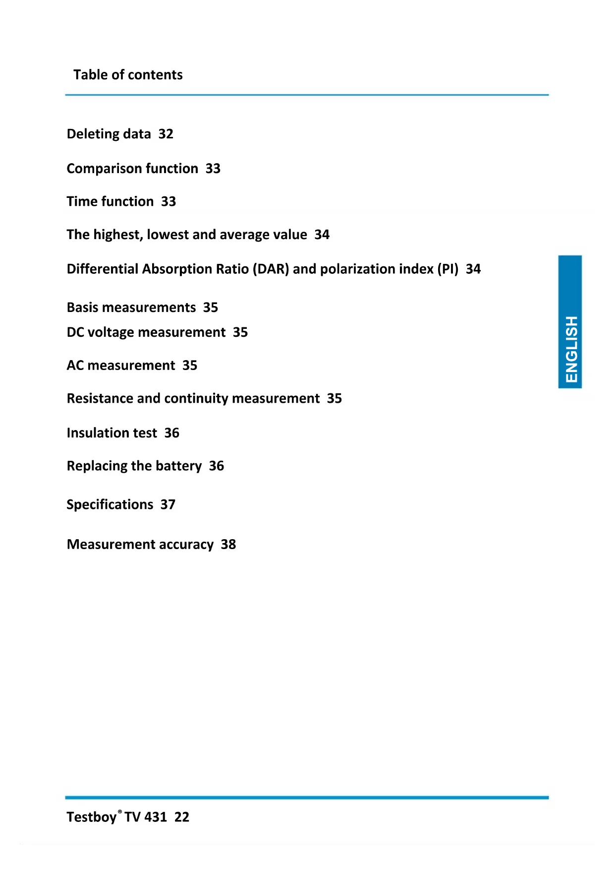
Fore side
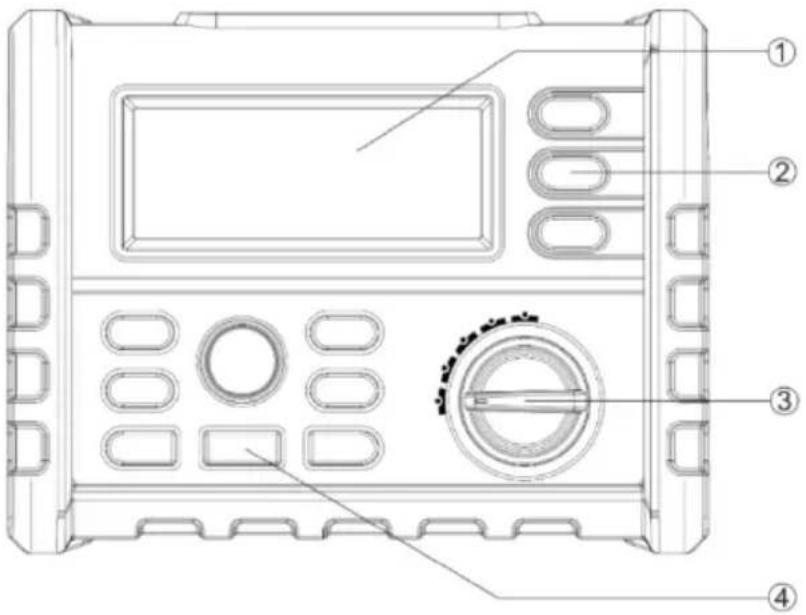
text_image
Technical diagram of a device control panel with labeled components in Chinese| Buttons | Description |
| 1 | Display |
| 2 | Button |
| 3 | Rotary switch |
| 4 | Enter button |
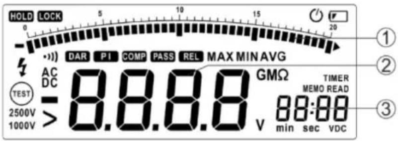
Display
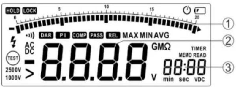
text_image
HOLD LOCK 0 - ) DAR PI COMP PASS REL MAX MIN AVG AC DC TEST 2500V > 8.8.8.8 GMΩ TIMER 1000V 88:00 V min sec VDC| Buttons | Description |
| 1 | Bar graph display |
| 2 | Data display |
| 3 | Memory |
| Element on the display | Description |
| Display of a low battery status. Replace the battery given a low charging status.To avoid incorrect measuring results, which could lead to an electric shock or injury,replace the battery immediately when this is registered on the display. | |
| LOCK | Indicates that the button will be locked during the next depression of the Test button onthe test instrument, i.e. It will remain activated until you have pressed the Test buttonagain. |
| HOLD | Hold function; the display is not updated. |
| COMP | The comparison function was selected. |
| PASS | This display is shown if the comparison function has been activated and the measuredvalue is located in the permissible range between the upper and lower limit value. |
| DAR | The comparison function was selected. |
| REL | Display of the differential absorption ration (DAR) in the insulation test mode. |
| PI | Display of the polarization index (PI) in insulation test mode. |
| TIMER | The time function was selected. |
| MEMO | The memory function was selected. |
| READ | Display of the saved data, invalid data is displayed with --- |
| DC | The DC voltage function was selected. |
| AC | The AC voltage function was selected. |
| VDC | The test voltage unit is checked in the insulation test mode. |
| Minus sign; is displayed if the measured value lies under 0. | |
| > | Larger than; indicates in insulation test mode that the measured value is too high. |
| Warning against dangerous voltage; in insulation test mode shows that a voltage ofover 20 V has been registered at the input connections. | |
| 011) | Continuity test was selected. |
| Automatic shut-down was selected. | |
 | Display of the insulation test. If the rotary switch is set to “INSULATION” (insulation test mode) this sign will be displayed if the test voltage is applied; the sign will be displayed or suppressed. |
| 2500V1000V | Nominal source voltage for the insulation test. |
| min sec | Measurement units time function. |
 | Measurement unit measuring result. |
| MAX MIN | Display of the highest, lowest and average value. |
Display of messages
| Message | Description |
| batt | Displayed on the main display; means that the battery is not sufficiently charged for reliable operation. Replace the battery. |
| bat | Displayed on the auxiliary display; means that the battery is not sufficiently charged for an insulation test. |
| P r E S | Pre-set value. |
| POFF | Automatic deactivation was switched off. |
| LIVE | In insulation test mode, indicates that the unit has registered the voltage on the input connections. |
| DISC | In insulation test mode, indicates that the unit is performing an automatic discharge. Do not touch any of the input connections in this mode. |
| SAVE | Measured data are saved. |
| dEL n: | The selected data will be deleted. |
| dEL ALL | All saved data is deleted. |
| COMP Hi | Upper limit value. |
| COMP Lo | Lower limit value. |
| ---- COMP | Limit value invalid. |
| •••)OFF | Acoustic signal output deactivated. |
Buttons on the device
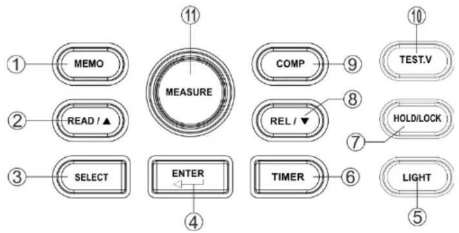
text_image
1 MEMO 2 READ / ▲ 3 SELECT 4 ENTER 5 11 MEASURE COMP 8 REL / ▼ 6 TIMER 7 TEST.V 10 HOLD/LOCK LIGHT| Buttons | Description |
| 1 | Activates the memory function: The measurement data is transferred to the memory. |
| 2 | Activates the display function; changes the position of the cursor to display the saved files. |
| 3 | 1: in DC-V-, AC-V- and continuity mode, display of the highest, lowest and average value, the upper and lower limit values, and the relative value2: in insulation test mode, display of the highest, lowest and average value, the upper and lower limit values, the pre-set time function, the differential absorption ratio and the polarisation index. |
| 4 | Enter button for confirmation. |
| 5 | Switches the background illumination on or off; if activated, the background illumination switches itself off automatically after 10 s. |
| 6 | Activates the time function. |
| 7 | Activates the data hold function (DC-V-, AC-V-, continuity mode) or the locking function (insulation test mode). |
| 8 | Activates the relation function (DC-V-, AC-V-, continuity mode); change the cursor position. |
| 9 | Activates the comparison function. |
| 10 | Selects a test output voltage for the insulation test |
| 11 | Activates the insulation test |
Rotary switch
| Position | Function |
| OFF | Switches off the instrument |
| V | DC voltage: 0.1 V – 1000 V |
| V | AC voltage 0.1 V – 750 V |
| 1)) | Resistance and continuity 0.01 Ω – 200.0 Ω |
| Insulation | Insulation test 0.01 MΩ – 100.0 GΩ, test output voltage 250 V (factory setting), 500 V, 1000 V, 2500 V, the test output voltage selected is saved. |
Connection sockets
| Connection | Description |
| HI √Ω | Input / output positive connection |
| COM | Negative connection for all measurements (except insulation measurement) |
| LO | Negative connection for insulation measurement |
Functional description
Special functions
Additional functions are available during device activation. To select the respective special function, depress the corresponding button depressed and turn the rotary switch from OFF to a different position. The special function is deactivated when then device is switched off (OFF).
| Buttons | Function |
| SELECT | Automatic deactivation is deactivated. The display shows PoFF until the button is released. |
| ENTER | The acoustic signal issue is deactivated. |
Automatic shut-down
The test instrument is fitted with an automatic deactivation function (sleep mode) to protect the battery. This triggers if no function has been actuated for 10 minutes and no button has been pressed. The sleep mode ends as soon as a button has been pressed or a rotary switch is adjusted.
If you wish to end sleep mode, hold and depress the SELECT button whilst you activate the test instrument. Sleep mode is deactivated in insulation test mode as a matter of course or if the automatic deactivation has been deactivated by pressing the SELECT button after the device has been activated.
Data hold function
Press the HOLD button to hold on to the displayed value. Pressing the button again means that the value is no longer held.
Relative measurement
The relative measurement displays the difference between the actual value and the relative base value.
Press the REL button to perform a relative measurement; the device detects the initial value when the button is pressed.
Displayed value = actual value - initial value
To end the relative measurement, press the REL button again.
You can display the initial value using the SELECT button. If this is invalid, the display will show ---

text_image
100.0 REL v PrESLocking the Test button for the insulation test
Press the Test button in insulation test mode to perform the insulation test until the button has been released. The display will show the HOLD symbol as soon as the button has been released.
Press the LOCK button (the display will show LOCK) and then the Test button. An insulation test will be performed until you press the Test button again. The Test button is unlocked and the insulation test aborted.
If the time function has been activated, the function for locking the Test button is not available.
Saving measurement data
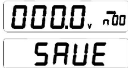
Pressing the MEMO button activates the data hold function automatically. 'MEMO' appears on the LC display and; the auxiliary display shows the memory cell (see below). Change the code with the / buttons and save the data with the ENTER button in the desired memory cell. The display shows 'SAVE' If a signal tone is issued, the data has been saved. The device can save 20 data entries and memory cell between 00 and 19.
text_image
000.0_v → SAVEDisplaying measurement data
Press the READ button to display the saved data. Use the / buttons to select the desired code and access the appendant data.

text_image
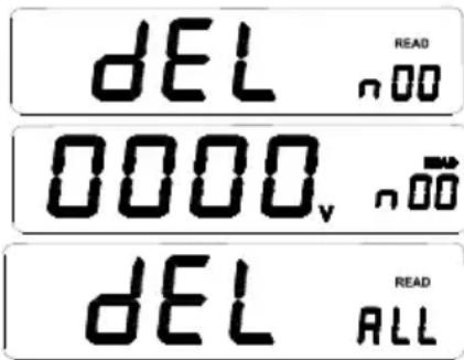
0000_v n00Deleting data
Working in READ mode, press the ENTER button. The display shows dEL n. Press the ENTER button again to delete the selected data. You can delete all the data using the READ button. A signal tone indicates that the data has been deleted. Press a different button to leave the current mode.
text_image
DEL READ n 00 0000v n 00 dEL READ ALLComparison function
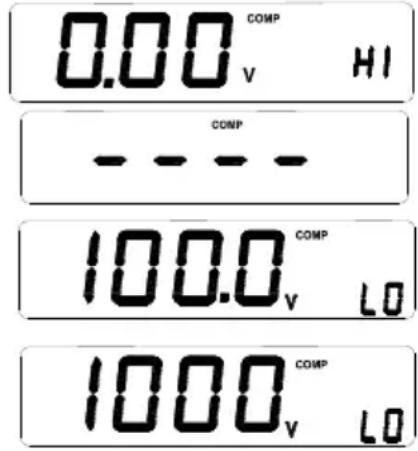
If the comparison function has been activated and the measured value exceeds or undercuts the upper or lower limit value, a signal tone sounds and the text 'PASS' is not shown on the display.
The comparison function can be activated with 'COMP'; the display shows 'COMP'. If the pre-set upper limit value is smaller than the lower limit value, the comparison function is invalid; '-' is displayed.
Press the COMP button to show the upper and lower limit values. The display shows 'COMP' and the auxiliary display shows either 'HI' or 'LO' (see below): If the upper or lower limit value is shown on the display, you can change the value by pressing the ENTER button. The limit value displayed begins to flash. Use the SELECT button to select the correct measurement range. Set the desired value with the / buttons and save the setting with ENTER.
text_image
0.00 COMP v HI COMP 100.0 COMP v LO 1000 COMP v LOTime function
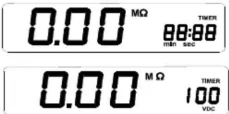
The time function is only available during the insulation test. Press the TIMER button to activate the time function (the display shows TIMER). The function with which to lock the Test button is not available when the time function has been activated. The insulation test is performed as soon as the MEASURE button has been actuated. The test comes to an end after a pre-set time frame.
The following display is shown in the time function mode. The current voltage and the time are shown on the auxiliary display. The test voltage is displayed whilst an insulation test is being carried out. Press the button to display the time.
text_image
0.00 MΩ 88:88 min sec 0.00 MΩ 100 VDC TIMERPress the SELECT button to view the pre-set time frame. The LC display shows TIMER. The main display shows PRES; the auxiliary display shows the pre-set time frame. Press ENTER. The display shows 'Set'. You can set the time-frame with the △/▽ buttons. Press ENTER again to accept this setting.
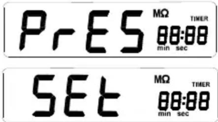
text_image
PRES MΩ 00:00 min sec SET MΩ 00:00 min sec TIMERThe highest, lowest and average value
When working in test mode, you can display the highest, lowest and average value using the SELECT button. When working in data hold mode, you can display the values with the SELECT button.
Differential Absorption Ratio (DAR) and polarization index (PI)
There are cases in which no further intact isolation parts (which e.g. have lost their isolating effect under high voltage) but which still present a good absorption ratio (or a good polarization index). The absorption ratio (polarization index) can only be used to ascertain local isolation damage; they offer no indication as to dampness and contamination.
$$ \begin{array}{l l} \text {DAR (absorption ratio) =} & \frac {R 6 0 S e c}{R 1 5 S e c} \ \text {PI (polarization index) =} & \frac {R 1 0 M i n}{R 1 M i n} \end{array} $$
R10Min= resistance value measured 10 minutes after applying the test voltage; R1Min=R60Sec= resistance value measured 1 minute after applying the test voltage; R15Sec= resistance value measured 15 seconds after applying the test voltage
After completing the insulation test, press the SELECT button to display the DAR and PI values. Should the DAR and PI values be invalid, the display will show - - - .
Basis measurements
DC voltage measurement
Move the rotary switch to -V. Connect the input connections and test leads as shown here and connect the test leads to the voltage source / consumer.
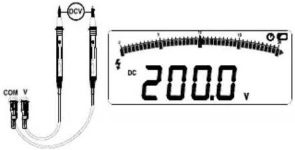
text_image
DCV COM V DC 200.0 vAC measurement
Move the rotary switch to 📋 Connect the input connections and test leads as shown here and connect the test leads to the voltage source / consumer.
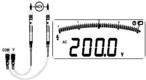
text_image
ACV COM V 4 AC 200.0 VResistance and continuity measurement
To avoid any damage to the test instrument or the system to be tested, disconnect the circuit power supply and discharge all the high-voltage capacitors before performing a continuity test.
Move the rotary switch to ) . Connect the test leads as shown. A signal will sound during the continuity test with a measured resistance of < 3 .

text_image
COM V 200.0°Insulation test
Warning: To avoid damaging the test voltage, do not adjust the rotary switch when outputting the test voltage.
● Insulation tests may only be performed on circuits free of voltage. Check the test leads before performing the insulation test.
- Move the rotary switch to INSULATION. If the display shows ☐, replace the batteries.
- Connect the test leads to the connections High and Low. If the display shows 'Live' this means that a measurement cannot be performed, as the circuit is live. Switch the circuit voltage-free.
- Select the output voltage with the TEST.V button.
- The TEST symbol will flash during the insulation test. The main display will show the resistance value and the auxiliary display will show the output voltage. Release the Test button. The discharge procedure is performed via the test instrument; the display will show DISC
● The auxiliary display indicates when the discharge procedure has been completed (0 VDC).
● Disconnect the test leads from the circuit.

text_image
LOW HI 520 MΩ 520 VDC TEST 500V >Replacing the battery
To avoid incorrect measuring results, which could lead to an electric shock or injury, replace the battery immediately when the display shows .
Turn the rotary switch to OFF and disconnect the test leads from the connections.
Unscrew and remove the cover of the battery compartment.
Replace the batteries whilst complying with the polarity.
Replace the cover of the battery compartment and screw down.
Specifications
Corresponds to the requirements of IEC/EN 61010-1 CAT III 1000 V / CAT IV 600 V
1000 V DC voltage, 750 V AC voltage
The overload protection voltage between the input connections Hi and Lo amounts to 600 V.
The overload protection voltage between the input connections V and COM amounts to 1200 V during the voltage test in and 250 V in other test modes.
| Batteries: | 6 C batteries (baby or LR14) operating duration of the test instrument 1000 hours; performing insulation tests: The device is designed for min. 1000 insulation tests with new alkali batteries at room temperature. These are standard tests with 1000 V at 1 MΩ with a load cycle of 5 seconds on and 25 seconds off. |
| Insulation measurement range: | 0.01 MΩ to 100.0 GΩ. |
| Insulation test voltages: | 250, 500, 1000, 2500 V . |
| Insulation source voltage: | + 20 %, - 0 %. |
| Insulation short-circuit test current: | 3.0 mA nominal. |
| Detection of a live circuit before the insulation test: No test is performed if the connection voltage amounts to > 20 V before the start of the test. | |
| Maximum capacitative load of the insulation. | Functional up to 1 μF. |
| Storage temperature: | -40 °C to 60 °C. |
| Operating temperature: | 0 °C to 40 °C. |
| Storage altitude: | 12000 m |
| Operating altitude: | 2000 m 1000 V CAT. III, 3000 m 1000 V II |
| Temperature coefficient: | 0,05 × (specified exactness) per °C at temperatures from < 18 °C or > 28 °C. |
| Relative air humidity: | 40 % – 75 % (40 % – 60 %, if the insulation test produces > 1 GΩ) |
| Size: | 180 mm (L) × 140 mm (W) × 65 mm (H). |
| Weight: | approx. 900 g (without battery) |
Measurement accuracy
DC-V
| RANGE | MEASUREMENT ACCURACY IN V | MEASUREMENT ACCURACY IN Ω |
| 200 V | 0.1 V | ± 0.5 % Meas. value + 5 digits |
| 1000 V | 1 V | ± 0.5 % Meas. value + 5 digits |
AC-V
| RANGE | MEASUREMENT ACCURACY IN V | MEASUREMENT ACCURACY IN % (50 – 60 Hz) |
| 200 V | 0.1 V | ± 1.5 % Meas. value + 5 digits |
| 750 V | 1 V | ± 1.5 % Meas. value + 5 digits |
Resistance
| RANGE | MEASUREMENT ACCURACY IN Ω | MEASUREMENT ACCURACY IN Ω |
| 20 Ω | 0.01 Ω | ± 1 % Meas. value + 5 digits |
| 200 Ω | 0.1 Ω | ± 1 % Meas. value + 5 digits |
Insulation test
| OUTPUT VOLTAGE | RANGE | MEASUREMENT ACCURACY IN Ω | MEASUREMENT ACCURACY IN % |
| 250 V (0 – 20 %) | 0 – 20 MΩ | 0.01 MΩ | ± 3 % meas. value + 5 digit |
| 20 MΩ – 200 MΩ | 0.1 MΩ | ||
| 200 MΩ – 250 MΩ | 1 MΩ | ||
| 500 V (0 – 20 %) | 0 – 20 MΩ | 0.01 MΩ | ± 3 % meas. value + 5 digit |
| 20 MΩ – 200 MΩ | 0.1 MΩ | ||
| 200 MΩ – 500 MΩ | 1 MΩ | ||
| 1000 V (0 – 20 %) | 0 – 20 MΩ | 0.01 MΩ | ± 3 % meas value + 5 digit |
| 20 MΩ – 200 MΩ | 0.1 MΩ | ||
| 200 MΩ – 1000 MΩ | 1 MΩ | ||
| 2500 V (0 – 20 %) | 0 MΩ – 2000 MΩ | 1 MΩ | ± 3 % meas. value + 5 digit |
| 2000 MΩ – 20 GΩ | 0.01 GΩ | ± 5 % meas. value + 0.2 GΩ | |
| 20 GΩ – 100 GΩ | 0.1 GΩ | ± 10 % meas. value + 2 GΩ |
Table des matières
Consignes 41
Cd = Cadmium, Hg = mercure, Pb = plomb.
text_image
Technical diagram of a device control panel with labeled components in Chinesetext_image
0000_v n000text_image
Technical diagram of a device control panel with labeled components in Chinesetext_image
0000_v n000Borrado de datos
text_image
Technical diagram of a device control panel with labeled components in Chinesetext_image
0000_v n000Cd = cadmium, Hg = kwik, Pb = lood.
text_image
Technical diagram of a device control panel with labeled components in Chinesetext_image
0000_v n000Wissen van gegevens
text_image
LOW HI 520 MΩ 520 vdcBatterijen vervangen
Cd = kadmium, Hg = kvicksilver, Pb = bly.
text_image
Technical diagram of a device control panel with labeled components in Chinese| Knappar | Beskrivning |
| 1 | Display |
| 2 | Knapp |
| 3 | Vridbrytare |
| 4 | Enter-knapp |
Display
text_image
HOLD LOCK 0 5 10 15 20 ① ② ③ DAR PI COMP PASS REL MAX MIN AVG AC DC TEST 2500V >8.8.8.8 GMΩ TIMER 1000V V min sec VDCtext_image
0000_v n000Ta bort data
Cd = Kadmium, Hg = Elohopea, Pb = Lyijy.
text_image
Technical diagram of a device control panel with labeled components in Chinesetext_image
0000_v n000text_image
Testboy® GmbH, Germany Stands For Quality Since 1953Testboy GmbH Tel: +49 4441 / 89112-10
Germany info@testboy.de