MasterCross-Laser XPG - Laser level Laserliner - Free user manual and instructions
Find the device manual for free MasterCross-Laser XPG Laserliner in PDF.
User questions about MasterCross-Laser XPG Laserliner
0 question about this device. Answer the ones you know or ask your own.
Ask a new question about this device
Download the instructions for your Laser level in PDF format for free! Find your manual MasterCross-Laser XPG - Laserliner and take your electronic device back in hand. On this page are published all the documents necessary for the use of your device. MasterCross-Laser XPG by Laserliner.
USER MANUAL MasterCross-Laser XPG Laserliner
natural_image
Exterior view of a Laserliner device (no visible text or symbols on body)
Laser
515nm
AUTOMATIC
LEVEL

GRX READY

lock

erGreen +
LASER
ADS
Tilt
natural_image
3D wireframe diagram of a cube with internal lines and shading (no text or symbols)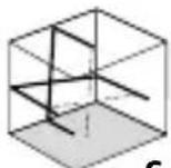
Laserliner
DE
02
EN
12
NL
22
DA
32
FR
42
ES
52
IT
62
PL
FI
PT
SV
NO
TR
RU
UK
CS
ET
RO
BG
EL
HR
!
natural_image
Isometric diagram of a cube with internal lines and shading (no text or symbols)1H 1V S

4-Punkt-Laser
natural_image
Technical line drawing of a mechanical device with no visible text or symbolsnatural_image
Close-up of a mechanical device with a black arrow pointing to a component (no visible text or symbols)!
!
!
Completely read through the operating instructions, the „Warranty and Additional Information” booklet as well as the latest information under the internet link at the end of these instructions. Follow the instructions they contain. This document must be kept in a safe place and if the laser device is passed on, this document must be passed on with it.
Intended use
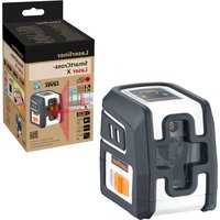
This cross-line laser is for aligning horizontals, verticals and slopes It projects a green laser cross and four plumb points which are suitable for transferring marks between floors and ceilings as well as wall to wall. Optical signals indicate when the laser is outside its self-levelling range. The laser has an integrated hand-held receiver mode for the following receivers: G 60, G 30 and M50 RangeXtenders and the CombiRangeXtender 40. It can be combined with tripods with a 1/4" or 5/8" thread.
General safety instructions
- The device must only be used in accordance with its intended purpose and within the scope of the specifications.
- The measuring tools and accessories are not toys. Keep out of reach of children.
- Modifications or changes to the device are not permitted, this will otherwise invalidate the approval and safety specifications.
- Do not expose the device to mechanical stress, extreme temperatures, moisture or significant vibration.
- The device must no longer be used if one or more of its functions fail or the battery charge is weak.
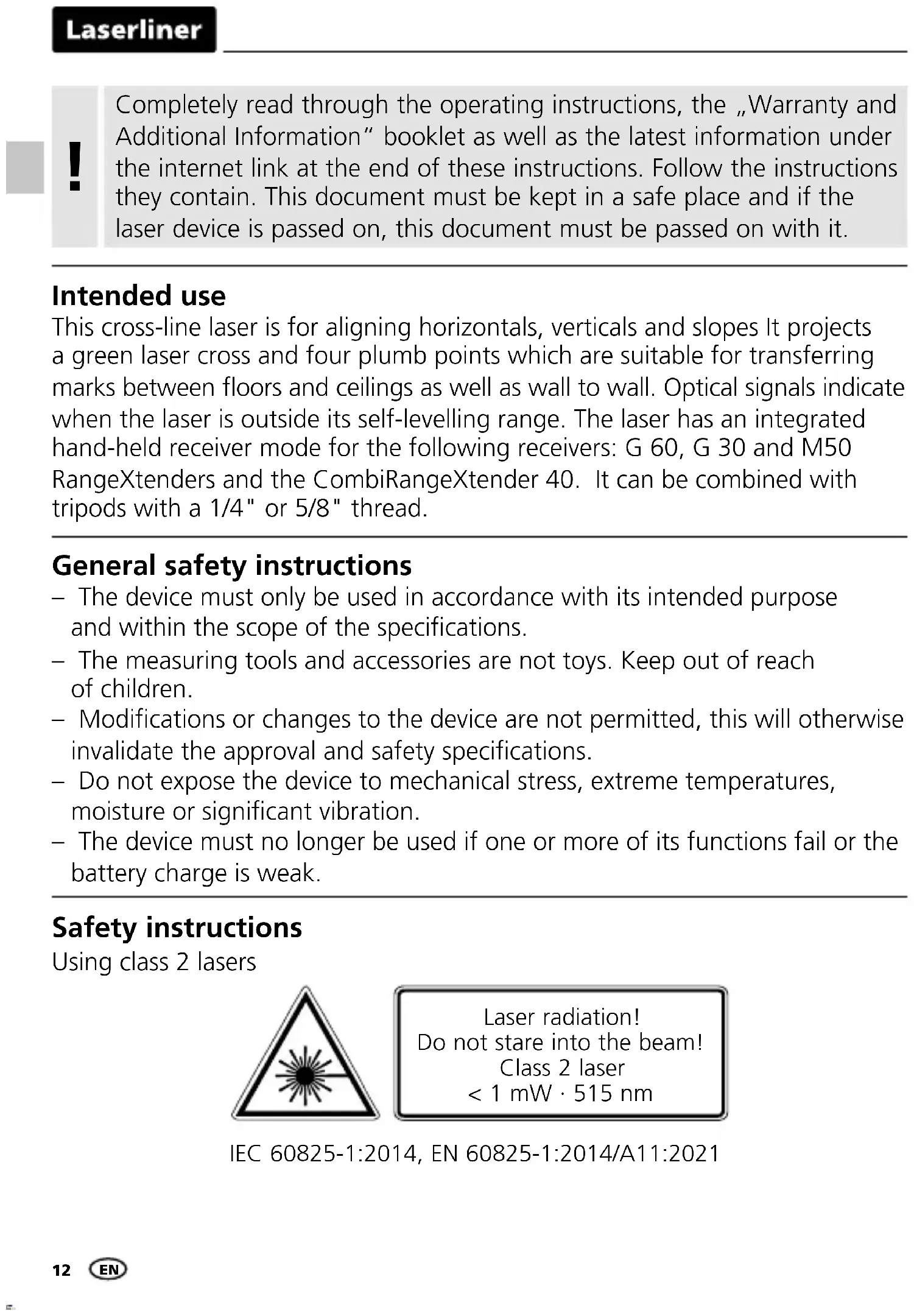
Safety instructions
Using class 2 lasers
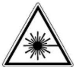
Laser radiation! Do not stare into the beam! Class 2 laser < 1 mW · 515 nm
IEC 60825-1:2014, EN 60825-1:2014/A11:2021
- Attention: Do not look into the direct or reflected beam.
- Do not point the laser beam towards persons.
- If a person's eyes are exposed to class 2 laser radiation, they should shut their eyes and immediately move away from the beam.
- Under no circumstances should optical instruments (magnifying glass, microscope, binoculars) be used to look at the laser beam or reflections.
- Do not use the laser at eye level (1.40 ... 1.90 m)
- Reflective, specular or shiny surfaces must be covered whilst laser devices are in operation.
- In public areas shield off the laser beam with barriers and partitions wherever possible and identify the laser area with warning signs.
Safety instructions
Dealing with electromagnetic radiation
- The measuring device complies with electromagnetic compatibility regulations and limits in accordance with the EMC Directive 2014/30/EU.
- Local operating restrictions – for example, in hospitals, aircraft, petrol stations or in the vicinity of people with pacemakers – may apply. Electronic devices can potentially cause hazards or interference or be subject to hazards or interference.
- The measuring accuracy may be affected when working close to high voltages or high electromagnetic alternating fields.
Special product features

Automatic alignment of the device with a magnetically dampened pendulum system. The device is brought into initial position and aligns itself autonomously.

Transport LOCK: The device is protected with a pendelum lock during transport.

GRX-READY technology enables line lasers to be used even in unfavourable light conditions. The laser lines pulsate at a high frequency and this can be picked up by special laser receivers over long distances.

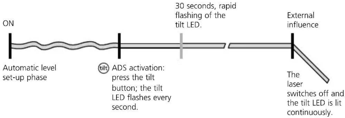
The anti-drift system (ADS) prevents erroneous or inaccurate measurements. How it works: continuous monitoring of the alignment of the laser is activated 30 seconds after the ADS is switched on. If the device moves due to external influences or if the laser loses its height reference, the laser switches off and the tilt LED lights up permanently. Press the tilt button to continue. Erroneous and inaccurate measurements are thus prevented simply and reliably.

The ADS is not active following switch-on. Once the device has been set up, press the tilt button to activate the ADS, enabling you to protect the laser from changes in position caused by the device being disturbed by external factors. The tilt LED flashes to indicate that the ADS function is active; see the diagram below.

The ADS does not activate the monitoring function until 30 seconds after the laser levelling procedure has been completed (set-up phase). The tilt LED flashes every second during the set-up phase, rapid flashing, when ADS is active.
ADS function
flowchart
graph LR
    A["ON"] --> B["Automatic level set-up phase"]
    B --> C["30 seconds, rapid flashing of the tilt LED."]
    C --> D["External influence"]
    D --> E["Laser switches off and tilt LED is lit continuously."]
    F["ADS activation: press the tilt button; the tilt LED flashes every second."] --> B
Green laser technology
Approx. 6 times brighter than a typical red laser with 630 - 660 nm.

Devices with the PowerGreen+ technology have very bright, green high-performance diodes which provide outstanding visibility of the laser lines at great distances, on dark surfaces and in bright ambient lighting conditions.
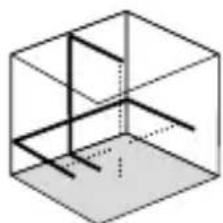
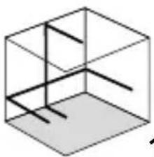
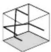
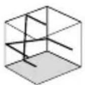
Number and direction of the lasers
Cross-line laser
H = horizontal laser
V = vertical laser
S = slope function
natural_image
Isometric diagram of a cube with internal lines and shading (no text or symbols)1H 1V S
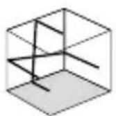
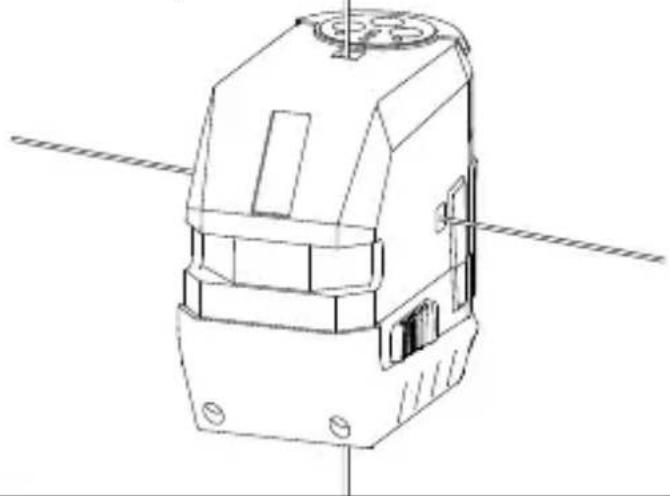
4-point laser

natural_image
Technical line drawing of a mechanical device with no visible text or symbols1 Use of lithium-ion rechargeable battery
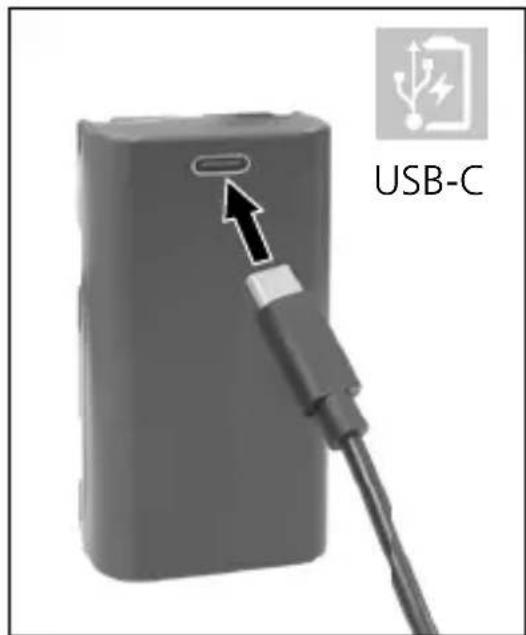
- Use the power supply/charger unit only in closed rooms; do not expose to moisture or rain otherwise risk of electric shock.
- Charge the device's battery completely prior to use.
- Connect the power pack/charger to the mains power supply and the socket in the battery pack. Please only use the power pack/charger supplied. Using any other power pack/charger will invalidate the warranty.
- The LED on the battery pack lights up red while the battery is charging. When the LED changes to blue, charging is complete.
Laserliner
!
The battery may only be charged with the battery charger provided and used only in this laser device. Any other use may cause injury or fire.
!
Make sure there are no conductive objects in the vicinity of the battery contacts. Short-circuiting of these contacts can cause burn injuries or fire.
!
Do not open the rechargeable battery. This could cause short-circuits.
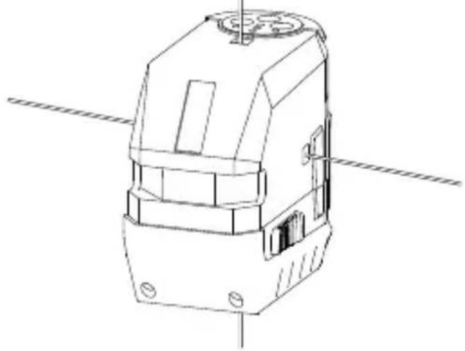
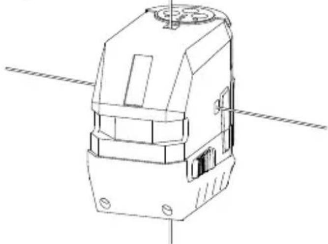
1
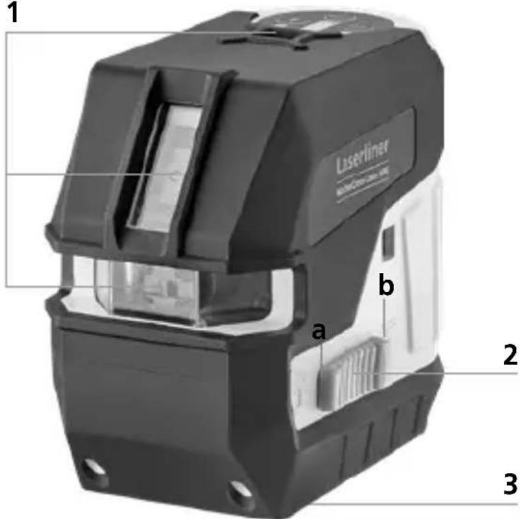
1 Laser output windows
2 Slide switch
a ON
b OFF / Transport lock / Slope mode
3 1/4" / 5/8" tripod threads (bottom)
4 Battery status
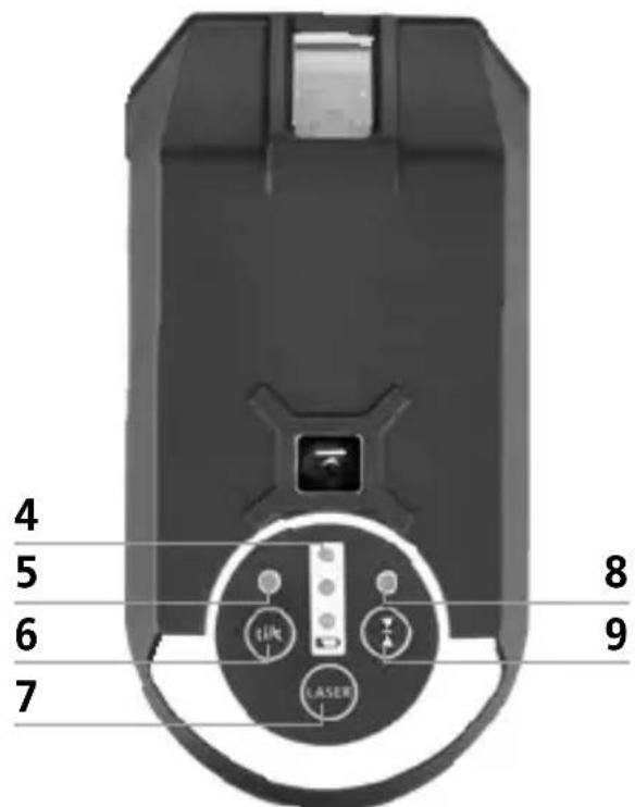
5 LED levelling
6 Tilt function
7 Laser line selection button; levelling on / off
8 LED hand receiver mode
9 Hand receiver mode on / off
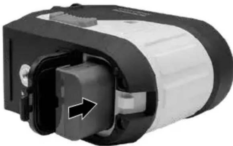
2 Power supply To insert the lithium-ion rechargeable battery
Open the battery compartment and insert the lithium-ion battery as illustrated.
natural_image
Close-up of a mechanical device with a black and white housing and a directional arrow indicating flow or movement (no visible text or symbols)When transporting, always switch off all lasers, secure pendulum and push the slide switch (2) to the right.
3 Horizontal and vertical levelling
Release the transport restraint, push the slide switch (2) to the left. The laser cross will appear. The laser lines can be switched individually with the selection button.
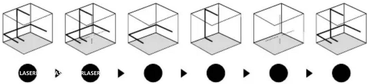
flowchart
graph LR
    A["LASER"] --> B["AS"]
    B --> C["RLASER"]
    C --> D["●"]
    D --> E["●"]
    E --> F["●"]
    F --> G["●"]
! levelling. The laser lines flash as soon as the device is outside the automatic levelling range of 3.5°. Position the device such that it is within the levelling range. The laser lines stop flashing (steady light).
4 Slope mode
Do not release transport restraint, push slide switch (2) to the right.
Switch on the lasers by holding down the selection button (7).
Press it again to set the selection. Sloping planes and tilts can now be measured. In this mode, the laser lines will no longer align automatically, which will be indicated by the laser lines switching off briefly, roughly every five seconds.
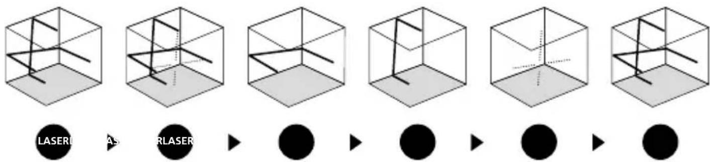
flowchart
graph LR
    A["3D Cube with diagonal lines"] --> B["3D Cube with vertical lines"]
    B --> C["3D Cube with circular nodes"]
    C --> D["2D Circle with solid black dots"]
    D --> E["2D Circle with solid black dots"]

The device can be switched off in any laser selection by holding down the button (7).
5 Hand receiver mode
Optional: Working with the laser receiver GRX
Use an laser receiver (optional) to carry out levelling at great distances or when the laser lines are no longer visible. To work with a laser receiver, switch the line laser to hand-held receiver mode by pressing button 9 (handheld receiver mode on / off). The laser lines will now pulsate with high frequency, making the laser lines darker. The laser receiver can detect these pulsating laser lines.
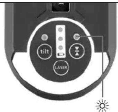

Observe the laser receiver's operating instructions for line lasers.
Preparing the calibration check
It is possible for you to check the calibration of the laser. To do this, position the device midway between 2 walls, which must be at least 5 m apart. Switch the device on (Laser cross ON). The best calibration results are achieved if the device is mounted on a tripod.
- Mark point A1 on the wall.
- Turn the device through 180^ and mark point A2. You now have a horizontal reference between points A1 and A2.
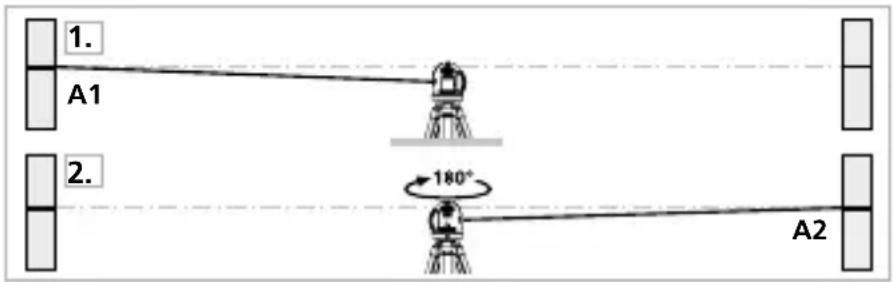
Performing the calibration check
- Position the device as near as possible to the wall at the height of point A1.
- Turn the device through 180^ and mark point A3. The difference between points A2 and A3 is the tolerance.
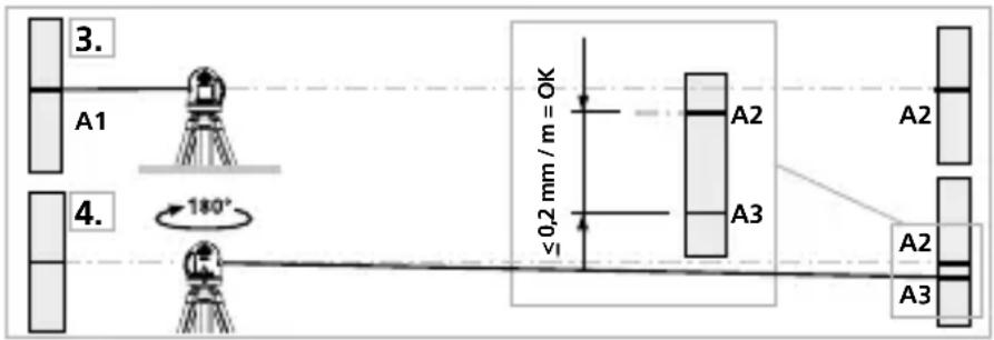
!
When A2 and A3 are more than 0.2 mm / m apart, an adjustment is necessary. Contact your authorised dealer or else the UMAREX-LASERLINER Service Department.
Checking the vertical line
Position the device about 5 m from a wall. Fix a plumb bob with a line of 2.5 m length on the wall, making sure that the bob can swing freely.
Switch on the device and align the vertical laser to the plumb line.
The precision is within the specified tolerance if the deviation between the laser line and the plumb line is not greater than ± 2 mm.
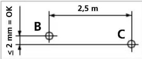
Checking the horizontal line
Position the device about 5 m from a wall and switch on the cross laser. Mark point B on the wall. Turn the laser cross approx. 2.5 m to the right and mark point C. Check whether the horizontal line
from point C is level with point B to within ± 2 mm. Repeat the process by turning the laser to the left.
!
Regularly check the calibration before use, after transport and after extended periods of storage.
Information on maintenance and care
Clean all components with a damp cloth and do not use cleaning agents, scouring agents and solvents. Remove the battery before storing for longer periods. Store the device in a clean and dry place.
Calibration
The meter needs to be calibrated and tested on a regular basis to ensure it produces accurate measurement results. We recommend carrying out calibration once a year. Contact your authorised dealer or else the UMAREX-LASERLINER Service Department.
| Technical data (Subject to technical changes without notice. 23W34) | |
| Self-levelling range | ± 2,5° (horizontal) |
| Accuracy ± 0,2 mm / m | |
| Levelling | automatic |
| Visibility (typical)* | 55 m |
| Working range with hand receiver | 60 m (von technisch bedingtem Helligkeitsunterschied abhängig) |
| Laser wavelength | 515 nm |
| Laser class | 2 / < 1 mW (IEC 60825-1:2014, EN 60825-1:2014/A11:2021) |
| Degree of protection | IP 64 |
| Power supply | Li-ion battery pack 7.4V / 2.6Ah / 19.24Wh Power pack 5V/DC / 2A |
| Tripod connection | 1/4" - / 5/8" thread |
| Operating time ca. 8 Std. | |
| Charging time approx. 4 hours | |
| Operating conditions | 0°C ... 50°C, max. humidity 80% rH,no condensation, max. working altitude 4000 m above sea level |
| Storage conditions -10°C ... 70°C, max. humidity 80% rH | |
| Dimensions (W x H x D) | 128 x 110 x 67 mm |
| Weight | 588 g (incl. battery pack) |
* at max. 300 lux
EU and UK directives and disposal
This device complies with all necessary standards for the free movement of goods within the EU and the UK.
This product, including accessories and packaging, is an electrical appliance that must be recycled in an environmentally appropriate manner in accordance with European and UK directives on waste electrical and electronic equipment, batteries and packaging, in order to recover valuable raw materials.
Further safety and supplementary notices at:
https://www.laserliner.com
!
natural_image
Isometric line drawing of a 3D cube with internal lines and shading (no text or symbols)1H 1V S
4-puntslaser
natural_image
Line drawing of a mechanical device with no visible text or symbolsnatural_image
Close-up of a mechanical device with a black and white housing and a directional arrow indicating flow or movement (no visible text or symbols)!
!
natural_image
Warning symbol with a sunburst pattern inside a triangle (no text or numbers)
natural_image
Isometric diagram of a cube with internal lines and shading (no text or symbols)1H 1V S

4-punkt-laser

natural_image
Technical line drawing of a mechanical device with no visible text or symbolsnatural_image
Close-up of a mechanical device with a black and white casing, showing internal components and a directional arrow (no text or symbols visible)natural_image
Warning symbol with a triangular triangle and central sunburst pattern (no text)natural_image
Isometric line drawing of a 3D cube with internal lines and shading (no text or symbols)1H 1V S
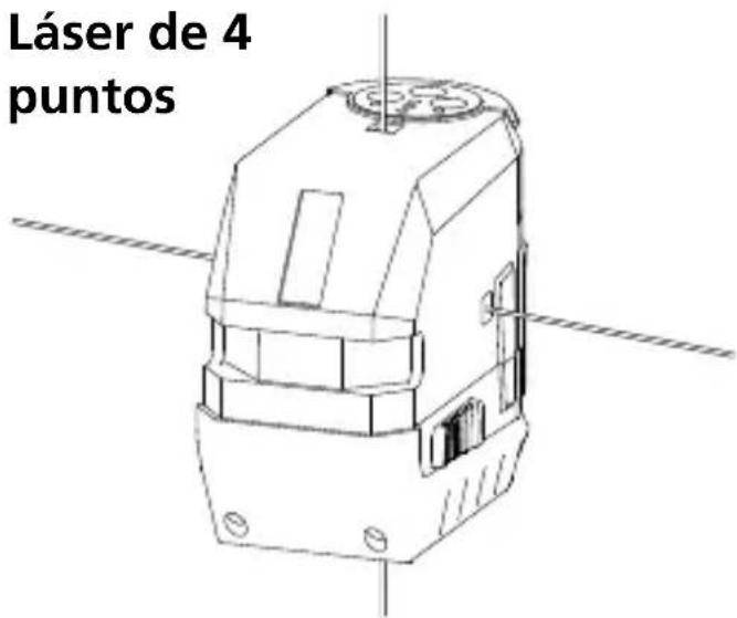
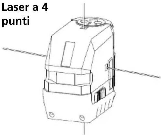
Laser 4 points
natural_image
Technical line drawing of a mechanical device with no visible text or symbolsnatural_image
Close-up of a mechanical device with a black and white casing, showing internal components and an arrow indicating direction (no text or symbols visible)!
!
natural_image
Isometric line drawing of a 3D cube with internal lines and shading (no text or symbols)1H 1V S

natural_image
Close-up of a mechanical device with a black and white housing and a black arrow pointing to a component (no visible text or symbols)Laserliner
!
natural_image
Warning symbol with a triangular frame and central sunburst pattern (no text)natural_image
Isometric line drawing of a 3D cube with internal lines and shading (no text or symbols)1H 1V S

natural_image
Close-up of a mechanical device with a black and white housing and a black arrow pointing to a component (no visible text or symbols)!
flowchart
graph LR
    A["3D cube with diagonal lines"] --> B["Intermediate: solid black circle"]
    B --> C["Intermediate: solid black circle"]
    C --> D["Final: solid black circle"]

!