SWVPC-60 - Boiler KOSPEL - Free user manual and instructions
Find the device manual for free SWVPC-60 KOSPEL in PDF.
| Brand | KOSPEL |
| Model | SWVPC-60 |
| Product type | Domestic hot water tank with central heating buffer tank |
| DHW capacity | 235 litres |
| Buffer capacity | 60 litres |
| Nominal pressure DHW | 0.6 MPa |
| Nominal pressure heating | 0.3 MPa |
| Maximum temperature | 95 °C |
| Heating surface | 2.7 m² |
| Coil capacity | 17.5 dm³ |
| Coil efficiency (80/10/45 °C) | 75 kW |
| Recommended heating water flow | 2.5 m³/h (coil) |
| Weight (empty) | 157 kg |
| External diameter | 695 mm |
| Total height | 1610 mm |
| Cold water connection (ZW) | 3/4" |
| Hot water connection (CW) | 3/4" |
| Coil connection (ZG/PG) | 1 1/4" |
| Electric heater opening | 1 1/2" (max length 430 mm) |
| Magnesium anode | M8, diameter 40 mm, length 500 mm |
| Anode maintenance | Check every 12 months, replace every 18 months |
| Corrosion protection | Magnesium anode (active) |
| Safety valve | 6 bars (opening pressure), check every 14 days |
| Supply | Water mains and central heating / heat pump |
Frequently Asked Questions - SWVPC-60 KOSPEL
User questions about SWVPC-60 KOSPEL
0 question about this device. Answer the ones you know or ask your own.
Ask a new question about this device
Download the instructions for your Boiler in PDF format for free! Find your manual SWVPC-60 - KOSPEL and take your electronic device back in hand. On this page are published all the documents necessary for the use of your device. SWVPC-60 by KOSPEL.
USER MANUAL SWVPC-60 KOSPEL
natural_image
Line drawing of a cylindrical mechanical component with concentric rings and four circular holes (no text or symbols)The manufacturer reserves the right to make changes to the product which are not present in this manual instruction.
text_image
ZG PG CW C ZB Stext_image
Ø 695 1 2 3 4 CW 3/4" ZG 1¼" C 3/4" 5 6 4 PG1¼" ZW 3/4" 1½" 1½" S 1/2" A B C D H W 8 9 5 10 7 4 8text_image
ZG PG CW C ZB Stext_image
Ø 695 1 2 3 4 CW 3/4" ZG 1¼" C 3/4" 5 6 4 PG1¼" ZW 3/4" E 1½" 1¼" S 1/2" A B C 8 9 10 7 4 E H L[1] - Oberer Deckel
- Read and strictly follow this installation and operating instructions to ensure a long life and reliable cylinder operation.
- The manufacturer of this cylinder will not be liable for any damages due to the failure to follow the installation and operation instructions.
- During all work related to the installation, servicing or maintenance of the device, the principles of health and safety, explosion protection, fire protection and environmental protection must be observed in accordance with the applicable requirements and regulations in the respective country.
- The cylinder must not be installed in rooms where the temperature may drop below 0^ C.
- The cylinder installation and the initial start-up, as well as all electrical and hydraulic work must be performed by a qualified professional installer.
- The cylinder is designed for vertical installation only (screw on feet).
- The device must be installed in such a place and in such a way in order not to flood the room in case of the emergency water leak.
- Connections to water supply system, central heating system, and solar collectors must be made in accordance with the diagram in this installation instruction. Failure to follow the installation instruction invalidate the warranty and may cause cylinder's damage.
- A connection to water supply system must be made in accordance with legally binding norms.
- The cylinder is a pressure appliance designed for connection to the water supply system where the water pressure doesn't exceed 0,6 MPa. If the water pressure exceeds 0,6 MPa, the pressure reducing valve before cylinder must be fitted.
- A small leak from the safety valve through the outlet pipe may occur- it's a normal operating state of the appliance. The outlet pipe has to remain open. Do not clog it, as a clogged outlet may lead to the breakdown of the cylinder.
- Do not use the cylinder if you suspect that the safety valve may be faulty.
- The tank is equipped with magnesium anode- an additional protection against corrosion. The anode is an operating part, therefore, it is exposed to wear. The condition of the magnesium anode should be controlled every 12 months. The anode must be replaced once every 18 months.
- The heating water must comply with all of the relevant local water quality standard.
- Rated temperature of water in the cylinder should not exceed 95^ C.
The cylinder is suitable for fitting an immersion heater with thermostat e.g. GRW 1.4, GRW 2.0. The immersion heater must be fitted in lieu of cork 1 12 .
A maximum length of immersion heater is 430mm.
Cylinder SWVPC is a device with double tank intended to heating medium system with heat pump.
The upper tank is enamelled with double heating coil, intended to prepare domestic hot water. In the lower part, there is a buffer with unenamelled tank, anti-corrosion inhibitor protected for transport.
Buffer tank is intended for heating water and/or cold storage with co-opeartion with central heating boilers and heat pumps. Additionally, buffer tanks may also perform the following function: divider (hydraulic clutch), hydraulic separator, heating circuit from the boiler room. Can't work with domestic hot water.
Connection to the central heating system
Cylinder must be fitted to the central heating system by pipe unions 1¼". A cut-off valves must be installed before the pipe unions. A flow rate of heating water must be high enough to maximise cylinder efficiency (see ,Technical data table). It concerns the forced circulation installation (with a central heating water pump).
Model SWVPC is equipped in double heating coil.
text_image
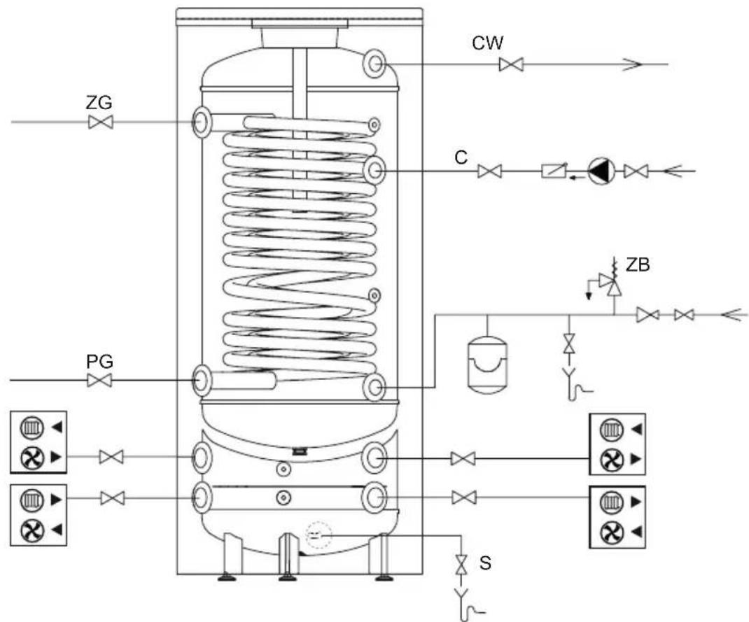
ZG PG CW C ZB SPlease follow water connection instructions below:
- install the T-connection with 6 bar* safety valve and the drain valve to the fitting of cold water inlet [ZW]. It's forbidden to install a cut-off valve (or any flow reducer) between the tank and the safety valve and on its outlet. The safety valve must be installed in such a place as to quickly let you notice the outgoing water,
- install the cylinder equipped with the safety valve to the water system,
- install the cut-off valve on cold water supply pipe.
Hot water outlet should be led to the connections in the upper part of the cylinder. Every cylinder is equipped with connection intended for its installation to the DHW circulation. The buffer tank can be assembled in the heating system:
- open system according to the current standards,
- closed system according to the current standards.
*Please note: use the safety valve matched to the heat's source. Installing a safety valve with inadequate capacity can result for excessive pressure increase in the cylinder and as a result a leakage. In this case, warranty does not cover damage caused.
text_image
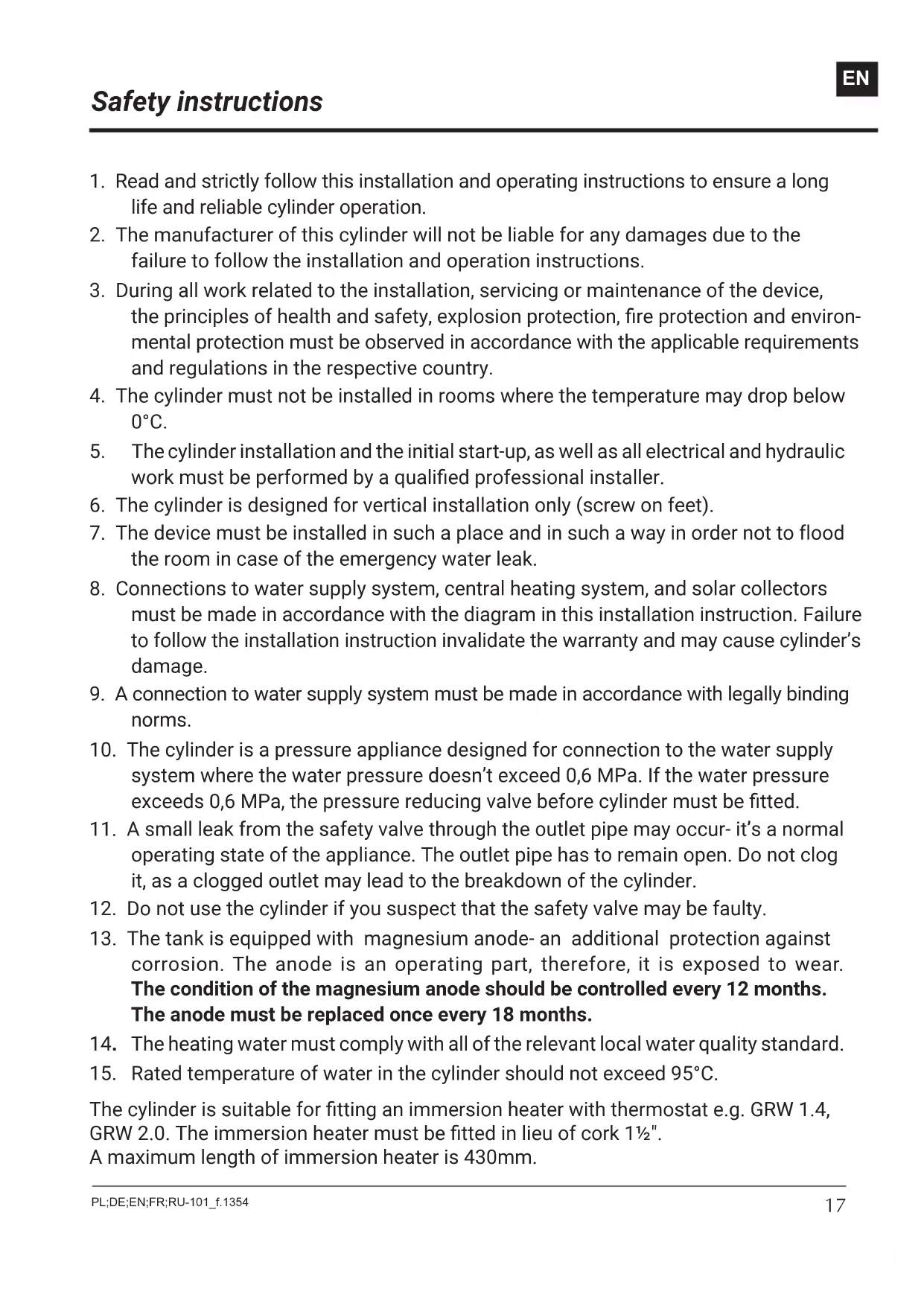
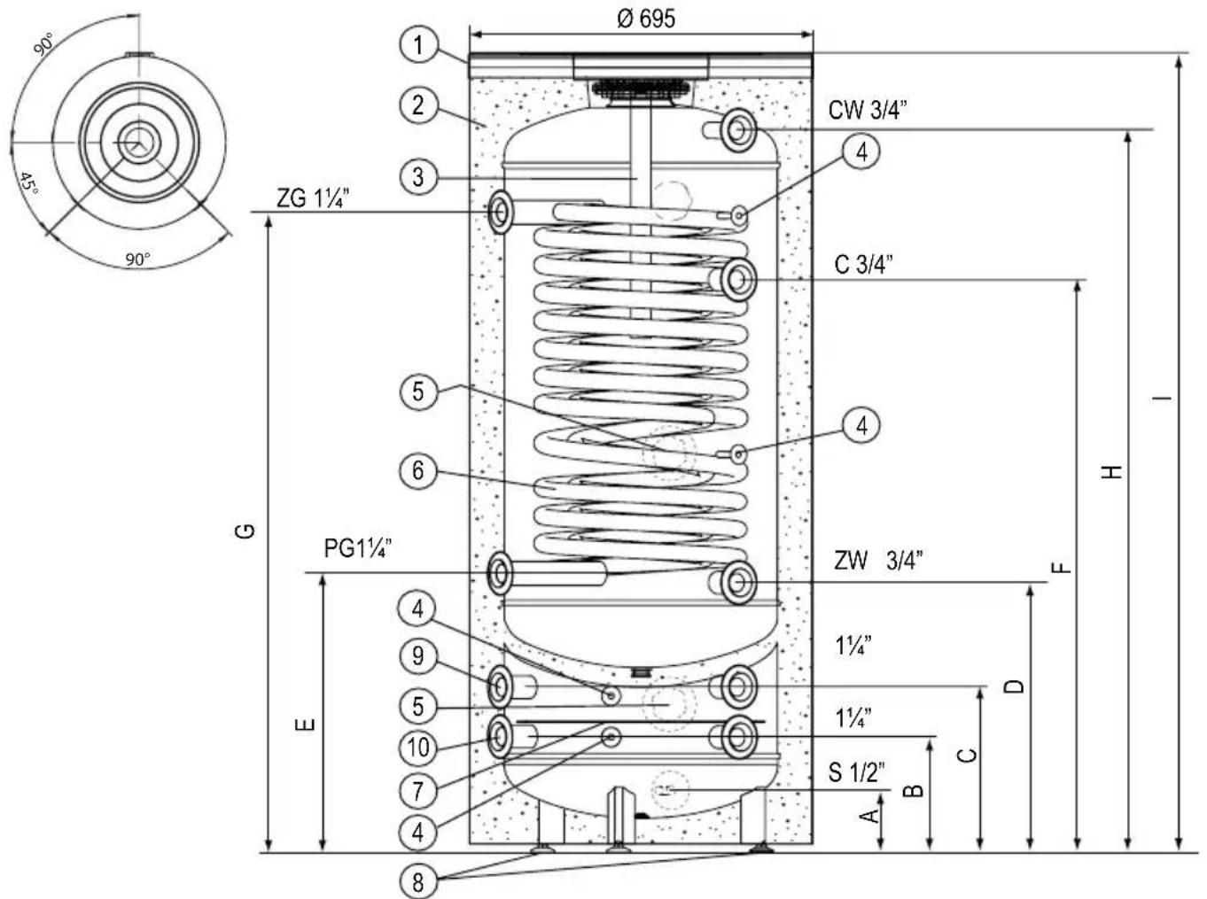
Ø 695 1 2 3 4 CW 3/4" ZG 1¼" C 3/4" 5 6 4 PG1¼" ZW 3/4" E 1¼" 1¼" S 1/2" A B C D 8 9 10 11 12 13 14 15 16 17 18 19 20 21 22 23 24 25 26 27 28 29 30 31 32 33 34 35 36 37 38 39 40 41 42 43 44 45 46 47 48 49 50 51 52 53 54 55 56 57 58 59 60 61 62 63 64 65 66 67 68 69 70 71 72 73 74 75 76 77 78 79 80[1] - lower lid
[2] - thermal insulation
[3] - magnesium anode
[4] - sensor pipe
[5] - immersion heater connection (cork 1½")
[6] - double heating coil
[7] - barrier
[8] - feet
[9] - ⓄCH feed
[10] - Ⓞ return
ZW - cold water
CW - hot water
ZG - heating medium supply of coil
PG - heating medium return of coil
C - circulation
S - buffer drain connection
A-I - dimensions described in the diagram

Dimensions SWVPC
| A 127 | |
| B 234 | |
| C 384 | |
| D 544 | |
| E | 563 |
| F | 1154 |
| G | 1289 |
| H | 1454 |
| I | 1610 |
Before the start-up make sure that the installation procedures have been carried out in accordance with the regulations included in this manual.
Cylinder must be filled with water:
- turn on the valve on cold water supply pipe,
- turn on the hot water outlet valve (water outflow without the air bubbles indicates that the tank is full),
- turn off the outlet valves.
Turn on the valves connecting cylinder with the central heating system and fill the surface area of buffer. To vent the buffer, you should use air vent on supply. Air vent is also recommended at the highest point of the coil supply connection. Check for water and heating medium leaks. Check out the safety valve performance in accordance with valve manufacturer's instruction.
Tank emptying
In order to empty the tank:
- turn off the valves which connect the buffer tank with central heating system,
- turn off the valves which connect the buffer tank with PC circuit,
- turn off the valve to connect the cold water inlet with cylinder,
- turn off the valve on the cold water inlet,
- turn on the drain valve.
Follow the guidelines below for safety and trouble-free cylinder operation:
- Check out the safety valve performance once every 14 days. Do not use the cylinder if the water does not come out (it indicates that the valve is broken).
- Clean inside of the cylinder periodically. The frequency of cleaning depends on the degree of water hardness. The cleaning should be done by a qualified person.
- The wear condition of the anode must be inspected annually.
- The anode must be replaced once every 18 months.
- anode rod replacement [3]: take off upper lid [1], take out an insulation ring, turn off the cut-off valve on cold water supply pipe, turn on the hot water valve (mixer tap), turn the drain valve on, drain as much water as you need to easily unscrew the anode rod (avoiding room flooding). Remove the cork and unscrew the anode rod.
- Heat up the water above 70^ periodically for hygiene reasons.
- Failures or malfunctions notify to the seller.
- Insulate the outlet pipe and heating coil connection pipes to minimise the heat loss (recommended).
Above activities are beyond of the scope of warranty service (should be done by the user).
How to deal with damage or irregularities
| Irregularity Instructions for conduct | |
| Water leakage from the tank | turn off the cold water supply valve and the CH system cut-off valves and contact the service |
| Excessive pressure build-up in the tank | |
| Pressure increase in the CH system | |
| Dirty water in the device | The tank should be cleaned of accumulated sediments - for this purpose, contact a specialized service company |
| Domestic Hot Water Cylinder With CH Buffer Tank SWVPC | |||
| Storage capacity | DHW | I | 235 |
| CH | 60 | ||
| Rated pressure | DHW | MPa | 0,6 |
| CH | 0,3 | ||
| Rated temperature °C | 95 | ||
| Minimum temp. of chilled water °C 6 | |||
| Surface area of heating m | 2 | 2,7 | |
| Capacity of coil dm | 3 | 17,5 | |
| Power of coil kW | 75* / 23** | ||
| Efficiency of coil l/h | 1900* / 575** | ||
| Weight (without water) kg | 157 | ||
| Magnesium anode M8 ø40 mm | 500 | ||
*80/10/45°C } - heating water temp./ supply water temp./ domestic water temperature; flowrate of **55/10/45°C } - heating water through the coil - 2,5m³/h.
Recycling and waste disposal
Removal of product and equipment:
Do not dispose of the product or equipment with household waste. Make sure that the product and all equipment is disposed of properly. Observe all applicable regulations.
Decomissioning
Used product must not be treated as a household waste. By disposing of this product correctly you will help to prevent potential negative consequences for the environment that could otherwise arise through inappropriate waste handling. For more detailed information about recycling of this product, please contact your local authority waste management service.