Elite Tactical DMR3 - Riflescope BUSHNELL - Free user manual and instructions
Find the device manual for free Elite Tactical DMR3 BUSHNELL in PDF.

| Product Type | Riflescope |
| Brand | Bushnell |
| Model | Elite Tactical DMR3 |
| Magnification | 3.5-21x |
| Objective Diameter | 50 mm |
| Tube Diameter | 34 mm |
| Reticle | G4P, First Focal Plane (FFP) |
| Tube Material | Aluminum |
| Weight | 35.5 oz (approx. 1006 g) |
| Length | 13.2 in (approx. 335 mm) |
| Eye Relief | 98 mm (at max magnification) |
| Field of View at 100 yds | 25.3 ft (at min magnification) |
| Parallax Adjustment | Side, from 25 yds to infinity |
| Elevation Turret | Exposed, non-locking, with RevLimiter™ zero stop |
| Windage Turret | Exposed, locking T-Lok™ |
| Click Value (Elevation/Windage) | 0.1 MIL per click |
| Max Travel (Elevation/Windage) | 32 MIL / 20 MIL |
| Travel per Revolution | 10 MIL |
| Lens Coating | Fully multi-coated + EXO Barrier™ |
| Argon Purge | Yes, waterproof |
| Power Source | None (passive optics) |
| Maintenance | Clean lenses with microfiber cloth, gentle air blower |
| Safety | Never look at the sun through the optic; mount properly on the firearm |
| Warranty | Ironclad Lifetime (as per defined lifespan) |
Frequently Asked Questions - Elite Tactical DMR3 BUSHNELL
User questions about Elite Tactical DMR3 BUSHNELL
0 question about this device. Answer the ones you know or ask your own.
Ask a new question about this device
Download the instructions for your Riflescope in PDF format for free! Find your manual Elite Tactical DMR3 - BUSHNELL and take your electronic device back in hand. On this page are published all the documents necessary for the use of your device. Elite Tactical DMR3 by BUSHNELL.
USER MANUAL Elite Tactical DMR3 BUSHNELL
natural_image
Close-up of a black BUTE TACTICAL and DMRA optical instrument (no text or symbols on the main body)DMR3
RIFLESCOPE OWNER'S GUIDE
Congratulations on your purchase of the Elite Tactical™ DMR3 Riflescope. Please read this owner's manual thoroughly to get the best use out of your riflescope.

WARNING: NEVER LOOK AT THE SUN THROUGH THE RIFLESCOPE OR ANY OTHER OPTICAL INSTRUMENT AS THIS MAY CAUSE PERMANENT EYE DAMAGE.
Elite Tactical DMR3 RIFLESCOPE FEATURES
Elite Tactical ^™ is constantly at the forefront of quality and innovation. The Elite Tactical DMR3 riflescopes are no exception. Fully-Multi Coated Optics, E.D. Prime glass, argon purging, and waterproof construction offer crisp, bright images in every environment.
All exterior lens surfaces have our EXO Barrier™ coating (in addition to full multi-coatings). EXO Barrier, quite simply, is the best protective lens coating technology Bushnell has ever developed. At the end of the coating process, EXO Barrier molecularly bonds to the lens and fills the microscopic pores in the glass. The result is an ultra-slick coating that repels water, oil, fog, dust, and debris; rain, snow, fingerprints, and dirt will not stick. In addition, EXO Barrier is built to last: the bonded coating will not fade with the passage of time or normal wear and tear.
All Elite Tactical DMR3 riflescope models feature:
- CLARITY - The best resolution and contrast in all lighting conditions.
- FIRST FOCAL PLANE - Maintains reticle scale at any magnification.
- HIGH LIGHT TRANSMISSION - Light transmission is increased 2% over DMR II Pro by enhancing the Ultra Wide Band Coating system to enable optimum brightness and true color in every lighting condition. Reticle elements are etched glass due to the complex pattern and recoil resistance requirements.
• DURABILITY - Machined from billet aluminum, the primary structural components are rock-solid. - REPEATABILITY - Click Value and Tracking are very precise, consistent, and reliable.
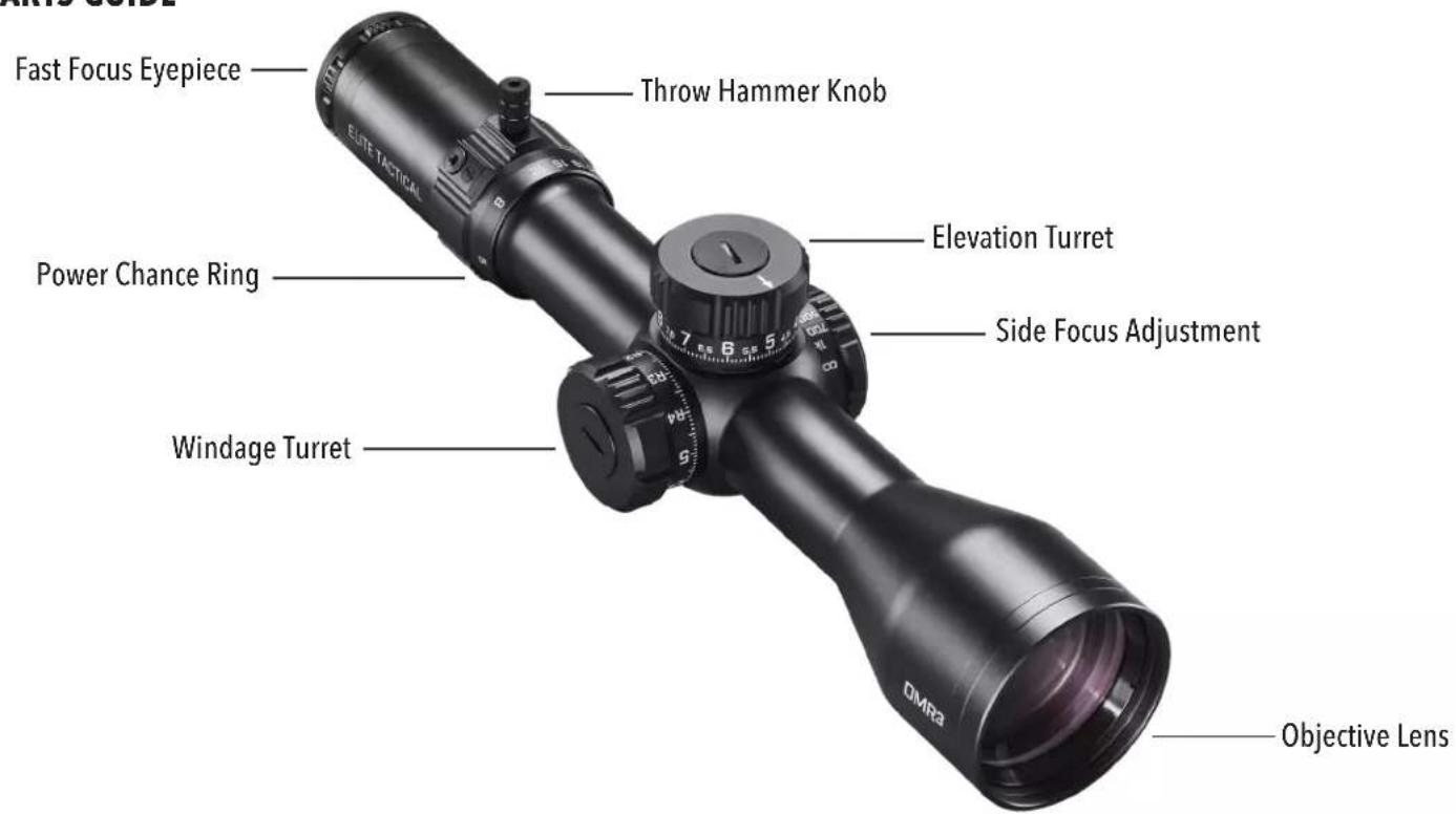
The Elite Tactical DMR3 scope covered in this manual includes a 34mm tube, G4P reticle, side focus parallax adjustment, and adjustable or removable PCR ThrowHammer knob locking windage turret, and non-locking elevation turret with RevLimiter zero-stop.
KEY ELEMENTS OF A SCOPE
- Objective Lens: This lens has three functions. First, it permits light to pass into the scope. Second, it determines resolution. Generally, a larger lens allows more light to enter the scope and resolve details better than a smaller one. Finally, it forms an image for the other lenses to magnify to a usable size. The image formed by this lens is upside down.
- Erector System: The erector system serves three functions. Its primary function is to erect the image (that is, flips the image right-side-up) and align it to the reticle. During this process, the primary magnification of the image takes place. The third function is a mechanical one. The erector lenses are housed in a tube constrained by a spherical joint at one end, while the other end of the tube is allowed to respond to windage or elevation turret adjustments.
- Reticle: In simple terms, the aiming device around which the scope is built. This element replaces the iron sight system of non-scoped rifles.
- Ocular or Eye Lens: This element provides the secondary and final magnification of the image and allows for reticle focusing independent of the target image focus.
PARTS GUIDE
MOUNTING YOUR SCOPE
Even with its technologically advanced design and features, your new scope will not perform at its best if not properly mounted. One of the most important contributing factors to your scope and rifle's combined accuracy is mount selection and the care with which mounting is done. Dependable mounts that secure your scope to the rifle will reward you with dependability and consistent accuracy.
Remember, not all scopes are compatible with all mounts on all rifles. If there is any doubt in your mind, you should seek the advice of your local retailer or gunsmith.

WARNING: A RIFLESCOPE SHOULD NEVER BE USED AS A SUBSTITUTE FOR EITHER A BINOCULAR OR SPOTTING SCOPE. IT MAY RESULT IN YOU INADVERTENTLY POINTING THE FIREARM AT SOMETHING YOU DO NOT WISH TO DESTROY.
PRELIMINARY SCOPE ADJUSTMENTS
Before installing the scope, we recommend calibrating the eyepiece's focus to your aiming eye's vision. Refocusing the ocular distance will sharpen the reticle focus and improve overall optical quality. It will also mitigate eye fatigue/strain when using the scope over prolonged periods. To refocus, hold the scope about 3 to 4 inches from your eye and point at the open sky or another flatly lit area such as a monotone painted wall.
Quickly glance into the scope. If the reticle appears blurred at first glance, the diopter requires adjustment. To make the first-pass, coarse adjustment, again look into the scope and quickly turn the diopter until the reticle image appears in focus (ignore the background image). Remember to take glances for the final-pass, fine adjustment, as your vision will naturally compensate for minor out-of-focus conditions with prolonged looks. Again, quickly glance into the scope and observe the reticle. If the reticle image is sharp, you may have gotten lucky, but the follow-up, fine adjustments are typically needed. If so, turn the diopter in a chosen direction by a small amount, then recheck the reticle focus. If better, continue trials in even smaller amounts to either side of the new diopter position. If worse, try the other direction. Repeat until the reticle is instantly in focus during a glance.
The diopter is now set up for your vision! Typically, only minor adjustments are required over the years. While the collar's internal friction should hold it in place with general handling, a semi-permanent witness mark (e.g., silver marker) may be added, OR an electrical tape wrap may be used for additional assurance against unwanted rotation.

WARNING: BEFORE BEGINNING THE MOUNTING PROCEDURE, BE SURE THE ACTION IS OPEN, THE CLIP OR MAGAZINE IS REMOVED, AND THE CHAMBER IS CLEAR. DO NOT ATTEMPT ANY WORK UNTIL YOUR FIREARM HAS BEEN CLEARED AND DETERMINED TO BE SAFE.

WARNING: IF THE SCOPE IS NOT MOUNTED FAR ENOUGH FORWARD, ITS REARWARD MOTION MAY INJURE THE SHOOTER WHEN THE RIFLE RECOILS.
While mounting your scope, we recommend that you DO NOT take shortcuts as it may damage either the mounting system or the scope. Each mounting system will have its instructions to follow, and it is best to read these first to ensure you understand them and have the necessary tools on hand.
We further recommend that you plan to go through the mounting procedure twice. The first time, to be sure everything fits together and functions properly. On the first run-through, please keep the following in mind:
- If applicable, before attaching base/accessory rail, clean the mounting holes in the receiver and the threads of the attaching screws with high-concentration IPA (isopropyl alcohol) to free them of oil or grease.
- If the mount manufacturer has recommended using a thread adhesive, do not use it on the first mounting trial. Once adhesive has been set, it is difficult to demount if anything needs correction, and residue should be removed before restarting.
- Be sure the mounting screws do not protrude into the receiver.
- When using twist-lock style rings, do not use the scope as a lever when installing. The initial resistance to turning may cause damage to the scope and is not covered by the warranty. Instead, we recommend using a wooden dowel or a matching diameter metal cylinder for seating the rings.
- Be sure the position of the scope does not interfere with the operation of the action.
- Be sure there is at least 3mm of clearance between the edges of the rings and any protruding surfaces such as the turret housing (saddle), power change ring, and the flare of the objective bell. Note the beginning of fillet transitions for the previously mentioned features. Also, be sure there is at least 3mm of clearance between the objective bell and the barrel.
- You should test the position of the scope for the proper eye relief. The scope rings should be left loose enough so that the scope will slide easily. Variable power scopes should be set at the highest magnification when performing this procedure. Mount the rifle and look through the scope in your normal shooting position. Unless only going to be used in a bench-rest (seated) or prone position (lying down), the modified-prone (leaning over a rest surface while standing or kneeling) position is recommended for more versatility.
- Test position the rifle for the proper cheek weld several times to ensure that your scope is positioned properly. If the scope is too high or low, consider altering the cheek weld riser position if adjustable. Alternatively, different height rings may be needed. Be sure adequate clearance is still maintained between the scope and rifle.
- When you are satisfied that everything is okay, add temporary reference markings (masking tape works well for this), demount, and start again. This time, add scope leveling (anti-cant) considerations while positioning the riflescope and securely fasten all hardware per the manufacturer's instructions. Securely fasten all hardware per the manufacturer's instructions. Typically, 15 lbf*in is the maximum fastener torque recommended for joints around the scope tube.
PARALLAX
You may have noticed that placing your eye at different positions (i.e., side-to-side OR up-and-down) behind the scope's eyepiece causes the reticle to appear to move around to different points on your target. This is a "parallax error" (target and reticle are not in the same focal plane), and it becomes more noticeable (and more of a problem) the greater the difference between target distance and side-focus setting. In some cases, parallax will not affect the bullet point of impact enough to be of significant concern. However, if you need to shoot at a target distance inside 25 yds, lower magnification settings will improve image quality.
USING THE SIDE FOCUS
The ET DMR3 model covered in this manual provides an adjustment for parallax compensation (side focus knob), which works by moving an optical element until the target (based on its distance) appears in the same plane of focus as the reticle. Your ET DMR3 scope can be focused as close as 25 yards. Just line up the estimated distance to your target with the index value or approximate the distance between indices. You will eliminate most of the aiming errors caused by parallax. You can double-check after setting the side focus by moving your head around from side to side behind the eyepiece; the point of aim should not shift if the side focus is correctly set. An alternative method is to look through the scope and turn the side focus knob until the target image, at whatever range, is sharply focused. Please note the distance markings on the dial are intended as reference points. Exact side focus adjustments may be needed to achieve a high resolution, parallax-free image. Also, note that the rifle and scope must be stationary when performing parallax error inspections. Any amount of induced movement will directly affect the point-of-aim and provide false feedback.
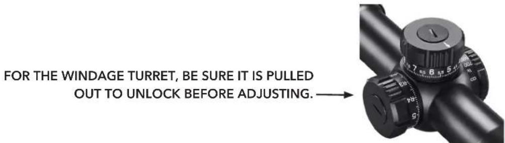
Your Elite Tactical Riflescope features a T-Lok™ (locking) windage turret, which provides audible and visual adjustment references. When the turret is pulled into the outward position, rotate in the right or left directions to make appropriate adjustments. Each increment of the turret provides an audible and tactile "click" that coincides with a visible reference point movement on the turret knob. Each "click" represents 1/10 MIL. After adjustments, the turret can be pushed back in to prevent movement or left extended and ready for further adjustments, if preferred.
After adjustments, you can reset the turret to zero by following the steps below:
Note: When resetting the windage turret, ensure the windage turret is in the locked (inboard) position.
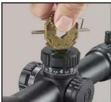
Use the included Bushnell multi-tool or a coin to remove the turret cap-screw found on top of the turret knob, do not displace the o-ring found under the turret cap-screw. Take care not to dislodge the O-Ring on the inner turret body. Also, avoid introducing any contaminants or debris into the exposed turret components.
Remove the turret knob and return it to the inner turret, with the "zero" mark on the knob lining up with the horizontal index line on the inner turret body.
Return the turret screw to the top of the knob and tighten it down, making sure the turret knob is in the locked position so the turret knob does not turn while tightening the screw.
RESETTING THE ELEVATION TURRET
Rotate the elevation turret knob counterclockwise to move the point-of-aim up or clockwise to move it down. One full revolution of the elevation dial will move the point of impact 10 MILS at any distance. After zeroing your rifle, you can reset the elevation turret to zero by following these steps:
- While holding the elevation turret steady with your free hand, use the included Bushnell multi-tool or a coin to remove the turret cap-screw found on top of the turret knob, being careful not to displace the o-ring found under the turret cap-screw.
- Remove the turret knob and return it to the inner turret with the "zero" mark on the knob lining up with the vertical index line on the inner turret body.
- Return the turret screw to the top of the knob and tighten it down, making sure to steady the turret knob with your free hand so the turret knob does not turn while tightening the screw.
natural_image
Close-up of a hand holding a gold-colored coin on a black optical gun scope (no visible text or symbols)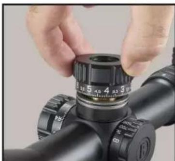
natural_image
Close-up of hands adjusting a black cylindrical object with adjustment knobs (no visible text or symbols)
natural_image
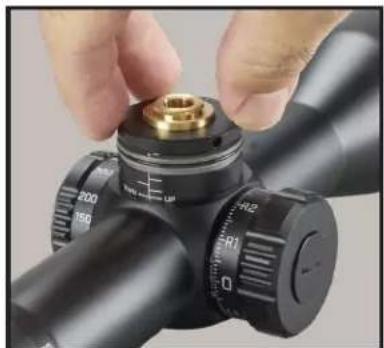
Close-up of hands adjusting a black precision optical device with adjustment knobs (no visible text or symbols)REVLIMITER™ (Zero Stop) INSTRUCTIONS
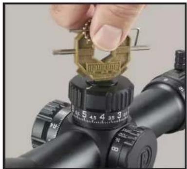
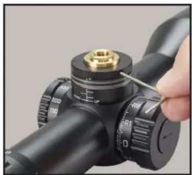
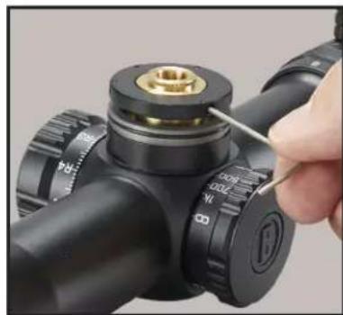
Step 1: Obtain a good zero on your rifle. Remove the turret knob cap-screw using the included Bushnell Multi-tool or a coin. (FIG. 1)
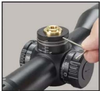
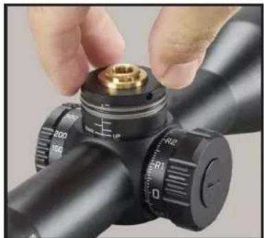
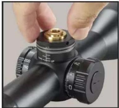
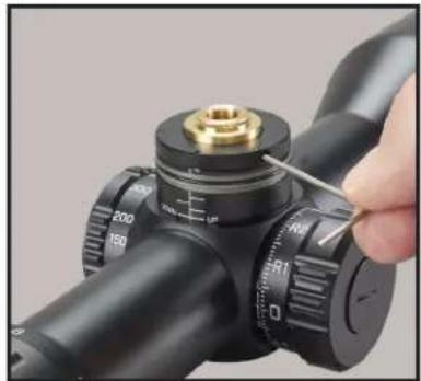
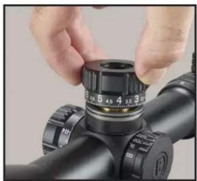
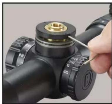
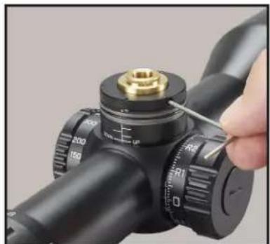
Step 2: Remove the turret knob and set it aside (FIG. 2A). Loosen the three set-screws found on the perimeter of the black inner locking ring 1 12 turns (using 1.5mm hex wrench-provided) (FIG. 2B). These screws are "captured" in the RevLimiter ring so that they cannot be completely removed and dropped or lost. Once these set-screws are loosened, the ring should fall down the turret shaft.
Step 3: Turn the RevLimiter disk clockwise until it contacts the fixed pin in the bottom of the turret (FIG. 3A). While holding the disk with gentle downward and clockwise pressure, gently tighten the three set screws in the RevLimiter disk to 2 lbf*in (FIG. 3B). (Do not overtighten screws. We recommended gripping the short leg of the L-key to reduce leverage). Your zero stop is set.
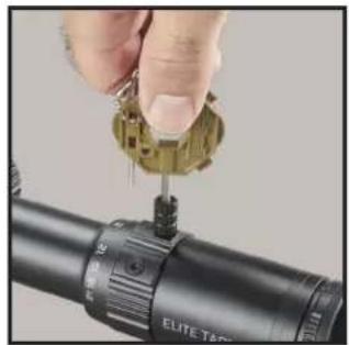
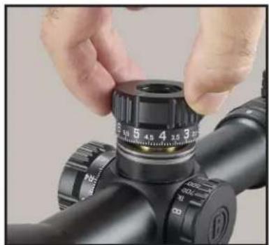
Step 4: Re-index the turret knob to zero and return the turret cap-screw to the top of the turret knob and tighten (FIG. 4).
natural_image
Close-up of a hand adjusting a golden coin on a black optical gun scope (no visible text or symbols)FIG. 1

natural_image
Close-up of hands adjusting a black optical device with a circular dial (no visible text or symbols)FIG. 2A

natural_image
Close-up of a hand adjusting a black cylindrical device with a brass fitting and a tool, no visible text or symbols.FIG. 2B

natural_image
Close-up of a hand adjusting a mechanical component with a brass fitting and adjustment knobs (no visible text or symbols)FIG. 3A
natural_image
Close-up of a hand using a tool to adjust a mechanical component with a brass fitting (no visible text or symbols)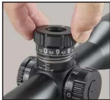
natural_image
Close-up of hands adjusting a black optical instrument with caliper and adjustment knobs (no visible text or symbols)FIG. 4FIG. 3B
If you wish to disengage the RevLimiter or change the setting, the sequence reverses the above. First, secure the disk in the upward position along the turret shaft to allow the turret to turn freely in the downward direction.
You may also choose to set the RevLimiter to a position that allows you to have POA travel below your absolute zero. A suggestion is to set it 0.2 to 0.5 MILS below absolute zero so that the turret may be "slipped" quickly and easily to account for ammunition selection or large atmospheric differences like when traveling to a location with significant elevation change. Just be mindful of the turret knob position before removing and return to the same position. It is not recommended to turn the inner turret body without the turret knob installed and secured.
VARIABLE POWER ADJUSTMENTS
Changing the magnification of the ET DMR3 is easily accomplished by grasping the new Throwhammer™ knob, which is fastened to the power change ring. The throw lever is factory installed but may be removed with the provided Bushnell Multi-tool. Use the lever to rotate the power change ring clockwise for higher magnification or counterclockwise for lower magnification. The magnification setting is identified by noting the number behind the stationary dot on the scope tube.
POWER CHANGE RING (PCR) Throwhammer™ ADJUSTMENT
- The Throwhammer™ knob Is factory installed in the neutral sweep (9 o'clock to 3 o'clock) position.
- The hardware hex sockets are 7/64 inches. Use the hex driver on the included Bushnell multi-tool to remove and reposition the related PCR parts.
- If the knob is undesired, remove and use the supplied spare screw to fill in the open tapped hole.
- A small amount of low-strength, removable thread-locker (e.g., Loctite® 242) may be used.
• The screws may be torqued to 8-10 lbf*in and the knob to 12-14 lbf*in. CAUTION: Do Not Overtighten
natural_image
Close-up of a hand using a precision tool to apply eyepiece onto a target (no text or symbols visible)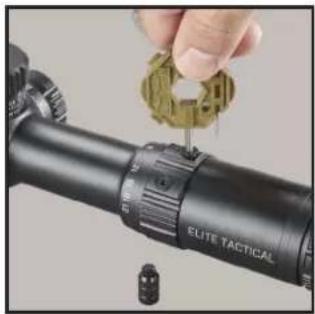
natural_image
Close-up of a hand adjusting a targeting gun with a green gear (no visible text or symbols)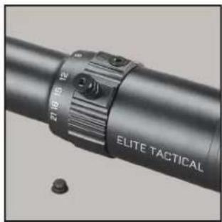
natural_image
Close-up of a black cylindrical device with a textured grip and labeled 'ELITE TACTICAL' (no additional text or symbols visible)FIRST FOCAL PLANE RETICLE
The ET DMR3 covered by this manual has a reticle located in the first focal plane. Therefore, the reticle will increase in size when the magnification is increased or vice versa. This feature allows the continued use of the MIL measurement system in the reticle, regardless of the power setting.
ELITE TACTICAL G4P PRECISION RETICLE
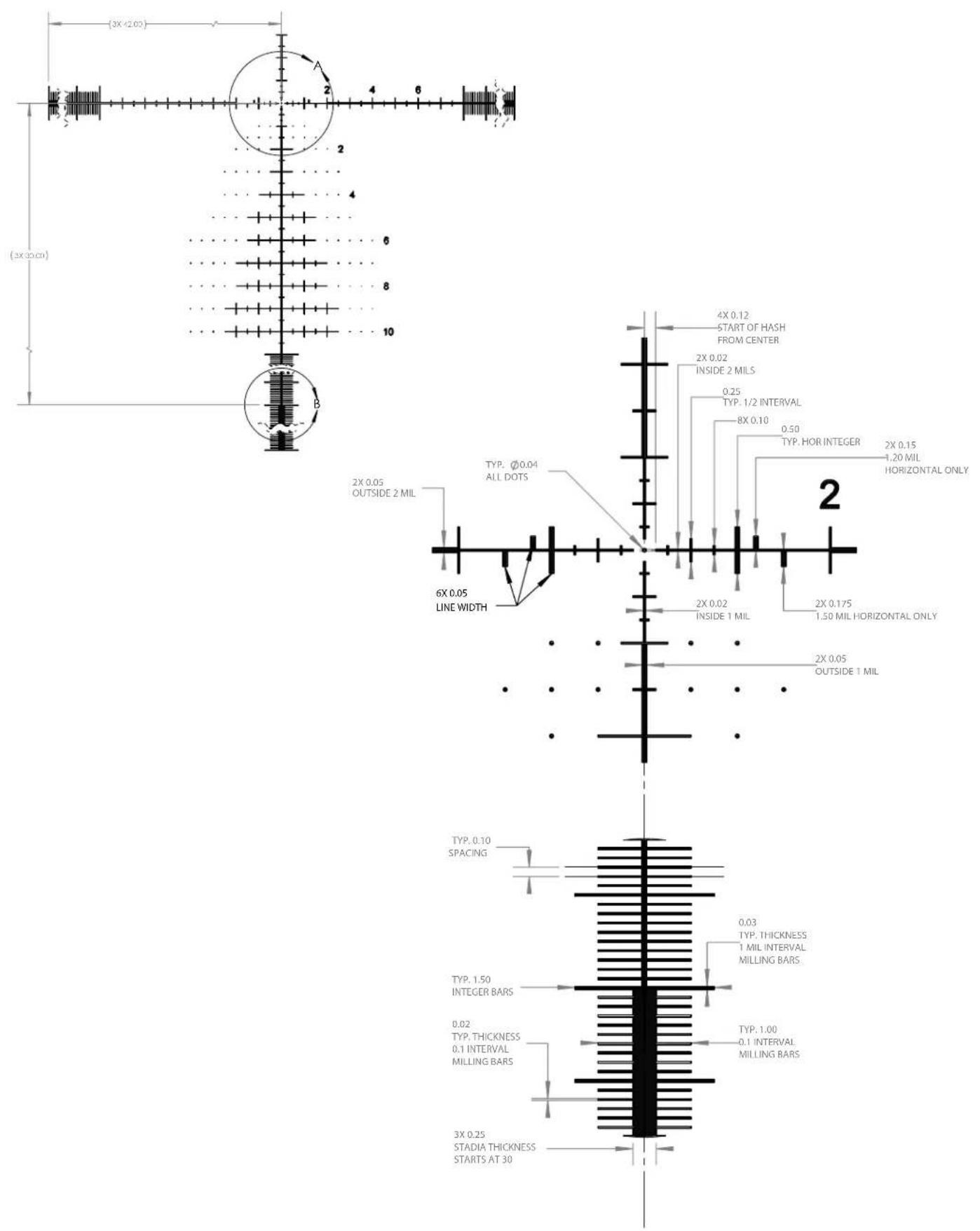
The G4P reticle, developed in conjunction with G.A. Precision, provides a clean reticle space for fast target acquisition. In contrast, the hybrid hash-dot tree provides for intuitive and efficient holds without using the turrets. The reticle is shown to the right, but the following pages will provide a more in-depth look.
THE HORIZONTAL CROSSHAIR
The numerically designated MIL markings extend from the center of the crosshairs outward to the right in 2 MIL increments on the horizontal crosshair. The numbers were removed on the left side of the reticle to keep the reticle plane clean, but the reference points coincide with the markings from the right side of the crosshair. Measurements from the center point to the right are as follows: 0.25 MIL, 0.5, 0.75, 1.0, 1.2, 1.5, 2.0, etc.
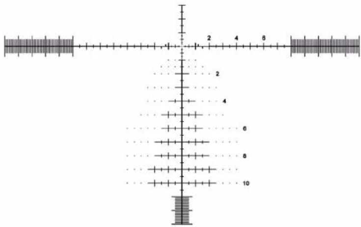
A carryover feature of the G4P reticle is bold hash marks on the horizontal stadia that provide hold-off marks for shooting at moving targets. These "mover marks" are located at 1, 1.2, and 1.5 MILS to the left and right of the center of the crosshairs. These are for typical target speeds at given distances. Use a ballistic solver tool to determine the correct mover hold for your firearm and ammo combination.
1/2 MIL and 1 MIL markings stop extending at the 8 MIL position. Within the milling bar sections of the reticle, 1 MIL increments are designated by the longer hash marks, which measure 1.5 MIL in height from top to bottom. Intermediate 0.1 MIL markings are visible between 1 MIL marking, 1 MIL height and extend through the FOV. The 0.1 MIL markings provide you with a very precise horizontal measurement of your target. For example, at 30 MILS from the center, a quick-acquisition solid bar is 0.25 MIL tall. This is only visible at low magnification settings.
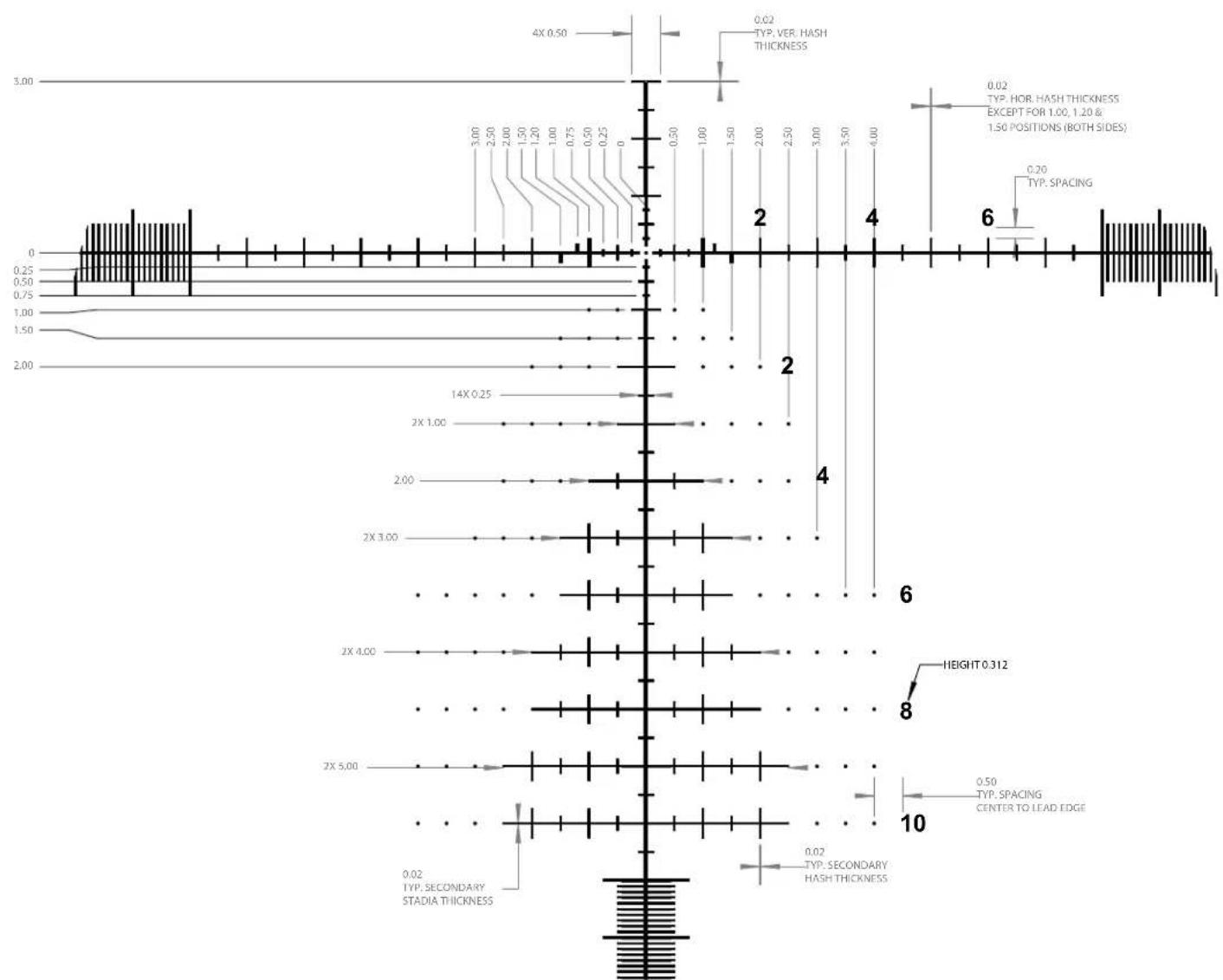
THE VERTICAL CROSSHAIR
The vertical crosshair places the numerically designated MIL markings on only the right side, like the horizontal crosshair. Once again, the numerically designated markings are in 2 MIL increments with 0.25 MIL interval hash marks inside of 1 MIL and every 0.5 MIL interval outside of 1 MIL. The 11th MIL measurement down the reticle converts to 0.1 milling bars, and the solid 0.25 MIL wide quick-acquisition bar starts at 30 MILS from the main horizontal stadia. The horizontal hashes begin to elongate for windfall references, and floating dots are applied for additional holds without crowding the reticle space to maintain the relatively clear appearance of the G-series design that familiar users know.
PRELIMINARY SIGHTING-IN
You can save a significant amount of expense and frustration by pre-sighting the scope to the rifle before live-firing. This is also critical if your berm is small.
Two basic methods can be used for pre-sighting your scope. Method one is to use a Bushnell® Bore Sighter (laser, magnetic or standard). The use of a Bore Sighter saves time and ammunition and is the system most often used by gunsmiths.
The second method is traditional bore sighting. Rifles are typically sighted-in (aka zeroed) at 100yds, but this is the user's preference. The reticle is located in the first focal plane so that the reticle graduations may be used for reference at any magnification setting.
BORE SIGHTING METHOD
- Place a target at 100 yards.
- Remove the bolt from the rifle.
- Place the rifle on sandbags or shooting rest.
- Set the scope to approximately 1/3 of the magnification range.
- Peer through the bore from the receiver end and adjust the rifle's position to center the target in the bore (Fig. A).
- Without moving the rifle, look into the scope and note the position of the reticle on the target. Grasp the turret and turn it in the appropriate directions indicated by the arrows to center the reticle on the bull's eye (Fig. B). Each "click" or increment on the Adjustment Scale Ring will change the bullet impact by the laser engraved value on the top of your scope model's turret. For reference, 0.1 MIL is 1cm @ 100m OR 0.36in @ 100yd.
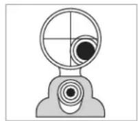
Fig. A
Reticle not in alignment
Fig. B
Reticle in alignment
FINAL SIGHTING-IN

WARNING: SINCE THIS PROCEDURE INVOLVES LIVE FIRE, YOU SHOULD DO THIS AT AN APPROVED RANGE OR OTHER SAFE AREA. CHECK BORE FOR OBSTRUCTIONS. AN OBSTRUCTED BORE MAY CAUSE INJURY TO YOU AND OTHERS NEARBY. EYE AND EAR PROTECTION ARE RECOMMENDED.
From a steady rest position, fire two or three rounds at a 100-yard target. Note the impact of the bullet on the target and adjust the windage and elevation dials as needed. A shorter distance may be chosen if the target size or ammunition is limited. Use this as a coarse adjustment, then final zeroing distance as the fine adjustment target distance.
To move the point-of-impact, adjust the dial direction to match the desired change. The adjustments on your riflescope model are marked in MILS (milliradians), and the point of impact at any distance will change by .1 MIL for each click of the windage or elevation adjustment. One full revolution of turret adjustment=10 MILS.
CARING FOR YOUR RIFLESCOPE
Your scope needs very little maintenance. Exterior metal surfaces should be kept clean. A light dusting with a slightly dampened soft cloth is enough in most cases.
Your new scope features windage and elevation turrets sealed against water and dust ingress. Still, care must be taken to avoid introducing contaminants or debris into the turret components while the turret knobs are removed.
We also recommend that lens covers are utilized when the scope is not being used. Lenses should be inspected regularly and occasionally cleaned depending on contaminant type and amount. Dust, dirt, and fingerprints that collect on the lens surfaces can degrade image quality. Although lens cleaning is not difficult, it does require care and some patience. Note that it is not necessary to keep the lens perfectly clean at all times.
For typical dust accumulation, start using a blow-out bulb (using your mouth isn't ideal due to the moisture that will cause some particulates to adhere more readily) to dislodge loose debris. A lens brush may also be used. Then use your breath to moisten the surface and very gently wipe it out from the center in a spiraling motion.
If the scope has been used outside during a rainstorm and has heavy spotting from mud, it is recommended to introduce a low-pressure water source like a faucet or bottle of water. If using a garden hose, remove the nozzle and reduce the flow rate.
NOTE: Any cloth must be clean and should be microfiber like the included SPUDS ^® , OR it may be a high-quality automotive paint finish cloth (e.g., 10 per "rag"). Single-use lens tissue is also acceptable, but facial tissue is not. Do not use solvents (this includes lens wipes with IPA). Do not use paper towels or cotton cloths.
G4P Reticle Detail
G4P Reticle Detail (cont.)
other
| Measurement | Value | |-------------|-------| | 4X 0.50 | 3.00 | | 1.50 | 2.50 | | 2X 3.00 | 2.00 | | 2X 4.00 | 1.50 | | 2X 5.00 | 1.00 | | 2X 6 | 0.75 | | 2X 7 | 0.50 | | 2X 8 | 0.25 | | 2X 9 | 0.25 | | 2X 10 | 0.50 | | Height | 3.00 | | Spacing | 2.50 | | Spacing | 2.00 | | Spacing | 1.50 | | Spacing | 1.00 | | Spacing | 0.50 | | Spacing | 0.25 | | Spacing | 0 | | Secondary Stadia Thickness | 1.50, 2.00, 2.50, 3.00, 3.50, 4.00, 4.50, 5.00, 5.50, 6.00, 6.50, 7.00, 7.50, 8.00, 8.50, 9.00, 9.50, 10.00, 10.50, 11.00, 11.50, 12.00, 12.50, 13.00, 13.50, 14.00, 14.50, 15.00, 15.50, 16.00, 16.50, 17.00, 17.50, 18.00, 18.50, 19.00, 19.50, 20.00, 20.50, 21.00, 21.50, 22.00, 22.50, 23.00, 23.50, 24.00, 24.50, 25.00, 25.50, 26.00, 26.50, 27.00, 27.50, 28.00, 28.50, 29.00, 29.50, 30.00, 30.50, 31.00, 31.50, 32.00, 32.50, 33.00, 33.50, 34.00, 34.50, and 35.00, respectively. Typical Hash Thickness Typ.HOR HASH THICKNESS Except for: [1.00, 1.20 & .] 1.50 POSITIONS (both sides) Typ.SPACING| SKU | Mag x Obj. Diameter | Reticle | Elevation Turrets | Windage Turrets | Elev. Travel (MIL) | Windage Travel (MIL) | Travel per Revolution (MIL) | Tube Diameter(mm) | Minimum Parallax (Yards) | Eye Relief, Max Mag. | Field of View @100 Yds (Ft) | Length (in) | Weight (oz) |
| ETDMR3G4 3,5 | 21x50 G4P FFP | Exposed, Non-Locking w/RevLimiterTM Zero-Stop | Exposed, Locking | 32 20 | 10 34 25 98 mm 25,3 | -5,1 13,2 | 35,5 |
DO YOU NEED TO SEND YOUR SCOPE TO US?
Before returning your scope for service, you should check the following points to make sure the problem is with the scope:
- Check the mounting system and rings for looseness or misalignment.
- Check to be sure the barrel and action are properly bedded and all receiver screws are tight.
- Check to be sure the mounting system allows sufficient clearance between the objective bell and the barrel.
- Check to be sure you are using the same type and weight ammunition that you used for sighting-in.
- Consider moving riflescope over to a different rifle of known function and/or placing an alternative riflescope onto the primary rifle that is assumed to be non-suspect. The goal is to see if the concern follows the riflescope or remains with the rifle.


NO RECEIPT

FULLY

WORKMANSHIP

MATERIALS
BUSHNELL IRONCLAD WARRANTY
Products manufactured on or after June 2020 are covered by the Bushnell Ironclad Warranty. The Ironclad Warranty is a full lifetime warranty that covers the lifetime of this Product. Each Product has a defined lifetime; lifetimes can range from 1 to 30 years. This Product's lifetime can be found at the website listed below and/or on the Bushnell webpage specific to this Product.
We warrant that this Product is free from defects in materials and workmanship and will meet all represented performance standards for the lifetime of this Product. If this Product isn't working properly due to a covered defect, we will, at our option, either repair or replace it and ship it back to you at no charge. This warranty is fully transferable and does not require a receipt, warranty card, or product registration. This warranty does not cover the following: electronic components; batteries; cosmetic damage; damage caused by failing to properly maintain the product; loss; theft; damage as a result of unauthorized repair, modification, or disassembly; intentional damage, misuse, or abuse; and ordinary wear and tear. This Warranty will be void if the date stamp or other serialization codes have been removed from the Product.
To view the full warranty and find details on how to request service under the warranty, go to our website at www.bushnell.com/warranty. Alternatively, you can request a copy of the warranty by calling us at 1-800-423-3537 or writing to us at one of the following addresses:
IN U.S.A. Send To:
IN CANADA Send To:
Bushnell Outdoor Products
Bushnell Outdoor Products
Attn.: Repairs
Attn.: Repairs
9200 Cody 140 Great Gulf Drive, Unit B
Overland Park, Kansas 66214 Vaughan, Ontario L4K 5W1
For products purchased outside the United States or Canada please contact your local dealer for applicable warranty information.
This warranty gives you specific legal rights.
You may have other rights which vary from country to country.
©2021 Bushnell Outdoor Products
natural_image
Close-up of a hand adjusting a gold-colored mechanical component on a black optical gun scope (no visible text or symbols)
natural_image
Close-up of hands adjusting a black optical device with a circular dial (no visible text or symbols)
natural_image
Close-up of hands adjusting a black optical bench with a dial (no visible text or symbols)INSTRUCTIONS REVLIMITER™ (zéro stop)
natural_image
Close-up of a hand adjusting a golden coin on a black optical gun scope (no visible text or symbols)FIG. 1

natural_image
Close-up of hands adjusting a black optical device with a dial (no visible text or symbols)FIG. 2A

natural_image
Close-up of a hand adjusting a black cylindrical device with a brass fitting and a tool, no visible text or symbols.FIG. 2B

natural_image
Close-up of a hand adjusting a mechanical component with a brass fitting (no visible text or symbols)FIG. 3A
natural_image
Close-up of a hand using a tool to adjust a mechanical component with a brass fitting (no visible text or symbols)
natural_image
Close-up of a black precision optical instrument with adjustment knobs and a hand adjusting the lens (no visible text or symbols)FIG. 4FIG. 3B
natural_image
Close-up of a hand adjusting a mechanical component on a targeting scope (no visible text or symbols)
natural_image
Close-up of a hand holding a small green object next to a black target range (no text or symbols visible)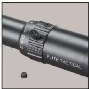
natural_image
Close-up of a metallic cylindrical device with a textured grip and labeled 'ELITE TACTICAL' (no additional text or symbols visible)RÉTICULE AU PREMIER PLAN DE MISE AU POINT
other
| Measurement | Value | |-------------|-------| | 4X 0.50 | 3.00 | | 1.50 | 2.50 | | 2X 3.00 | 2.00 | | 2X 4.00 | 1.50 | | 2X 5.00 | 1.00 | | 2X 6 | 0.75 | | 2X 7 | 0.50 | | 2X 8 | 0.25 | | 2X 9 | 0.25 | | 2X 10 | 0.25 | | Height | 3.00 | | Spacing | 2.50 | | Spacing | 2.00 | | Spacing | 1.50 | | Spacing | 1.00 | | Spacing | 0.50 | | Spacing | 0.25 | | Spacing | 0 | | Secondary Stadia Thickness | 1.50, 2.00, 2.50, 3.00, 3.50, 4.00, 4.50, 5.00, 5.50, 6.00, 6.50, 7.00, 7.50, 8.00, 8.50, 9.00, 9.50, 10.00, 10.50, 11.00, 11.50, 12.00, 12.50, 13.00, 13.50, 14.00, 14.50, 15.00, 15.50, 16.00, 16.50, 17.00, 17.50, 18.00, 18.50, 19.00, 19.50, 20.00, 20.50, 21.00, 21.50, 22.00, 22.50, 23.00, 23.50, 24.00, 24.50, 25.00, 25.50, 26.00, 26.50, 27.00, 27.50, 28.00, 28.50, 29.00, 29.50, 30.00, 30.50, 31.00, 31.50, 32.00, 32.50, 33.00, 33.50, 34.00, 34.50, and 35.00, respectively. Typical Hash Thickness Typical Hash Thickness Typical Hash Thickness Typical Hash Thickness Typical Hash Thickness Typical Hash Thickness Typical Hash Thickness Typical Hash Thickness Typical Hash Thickness Typical Hash Thickness Typical Hash Thickness Typical Hash Thickness Typical Hash Thickness Typical Hash Thickness Typical Hash Thickness Typical Hash Thickness Typical Hash Thickness Typical Hash Thickness Typical Hash Thickness Typical Hash Thickness Typical Hash ThicknessBushnell Outdoor Products
Bushnell Outdoor Products
Attn.: Repairs
Attn.: Repairs
9200 Cody 140 Great Gulf Drive, Unit B
Overland Park, Kansas 66214 Vaughan, Ontario L4K 5W1
©2021 Bushnell Outdoor Products
natural_image
Close-up of a black mechanical lever dial with adjustment knobs and a pointer (no visible text or symbols)natural_image
Close-up of a hand adjusting a gold-colored mechanical component on a black optical gun (no visible text or symbols)
natural_image
Close-up of hands adjusting a black optical bench with adjustment knobs (no visible text or symbols)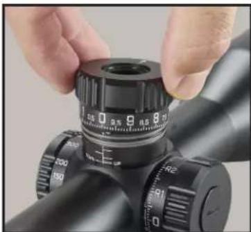
natural_image
Close-up of hands adjusting a black cylindrical optical device with adjustment knobs (no visible text or symbols)natural_image
Close-up of a hand adjusting a gold-colored mechanical component on a black optical gun (no visible text or symbols)FIG. 1

natural_image
Close-up of hands adjusting a black optical device with a dial (no visible text or symbols)FIG. 2A

natural_image
Close-up of a hand adjusting a black mechanical component with a brass fitting and a dial (no visible text or symbols)FIG. 2B
natural_image
Close-up of a hand adjusting a mechanical component with a brass fitting and adjustment knobs (no visible text or symbols)FIG. 3A

natural_image
Close-up of a hand using a precision tool to adjust a black cylindrical device with a brass fitting (no visible text or symbols)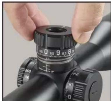
natural_image
Close-up of hands adjusting a black optical instrument with caliper and adjustment knobs (no visible text or symbols)FIG. 4FIG. 3B
natural_image
Close-up of a hand using a tool to apply eyepiece onto a target (no text or symbols visible)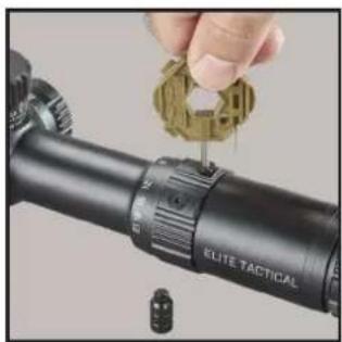
natural_image
Close-up of a hand adjusting a tactical scope on a black cylindrical optical device (no text or symbols visible)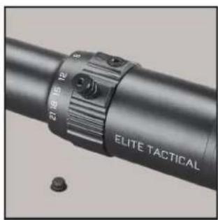
natural_image
Close-up of a metallic cylindrical device with a labeled grip and two small bolts (no readable text or symbols)other
| Dimension | Value | | --------- | ----- | | 4X 0.50 | 0.50 | | 14X 0.25 | 14X | | 2X 1.00 | 2X | | 2X 3.00 | 2X | | 2X 4.00 | 2X | | 2X 5.00 | 2X | | Height 0.312 | 0.312 | | TYP. SPACING | Center to Lead Edge | | Secondary Hash Thickness | Secondary Hash Thickness | | Vertical Hash Thickness | Vertical Hash Thickness | | Horizontal Position | Horizontal Position (Both Sides) | | Horizontal Spacing | Horizontal Spacing | | Horizontal Height | Horizontal Height (Both Sides) | | Vertical Hash Thickness | Vertical Hash Thickness | | Vertical Spacing | Vertical Spacing | | Vertical Height | Vertical Spacing | | Vertical Spacing | Vertical Spacing | | Vertical Height | Vertical Spacing | | Vertical Spacing | Vertical Spacing | | Vertical Height | Vertical Spacing | | Vertical Spacing | Vertical Spacing | | Vertical Spacing | Vertical Spacing | | Vertical Spacing | Vertical Spacing | | Vertical Spacing | Vertical Spacing | | Vertical Spacing | Vertical Spacing | | Vertical Spacing | Vertical Spacing | | Vertical Spacing | Vertical Spacing | | Vertical Spacing | Vertical Spacing | | Vertical Spacing | Vertical Spacing | | Vertical Spacing | Vertical Spacing | | Vertical Spacing | Vertical Spacing | | Vertical Spacing --> STADIA THICKNESS 0.02 TYP. SECONDARY STADIA THICKNESS 0.02 TYP. SECONDARY HASH THICKNESS 0.50 TYP. SPACING CENTER TO LEAD EDGE 0.50 TYP. SPACING CENTER TO LEAD EDGE 0.20 TYP. SPACING CENTER TO LEAD EDGE 0.20 TYP. SPACING CENTER TO LEAD EDGE 0.25 TYP. SPACING CENTER TO LEAD EDGE 0.50 TYP. SPACING CENTER TO LEAD EDGE 1.00 TYP. SPACING CENTER TO LEAD EDGE 1.50 TYP. SPACING CENTER TO LEAD EDGE 2X 1.00 2X 3.00 2X 4.00 2X 5.00 2X 6.00 2X 7.00 2X 8.00 2X 9.00 2X 10.00 2X 11.00 2X 12.00 2X 13.00 2X 14.00 2X 15.00 2X 16.00 2X 17.00 2X 18.00 2X 19.00 2X 20.00 2X 21.00 2X 22.00 2X 23.00 2X 24.00 2X 25.00 2X 26.00 2X 27.00 2X 28.00 2X 29.00 2X 30.00 2X 31.00 2X 32.00 2X 33.00 2X 34.00 2X 35.00 2X 36.00 2X 37.00 2X 38.00 2X 39.00 2X 40.00 2X 41.00 2X 42.00 2X 43.00 2X 44.00 2X 45.00 2X 46.00 2X 47.00 2X 48.00 2X 49.00 2X 50.00 2X 51.00 2X 52.00 2X 53.00 2X 54.00 2X 55.00 2X 56.00 2X 57.00 2X 58.00 2X 59.00 2X 60.00 2X 61.00 2X 62.00 2X 63.00 2X 64.00 2X 65.00 2X 66.00 2X 67.00 2X 68.00 2X 69.00 2X 70.00Technical Specifications
Bushnell Outdoor Products Bushnell Outdoor Products
Attn.: Repairs
Attn.: Repairs
9200 Cody 140 Great Gulf Drive, Unit B
Overland Park, Kansas 66214 Vaughan, Ontario L4K 5W1
© 2021 Bushnell Outdoor Products
natural_image
Close-up of a black cylindrical optical device with adjustment knobs and a dial (no visible text or symbols)natural_image
Close-up of a hand adjusting a golden coin on a black optical gun scope (no visible text or symbols)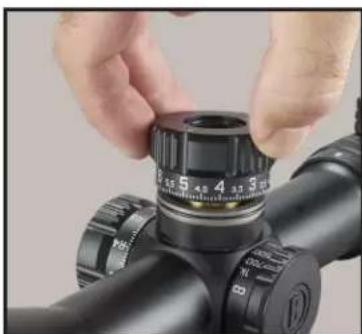
natural_image
Close-up of hands adjusting a black optical device with a dial (no visible text or symbols)
natural_image
Close-up of hands adjusting a black optical bench with adjustment knobs (no visible text or symbols)natural_image
Close-up of a hand inserting a gold coin into a black optical gun scope (no text or symbols visible)FIG. 1
natural_image
Close-up of hands adjusting a black optical bench with adjustment knobs (no visible text or symbols)FIG. 2A
natural_image
Close-up of a hand adjusting a black mechanical component with a brass fitting (no visible text or symbols)FIG. 2B
natural_image
Close-up of hands adjusting a mechanical component with a brass fitting and adjustment knobs (no visible text or symbols)FIG. 3A
natural_image
Close-up of a hand adjusting a black cylindrical device with a brass fitting, showing no visible text or symbols.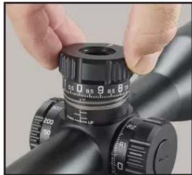
natural_image
Close-up of hands adjusting a black optical instrument with caliper and adjustment knobs (no visible text or symbols)FIG. 4FIG. 3B
natural_image
Close-up of a hand adjusting a gold-colored mechanical component on a black cylindrical optical device (no visible text or symbols)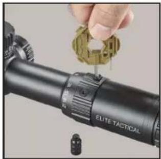
natural_image
Close-up of a hand adjusting a targeting tool on a black optical optical pole, with no visible text or symbols.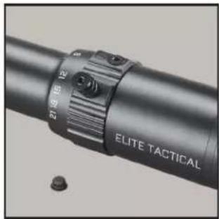
natural_image
Close-up of a black cylindrical device with a metallic strap and labeled 'ELITE TACTICAL' (no additional text or symbols visible)ABSEHEN IN DER ERSTEN BRENNEBENE
Technical Specifications
Bushnell Outdoor Products Bushnell Outdoor Products
Attn.: Repairs
Attn.: Repairs
9200 Cody 140 Great Gulf Drive, Unit B
Overland Park, Kansas 66214 Vaughan, Ontario L4K 5W1
© 2021 Bushnell Outdoor Products
natural_image
Close-up of a hand adjusting a gold-colored object on a black optical gun scope (no visible text or symbols)
natural_image
Close-up of hands adjusting a black optical component with a dial (no visible text or symbols)
natural_image
Close-up of hands adjusting a black optical instrument with a dial and adjustment knobs (no visible text or symbols)ISTRUZIONI PER REVLIMITER™ (Zero Stop)
natural_image
Close-up of a hand adjusting a gold-colored mechanical component on a black optical gun (no visible text or symbols)FIG. 1
natural_image
Close-up of hands adjusting a black cylindrical device with a dial (no visible text or symbols)FIG. 2A
natural_image
Close-up of a hand adjusting a black cylindrical device with a brass fitting and a dial (no visible text or symbols)FIG. 2B
natural_image
Close-up of hands adjusting a mechanical component with a brass fitting (no visible text or symbols)FIG. 3A
natural_image
Close-up of a hand adjusting a black cylindrical device with a brass fitting, showing no visible text or symbols.
natural_image
Close-up of a black optical instrument with adjustment knobs and a hand adjusting it (no visible text or symbols)FIG. 4FIG. 3B
natural_image
Close-up of a hand using a precision tool to apply eyepiece onto a target (no text or symbols visible)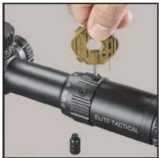
natural_image
Close-up of a hand adjusting a targeting tool with a golden gear (no visible text or symbols)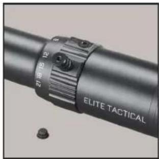
natural_image
Close-up of a black cylindrical device with a circular adjustment knob labeled 'Elite Tactical' and a small bolt on the side (no readable text beyond label)RETICOLO DEL PRIMO PIANO FOCALE
Technical Specifications
Bushnell Outdoor Products Bushnell Outdoor Products
Attn.: Repairs
Attn.: Repairs
9200 Cody 140 Great Gulf Drive, Unit B
Overland Park, Kansas 66214 Vaughan, Ontario L4K 5W1
©2021 Bushnell Outdoor Products

©2021 Bushnell Outdoor Products
Bushnell, ^TM , ^® , denote trademarks of Bushnell Outdoor Products
www.bushnell.com
9200 Cody, Overland Park, KS 66214