731303 - Riflescope BUSHNELL - Free user manual and instructions
Find the device manual for free 731303 BUSHNELL in PDF.
| Product type | Red dot sight (reflex) |
| Model | TRS-25 (ref. 731303) |
| Brand | BUSHNELL |
| Power source | 1 CR2032 button cell battery (3V) |
| Battery life | Varies with brightness setting; reduced by extreme cold |
| Mounting | Picatinny MIL-Std 1913 or Weaver rail (included) |
| Adjustments | Elevation and windage; 1 click = 13 mm at 100 m |
| Eye relief | Unlimited |
| Parallax | Parallax-free (design) |
| Lens covers | Removable with rubber cord (included) |
| Intended use | Rifles, carbines, pistols |
| Weather resistance | Waterproof when covers and caps are properly sealed; resistant to splashes, water, mud, snow |
| Maintenance | Clean lenses with a special cloth; blow to remove debris |
| Warranty | 2 years (material and manufacturing defects) |
| Certifications | FCC Class B compliant |
Frequently Asked Questions - 731303 BUSHNELL
User questions about 731303 BUSHNELL
0 question about this device. Answer the ones you know or ask your own.
Ask a new question about this device
Download the instructions for your Riflescope in PDF format for free! Find your manual 731303 - BUSHNELL and take your electronic device back in hand. On this page are published all the documents necessary for the use of your device. 731303 by BUSHNELL.
USER MANUAL 731303 BUSHNELL
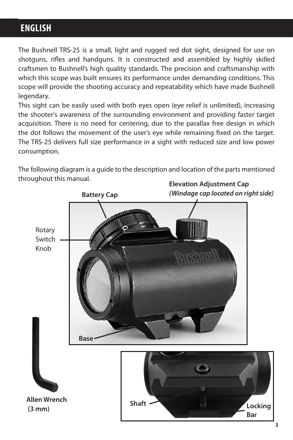
The Bushnell TRS-25 is a small, light and rugged red dot sight, designed for use on shotguns, rifles and handguns. It is constructed and assembled by highly skilled craftsmen to Bushnell's high quality standards. The precision and craftsmanship with which this scope was built ensures its performance under demanding conditions. This scope will provide the shooting accuracy and repeatability which have made Bushnell legendary.
This sight can be easily used with both eyes open (eye relief is unlimited), increasing the shooter's awareness of the surrounding environment and providing faster target acquisition. There is no need for centering, due to the parallax free design in which the dot follows the movement of the user's eye while remaining fixed on the target. The TRS-25 delivers full size performance in a sight with reduced size and low power consumption.
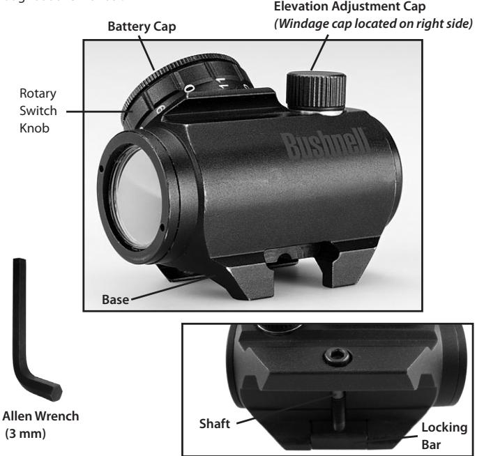
The following diagram is a guide to the description and location of the parts mentioned throughout this manual.
SETUP AND OPERATION
WARNING: Insure the weapon is unloaded and the safety selector is in the "safe" position before attempting to install, remove or perform maintenance on the sight.
Installing the Battery
a) Remove Battery Cap by turning it counter clockwise.
b) Insert a battery (type CR2032) with positive (+) end toward Cap.
c) Install Battery Cap by turning clockwise until snug. Hand tighten only, using a coin or similar item. Using tools could damage the equipment.
Note: (not necessary when the sight is new) Before installing the Battery Cap
(2), inspect that the O-ring is present and not damaged. Failure to do so could result in water leakage into the battery compartment.
d) Verify that red dot is present by turning the Rotary Switch clockwise.
Installing the Sight on the Firearm
The Micro Sight is designed for installation on most types of weapons, which have a MIL-Std 1913 Picatinny Rail or Weaver Rail. If your weapon does not have or support an appropriate base(s), please consult your dealer, gunsmith or other qualified source.
Installing the Sight on a Picatinny/Weaver Rail
a) Loosen the Shaft by means of the Allen Wrench, so that the Locking Bar (12) can clamp around the Picatinny/ Weaver Rail.
b) Install the Sight to the weapon Rail by tightening the Shaft). First, ensure that the Sight is correctly positioned and that the Shaft (=recoil stop) fits into a groove on the Picatinny/Weaver Rail.
To make sure that the Shaft is firmly tightened, screw the Shaft clockwise until a light resistance can be encountered.
After that, screw another 1/4 to 1/2 turn. WARNING! Do not overtighten.
c) When using Lens Covers, ensure that they are correctly positioned and can easily be opened.
d) Finally, make sure that the Shaft with Locking Bar is firmly tightened around the weapon Rail.
e) Complete zeroing according to the "Zeroing" section below.
Lens Covers
In order to preclude the loss of the lens covers when removed from the optical path of the Sight, the lens covers should be removed downwards. The rubber string will then grab around the Sight and Base.
Zeroing
The TRS-25 is delivered with the red dot in a centered position. Normally this means that only small adjustments are necessary, providing that the weapon rail (Picatinny/Weaver Rail) is properly aligned.
CAUTION: Do not continue to adjust windage and elevation mechanisms if you encounter resistance.
The Elevation Adjustment Screw is located on top of the sight, while the Windage Adjustment Screw is located on the right side.
a) Open (remove) Lens Covers.
b) Turn the Switch Knob clockwise until the red dot has a sufficient intensity to contrast against the target.
c) Remove the Adjustment Cap for windage and elevation adjustment, one at a time. The two knobs incorporated on top of the Adjustment Cap (1) shall be used for adjusting the Screw. Reverse the Adjustment Cap and the knobs will fit into the two recesses on the Adjustment Screw.
NOTE: Each click of the Adjustment Screw corresponds to a 13 mm movement of the point of impact at 100 meters, (3 mm at 25 meters and 26 mm at 200 meters or 1/2'' at 100 yds).
d) Insert the two knobs on top of the Adjustment Cap in the two holes on the Adjustment Screw and turn as follows:
- To move the point of impact to the right, turn windage adjustment screw counter clockwise
- To move the point of impact to the left, turn windage adjustment screw clockwise
- To move the point of impact up, turn elevation adjustment screw counter clockwise.
- To move the point of impact down, turn elevation adjustment screw clockwise.
e) Confirm zeroing by firing at least three shots at a zeroing target. Check points of impact on zeroing target to confirm accuracy and repeat above procedure if required.
f) After initial firing, ensure that the sight is secure.
g) Turn Rotary Switch to OFF position (counter clockwise).
h) Close front and rear Lens Covers.
OPERATION UNDER EXTREME CONDITIONS
a) Extreme heat (moist or dry): No special procedures required.
b) Extreme cold: Extreme cold might shorten battery life. It could also make the Rotary Switch a little harder to turn than at normal temperatures.
c) Salt air: No special procedures required.
d) Sea spray, water, mud and snow: Ensure that Battery Cap and the two
OPERATION UNDER EXTREME CONDITIONS (continued)
Adjustment Caps are tightened before exposing the Sight to sea spray, mud, snow or before immersing the sight in water. Hand tighten only. Keep Lens Covers closed when sight is not being used. Clean lenses with lens paper/cloth and wipe the sight dry as soon as possible after exposure to water, sea spray, mud or snow.
e) Dust storms and sand storms: Keep Lens Covers closed when sight is not being used.
f) High altitudes: No special procedures required.
CAUTION: The lenses shall never be cleaned with fingers but with lens paper/ cloth. If no lens paper/cloth available :
- To clear away debris (sand, grass etc): blow away the dirt.
- To clean lenses: mist up the lenses and clean them with a soft piece of cloth.
TROUBLE SHOOTING
Problem: Red Dot Does Not Appear
Possible Causes/Solutions:
- Discharged battery: Replace battery.
- Battery installed incorrectly: Remove and reinstall battery with (+) toward Cap.
- Battery is not making good contact: Clean contact surfaces and reinstall battery.
Defective Rotary Switch: Notify dealer/armourer.
Problem: Impossible To Zero
Possible Causes/Solutions:
- Adjustment screw is at its limit: Check alignment of mount to barrel.
- Impact point is moving: Check mount and weapon rail (or carry handle) stability.
MAINTENANCE
a) This reflex sight does not require any particular maintenance while used under normal conditions.
b) Under severe weather conditions please refer to "Operation Under Extreme Conditions".
c) Keep lens covers closed whenever the sight is not in use.
d) Warehouse storage: Remove battery and allow lens surfaces to dry completely (if wet) before closing the lens covers.
e) To clean lenses refer to the CAUTION statement above.
TWO-YEAR LIMITED WARRANTY
Your Bushnell® product is warranted to be free of defects in materials and workmanship for two years after the date of purchase. In the event of a defect under this warranty, we will, at our option, repair or replace the product, provided that you return the product postage prepaid. This warranty does not cover damages caused by misuse, improper handling, installation, or maintenance provided by someone other than a Bushnell Authorized Service Department.
Any return in the U.S. or Canada made under this warranty must be accompanied by the items listed below:
1) A check/money order in the amount of $10.00 to cover the cost of postage and handling
2) Name and address for product return
3) An explanation of the defect
4) Proof of Purchase
5) Product should be well packed in a sturdy outside shipping carton, to prevent damage in transit, with return postage prepaid to the address listed below:
IN U.S.A. Send To:
Bushnell Outdoor Products
Attn.: Repairs
9200 Cody
Overland Park, Kansas 66214
IN CANADA Send To:
Bushnell Outdoor Products
Attn.: Repairs
25A East Pearce Street, Unit 1
Richmond Hill, Ontario L4B 2M9
For products purchased outside the United States or Canada please contact your local dealer for applicable warranty information. In Europe you may also contact Bushnell at:
Bushnell Germany GmbH
European Service Centre
Mathias-Bruggen-Str. 80
D-50827 Köln
GERMANY
This warranty gives you specific legal rights.
You may have other rights which vary from country to country.
©2010 Bushnell Outdoor Products
FCC Compliance Statement:
This equipment has been tested and found to comply with the limits for a Class B digital device, pursuant to part 15 of the FCC Rules. These limits are designed to provide reasonable protection against harmful interference in a residential installation.
Operation is subject to the following two conditions: (1) This device may not cause harmful interference, and (2) this device must accept any interference received, including interference that may cause undesired operation.
This equipment generates, uses and can radiate radio frequency energy and, if not installed and used in accordance with the instructions, may cause harmful interference to radio communications. However, there is no guarantee that interference will not occur in a particular installation. If this equipment does cause harmful interference to radio or television reception, which can be determined by turning the equipment off and on, the user is encouraged to try to correct the interference by one or more of the following measures:
- Reorient or relocate the receiving antenna.
- Increase the separation between the equipment and receiver.
- Connect the equipment into an outlet on a circuit different from that to which the receiver is connected.
- Consult the dealer or an experienced radio/TV technician for help.
The device does not contain any user-serviceable parts. Repairs should only be made by an Authorized Bushnell repair center. Unauthorized repairs or modifications could result in permanent damage to the equipment, and will void your warranty and your authority to operate this device under Part 15 regulations.
The shielded interface cable which is provided must be used with the equipment in order to comply with the limits for a digital device pursuant to Subpart B of Part 15 of FCC Rules.


Specifications and designs are subject to change without any notice or obligation on the part of the manufacturer.
FRANÇAIS
Bushnell Outdoor Products
Attn.: Repairs
9200 Cody
Overland Park, Kansas 66214
Bushnell Outdoor Products
Attn.: Repairs
25A East Pearce Street, Unit 1
Richmond Hill, Ontario L4B 2M9
European Service Centre
Mathias-Bruggen-Str. 80
D-50827 Köln
GERMANY
©2010 Bushnell Outdoor Products
Bushnell Outdoor Products
Attn.: Repairs
9200 Cody
Overland Park, Kansas 66214
Bushnell Outdoor Products
Attn.: Repairs
25A East Pearce Street, Unit 1
Richmond Hill, Ontario L4B 2M9
European Service Centre
Mathias-Bruggen-Str. 80
D-50827 Köln
GERMANY
©2010 Bushnell Outdoor Products
Notadela FCC:
Bushnell Outdoor Products
Attn.: Repairs
9200 Cody
Overland Park, Kansas 66214
Bushnell Outdoor Products
Attn.: Repairs
25A East Pearce Street, Unit 1
Richmond Hill, Ontario L4B 2M9
European Service Centre
Mathias-Bruggen-Str. 80
D-50827 Köln
GERMANY
©2010 Bushnell Outdoor Products
Bushnell Outdoor Products
Attn.: Repairs
9200 Cody
Overland Park, Kansas 66214
Recapito in Canada:
Bushnell Outdoor Products
Attn.: Repairs
25A East Pearce Street, Unit 1
Richmond Hill, Ontario L4B 2M9
European Service Centre
Mathias-Bruggen-Str. 80
D-50827 Köln
GERMANY
©2010 Bushnell Outdoor Products
Installing the Sight on a Picatinny/Weaver Rail
Bushnell Outdoor Products
Attn.: Repairs
9200 Cody
Overland Park, Kansas 66214
No Canada Remeter Para:
Bushnell Outdoor Products
Attn.: Repairs
25A East Pearce Street, Unit 1
Richmond Hill, Ontario L4B 2M9
Para produits adquiridos fora dos Estados Unidos ou do Canada favor contatar seu revendedor local quando a informacoes aplicaveis referentes a sua garantia: A Bushnell también pode ser contatada na Europa polo téléphone:
Bushnell Germany GmbH
European Service Centre
Mathias-Bruggen-Str. 80
D-50827 Köln
GERMANY
©2010 Bushnell Outdoor Products